EP1054231A2 - Stelleinrichtung für Ruder eines Flugkörpers - Google Patents
Stelleinrichtung für Ruder eines Flugkörpers Download PDFInfo
- Publication number
- EP1054231A2 EP1054231A2 EP00110018A EP00110018A EP1054231A2 EP 1054231 A2 EP1054231 A2 EP 1054231A2 EP 00110018 A EP00110018 A EP 00110018A EP 00110018 A EP00110018 A EP 00110018A EP 1054231 A2 EP1054231 A2 EP 1054231A2
- Authority
- EP
- European Patent Office
- Prior art keywords
- actuating device
- carrier housing
- servomotors
- missile
- motor shaft
- Prior art date
- Legal status (The legal status is an assumption and is not a legal conclusion. Google has not performed a legal analysis and makes no representation as to the accuracy of the status listed.)
- Granted
Links
Images


Classifications
-
- F—MECHANICAL ENGINEERING; LIGHTING; HEATING; WEAPONS; BLASTING
- F42—AMMUNITION; BLASTING
- F42B—EXPLOSIVE CHARGES, e.g. FOR BLASTING, FIREWORKS, AMMUNITION
- F42B10/00—Means for influencing, e.g. improving, the aerodynamic properties of projectiles or missiles; Arrangements on projectiles or missiles for stabilising, steering, range-reducing, range-increasing or fall-retarding
- F42B10/60—Steering arrangements
- F42B10/62—Steering by movement of flight surfaces
- F42B10/64—Steering by movement of flight surfaces of fins
Definitions
- the invention relates to an adjusting device for rudders of a missile, the rudders of servomotors over Adjustable thrust spindles and the servomotors in one arranged in the missile tail carrier housing are.
- Such an actuator is in the DE 43 35 785 A1 described.
- the servomotors are there provided with their own housings and on the carrier housing swinging. This structure demands one comparatively large installation space.
- Another control device for rudder one Steerable projectile is in DE 34 41 533 C2 described.
- a bearing arrangement for the swiveling rudder blade a steerable missile in particular a means Propellant gas pressure of the closable floor known from DE 34 41 534 A1.
- the object of the invention is to provide an actuator type mentioned with a particularly compact structure to propose.
- the above object is achieved in that the Stators of the motors directly in the carrier housing are arranged and that the push spindle in one Internal thread of the motor shaft engages.
- the stators of the servomotors in the carrier housing are built in, there is no need for own Motor housing, which saves space and one Weight reduction means. Even in a cramped one Missile tail can use two actuators with parallel Axes can be installed side by side. So it's not necessary, the servomotors are staggered in the longitudinal direction Arrange rear, which would increase the overall length.
- the an actuator is used to adjust a pair of oars.
- the other servomotor is used to adjust the other Oars.
- a small overall length is also possible because of the Engage thrust spindles in the internal thread of the motor shafts.
- the compact design is with a weight reduction connected.
- the extremely small and light Actuator is particularly suitable for a a propellant-projectile projectile (mortar projectile), has the rudder.
- the carrier housing is like this designed, that it is arranged in the rear area, the Rear area of the projectile against radial forces, in particular gayak forces.
- the carrier housing is like this designed, that it is arranged in the rear area, the Rear area of the projectile against radial forces, in particular gayak forces.
- One is sufficient reduced wall thickness of the rear area, resulting in a Weight saving and an installation space with enlarged Inner diameter is allowed.
- the inner ring and the outer ring support one the motor shaft bearing bearing at one Launch acceleration of the missile in the carrier housing from.
- the carrier housing Disc is preferably one in the carrier housing Disc provided.
- a projectile that can be fired with a propellant (Mortar level) carries a pair of oars in the rear area 1 Oars 2 and a pair of oars with oars 3.
- Oars 2,3 can be folded out about axes A (see Fig. 4 with Fig. 1) and by means of an adjusting device around rudder axes B swiveling.
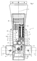
- the actuating device has a carrier housing 4, which is used in the rear area 1.
- the dimensionally stable carrier housing 4 supports the rear area 1 radially from the longitudinal axis F of the floor and thereby increases Radial pressure forces are created, so that the Wall thickness of the rear area 1 where it from Support housing 4 is supported to be smaller than usual can. This increases the usable space inside the Rear area 1.
- the motors 5,6 are side by side (cf. Fig. 3,4). Their motor shafts run parallel to one another. Both motors 5,6 have the same structure and the same Way connected to the assigned pair of oars. in the For simplification, the following is just one engine and described its coupling to its rudder pair. For the same applies to other motors.
- the motor is brushless and houseless. His stator 7 is inserted directly into the carrier housing 4, for example glued. Its rotor 8 sits on the Motor shaft 9.
- the motor shaft 9 is at both ends by means of Carrier housing 4 roller bearings 10 used, for example angular contact ball bearings.
- roller bearings 10 used, for example angular contact ball bearings.
- the bearing there is a disk 11 in the rear-side roller bearing 10 intended.
- the outer ring 12 of the Rolling bearing 10 on.
- the Disc 11 a step 40 with regard to the rolling bearing 10 precisely defined game between inner ring 13 and Outer ring 12 on.
- the inner ring 13 of the roller bearing 10 on the disc 11 on which the outer ring 12 stands.
- the axial force acting on the roller bearing 10 limited so that the rolling bearing 10 does not destroy becomes.
- the inner ring 13 of the deformed elastically by the launch acceleration Bearing back from the disc 11 so that the inner ring 13th free is.
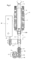
- the Motor shaft 9 has an internal thread 14 into which an axial Movable push spindle 15 secured against twisting engages with an external thread 16.
- an engagement nut 18 with one attached to the axis B of the one oar pair Driving lever 19 is coupled.
- the Adjustment position is by means of a counter screw 20 definable.
- the specified actuating device is small and comparatively easy. Few moving parts are sufficient for a smooth-running gear train.
- an arm 21 is attached to the an actuator 22 of a linear potentiometer 23 attacks.
- the linear potentiometer 23 is connected to one in the room 24 arranged control electronics connected.
- the Linear potentiometer 23 is in a recess 25 (cf. 3) the carrier housing 4 is arranged.
- About the Linear potentiometer 23 becomes the actual position of the control electronics of the respective oar pair reported.
- Linear potentiometers can also take other measures Detection of the actual position of the rudder may be provided.
Landscapes
- Physics & Mathematics (AREA)
- Fluid Mechanics (AREA)
- Engineering & Computer Science (AREA)
- General Engineering & Computer Science (AREA)
- Connection Of Motors, Electrical Generators, Mechanical Devices, And The Like (AREA)
Abstract
Description
Claims (10)
- Stelleinrichtung für Ruder eines Flugkörpers, wobei die Ruder von Stellmotoren über Schubspindeln verstellbar sind und die Stellmotoren in einem im Flugkörper angeordneten Trägergehäuse vorgesehen sind,
dadurch gekennzeichnet,
daß die Statoren(7) der Stellmotoren(5,6) unmittelbar im Trägergehäuse(4) angeordnet sind und daß die Schubspindel (15) in ein Innengewinde(14) der Motorwelle(9) eingreift. - Stelleinrichtung nach Anspruch 1,
dadurch gekennzeichnet,
daß das Innengewinde(14), in das die Schubspindel(15) eingreift, innerhalb eines die Motorwelle(9) lagernden Wälzlagers(10) liegt. - Stelleinrichtung nach Anspruch 1 oder 2,
dadurch gekennzeichnet,
daß ein die Motorwelle(9) lagerndes Wälzlager(10) einen Innenring(13) und einen Außenring(12) aufweist und daß der Innenring(13) und der Außenring(12) bei einer Abschußbeschleunigung des Flugkörpers sich im Trägergehäuse(4) abstützt. - Stelleinrichtung nach Anspruch 3,
dadurch gekennzeichnet,
daß eine Scheibe(11) im Trägergehäuse(4) angeordnet ist, an dem sich der Außenring(12) und bei einer Abschußbeschleunigung auch der Innenring(13) abstützt. - Stelleinrichtung nach einem der vorhergehenden Ansprüche,
dadurch gekennzeichnet,
daß das Wälzlager(10) ein Schrägkugellager ist. - Stelleinrichtung nach einem der vorhergehenden Ansprüche,
dadurch gekennzeichnet,
daß die Motorwellen(9) im Trägergehäuse(4) parallel zueinander und nebeneinander liegen. - Stelleinrichtung nach einem der vorhergehenden Ansprüche,
dadurch gekennzeichnet,
daß die Stellmotoren bürstenlose Motoren sind. - Stelleinrichtung nach einem der vorhergehenden Ansprüche,
dadurch gekennzeichnet,
daß das Trägergehäuse(4) den Heckbereich(1) des Flugkörpers gegen radiale Kräfte abstützt. - Stelleinrichtung nach einem der vorhergehenden Ansprüche,
dadurch gekennzeichnet,
daß die Lage der Ruder bezogen auf die Schubspindel(15) justierbar ist. - Stelleinrichtung nach einem der vorhergehenden Ansprüche,
dadurch gekennzeichnet,
daß ein Potentiometer(23) zur Rückmeldung der Ruderlage an eine Steuerelektronik vorgesehen ist und daß ein Stellglied(22) des Potentiometers(23) mit der Schubspindel(15) verbunden ist.
Applications Claiming Priority (2)
| Application Number | Priority Date | Filing Date | Title |
|---|---|---|---|
| DE19922693A DE19922693A1 (de) | 1999-05-18 | 1999-05-18 | Stelleinrichtung für Ruder eines Flugkörpers |
| DE19922693 | 1999-05-18 |
Publications (3)
| Publication Number | Publication Date |
|---|---|
| EP1054231A2 true EP1054231A2 (de) | 2000-11-22 |
| EP1054231A3 EP1054231A3 (de) | 2002-06-12 |
| EP1054231B1 EP1054231B1 (de) | 2005-11-30 |
Family
ID=7908347
Family Applications (1)
| Application Number | Title | Priority Date | Filing Date |
|---|---|---|---|
| EP00110018A Expired - Lifetime EP1054231B1 (de) | 1999-05-18 | 2000-05-12 | Stelleinrichtung für Ruder eines Flugkörpers |
Country Status (3)
| Country | Link |
|---|---|
| US (1) | US6299101B1 (de) |
| EP (1) | EP1054231B1 (de) |
| DE (2) | DE19922693A1 (de) |
Cited By (1)
| Publication number | Priority date | Publication date | Assignee | Title |
|---|---|---|---|---|
| WO2010005350A1 (en) * | 2008-07-07 | 2010-01-14 | Saab Ab | Rudder machinery |
Families Citing this family (7)
| Publication number | Priority date | Publication date | Assignee | Title |
|---|---|---|---|---|
| US6446906B1 (en) * | 2000-04-06 | 2002-09-10 | Versatron, Inc. | Fin and cover release system |
| DE102005038856A1 (de) | 2005-08-17 | 2007-02-22 | Airbus Deutschland Gmbh | Kontinuierlicher Rumpfanschluss |
| US8148670B2 (en) * | 2008-08-26 | 2012-04-03 | Woodward Hrt, Inc. | Rotary actuator ball-detent locking mechanism |
| US8324544B2 (en) | 2010-06-02 | 2012-12-04 | Woodward Hrt, Inc. | Multi-stage fin deployment assembly |
| US8624172B2 (en) * | 2010-10-13 | 2014-01-07 | Woodward Hrt, Inc. | Shift lock assembly |
| US9453531B2 (en) | 2013-08-26 | 2016-09-27 | Roller Bearing Company Of America, Inc. | Integrated bearing assemblies for guided attack rockets |
| US9605692B2 (en) | 2014-10-01 | 2017-03-28 | Woodward, Inc. | Locking rotary actuator |
Citations (3)
| Publication number | Priority date | Publication date | Assignee | Title |
|---|---|---|---|---|
| DE3441534A1 (de) | 1984-11-14 | 1986-05-15 | Diehl GmbH & Co, 8500 Nürnberg | Lageranordnung fuer das ruderblatt eines flugkoerpers |
| DE3441533C2 (de) | 1984-11-14 | 1989-07-20 | Diehl Gmbh & Co, 8500 Nuernberg, De | |
| DE4335785A1 (de) | 1993-10-20 | 1995-04-27 | Diehl Gmbh & Co | Ruderstelleinrichtung |
Family Cites Families (11)
| Publication number | Priority date | Publication date | Assignee | Title |
|---|---|---|---|---|
| US3154015A (en) * | 1962-09-19 | 1964-10-27 | Martin Marietta Corp | Missile flight control system |
| US4037806A (en) * | 1964-09-16 | 1977-07-26 | General Dynamics Corporation | Control system for rolling missile with target seeker head |
| US5393011A (en) * | 1965-12-03 | 1995-02-28 | Shorts Missile Systems Limited | Control systems for moving bodies |
| US4438893A (en) * | 1973-08-10 | 1984-03-27 | Sanders Associates, Inc. | Prime power source and control for a guided projectile |
| DE3613539C1 (de) * | 1986-04-22 | 1997-05-28 | Dornier Gmbh | Stelleinrichtung für aerodynamisch wirkende Flächen |
| DE3702733A1 (de) * | 1987-01-30 | 1988-08-11 | Diehl Gmbh & Co | Ruderstelleinrichtung |
| DE4135557C2 (de) * | 1991-10-29 | 1999-05-06 | Diehl Stiftung & Co | Ruderstelleinrichtung |
| US5528092A (en) * | 1992-06-23 | 1996-06-18 | Nippon Corporation | Spindle motor |
| DE4325218C2 (de) * | 1993-07-28 | 1998-10-22 | Diehl Stiftung & Co | Artillerie-Rakete und Verfahren zur Leistungssteigerung einer Artillerie-Rakete |
| US5593109A (en) * | 1995-01-10 | 1997-01-14 | Lucas Western, Inc. | Actuator system and method |
| US6073880A (en) * | 1998-05-18 | 2000-06-13 | Versatron, Inc. | Integrated missile fin deployment system |
-
1999
- 1999-05-18 DE DE19922693A patent/DE19922693A1/de not_active Withdrawn
-
2000
- 2000-04-04 US US09/542,326 patent/US6299101B1/en not_active Expired - Lifetime
- 2000-05-12 DE DE50011724T patent/DE50011724D1/de not_active Expired - Lifetime
- 2000-05-12 EP EP00110018A patent/EP1054231B1/de not_active Expired - Lifetime
Patent Citations (3)
| Publication number | Priority date | Publication date | Assignee | Title |
|---|---|---|---|---|
| DE3441534A1 (de) | 1984-11-14 | 1986-05-15 | Diehl GmbH & Co, 8500 Nürnberg | Lageranordnung fuer das ruderblatt eines flugkoerpers |
| DE3441533C2 (de) | 1984-11-14 | 1989-07-20 | Diehl Gmbh & Co, 8500 Nuernberg, De | |
| DE4335785A1 (de) | 1993-10-20 | 1995-04-27 | Diehl Gmbh & Co | Ruderstelleinrichtung |
Cited By (1)
| Publication number | Priority date | Publication date | Assignee | Title |
|---|---|---|---|---|
| WO2010005350A1 (en) * | 2008-07-07 | 2010-01-14 | Saab Ab | Rudder machinery |
Also Published As
| Publication number | Publication date |
|---|---|
| EP1054231B1 (de) | 2005-11-30 |
| EP1054231A3 (de) | 2002-06-12 |
| US6299101B1 (en) | 2001-10-09 |
| DE50011724D1 (de) | 2006-01-05 |
| DE19922693A1 (de) | 2000-11-23 |
Similar Documents
| Publication | Publication Date | Title |
|---|---|---|
| DE2622235C2 (de) | ||
| EP0743470B1 (de) | Bremsaktor für elektrisch betätigbare Fahrzeugbremse | |
| DE2157514C3 (de) | Wellenlagerung für ein Gasturbinenstrahltriebwerk | |
| DE112010005656B4 (de) | Elektromechanische Antriebseinrichtung der aerodynamischen Fläche des Flugzeuges | |
| EP1539558B1 (de) | Spielfreies lenkgetriebe | |
| DE4020897C2 (de) | Einrichtung zum Entriegeln und Ausschwenken der Ruderblätter eines Projektiles | |
| DE19640540C1 (de) | Ruderstellsystem für einen Lenkflugkörper | |
| DE10237644A1 (de) | Federträger mit einem höhenverstellbaren Federteller | |
| EP1054231A2 (de) | Stelleinrichtung für Ruder eines Flugkörpers | |
| DE69819826T2 (de) | Servosteuersystem | |
| DE2544272B2 (de) | Triebwerksaufhängung an Luftfahrzeugen | |
| EP0276867B1 (de) | Ruderstelleinrichtung | |
| DE102012212140B4 (de) | Bremsvorrichtung für eine direkt elektromechanisch aktuierte Planetengetriebeanordnung eines Sitzverstellmechanismus und Verfahren zum Betrieb einer Bremsvorrichtung | |
| DE3441534A1 (de) | Lageranordnung fuer das ruderblatt eines flugkoerpers | |
| DE102020203617A1 (de) | Kippsegmentlager und Verfahren zum Betreiben | |
| DE60220476T2 (de) | Anordnung einer Ausgangswelle für das Steuersystem einer Rakete | |
| DE4335785A1 (de) | Ruderstelleinrichtung | |
| EP0814315B1 (de) | Rakete | |
| DE102023120475B4 (de) | Antriebsvorrichtung für einen Roboter sowie Roboter mit einer solchen Antriebsvorrichtung | |
| DE2613225A1 (de) | Verstelleinrichtung fuer schiffspropeller, propellerpumpen und propellerturbinen | |
| DE4201257C2 (de) | Regelbare Flügelzellenpumpe mit Druckstück | |
| EP1108972A2 (de) | Vorrichtung zur Ruderanbindung für Lenkflugkörper | |
| DE102020114804B4 (de) | Lenksystem für einen Außenbordmotor | |
| EP3086078A1 (de) | Flugkörperrudersystem | |
| DE102010018210A1 (de) | Vorrichtung zur Verstellung der Drehwinkellage einer Welle |
Legal Events
| Date | Code | Title | Description |
|---|---|---|---|
| PUAI | Public reference made under article 153(3) epc to a published international application that has entered the european phase |
Free format text: ORIGINAL CODE: 0009012 |
|
| AK | Designated contracting states |
Kind code of ref document: A2 Designated state(s): AT BE CH CY DE DK ES FI FR GB GR IE IT LI LU MC NL PT SE |
|
| AX | Request for extension of the european patent |
Free format text: AL;LT;LV;MK;RO;SI |
|
| PUAL | Search report despatched |
Free format text: ORIGINAL CODE: 0009013 |
|
| AK | Designated contracting states |
Kind code of ref document: A3 Designated state(s): AT BE CH CY DE DK ES FI FR GB GR IE IT LI LU MC NL PT SE |
|
| AX | Request for extension of the european patent |
Free format text: AL;LT;LV;MK;RO;SI |
|
| 17P | Request for examination filed |
Effective date: 20020515 |
|
| AKX | Designation fees paid |
Designated state(s): DE FR GB IT |
|
| RAP1 | Party data changed (applicant data changed or rights of an application transferred) |
Owner name: DIEHL BGT DEFENCE GMBH & CO.KG |
|
| GRAP | Despatch of communication of intention to grant a patent |
Free format text: ORIGINAL CODE: EPIDOSNIGR1 |
|
| GRAS | Grant fee paid |
Free format text: ORIGINAL CODE: EPIDOSNIGR3 |
|
| GRAA | (expected) grant |
Free format text: ORIGINAL CODE: 0009210 |
|
| AK | Designated contracting states |
Kind code of ref document: B1 Designated state(s): DE FR GB IT |
|
| REG | Reference to a national code |
Ref country code: GB Ref legal event code: FG4D Free format text: NOT ENGLISH |
|
| REF | Corresponds to: |
Ref document number: 50011724 Country of ref document: DE Date of ref document: 20060105 Kind code of ref document: P |
|
| GBT | Gb: translation of ep patent filed (gb section 77(6)(a)/1977) |
Effective date: 20060202 |
|
| ET | Fr: translation filed | ||
| PLBE | No opposition filed within time limit |
Free format text: ORIGINAL CODE: 0009261 |
|
| STAA | Information on the status of an ep patent application or granted ep patent |
Free format text: STATUS: NO OPPOSITION FILED WITHIN TIME LIMIT |
|
| 26N | No opposition filed |
Effective date: 20060831 |
|
| REG | Reference to a national code |
Ref country code: FR Ref legal event code: PLFP Year of fee payment: 16 |
|
| PGFP | Annual fee paid to national office [announced via postgrant information from national office to epo] |
Ref country code: GB Payment date: 20150521 Year of fee payment: 16 |
|
| PGFP | Annual fee paid to national office [announced via postgrant information from national office to epo] |
Ref country code: IT Payment date: 20150514 Year of fee payment: 16 Ref country code: FR Payment date: 20150521 Year of fee payment: 16 |
|
| PGFP | Annual fee paid to national office [announced via postgrant information from national office to epo] |
Ref country code: DE Payment date: 20150721 Year of fee payment: 16 |
|
| REG | Reference to a national code |
Ref country code: DE Ref legal event code: R119 Ref document number: 50011724 Country of ref document: DE |
|
| GBPC | Gb: european patent ceased through non-payment of renewal fee |
Effective date: 20160512 |
|
| PG25 | Lapsed in a contracting state [announced via postgrant information from national office to epo] |
Ref country code: IT Free format text: LAPSE BECAUSE OF NON-PAYMENT OF DUE FEES Effective date: 20160512 |
|
| REG | Reference to a national code |
Ref country code: FR Ref legal event code: ST Effective date: 20170131 |
|
| PG25 | Lapsed in a contracting state [announced via postgrant information from national office to epo] |
Ref country code: FR Free format text: LAPSE BECAUSE OF NON-PAYMENT OF DUE FEES Effective date: 20160531 Ref country code: DE Free format text: LAPSE BECAUSE OF NON-PAYMENT OF DUE FEES Effective date: 20161201 |
|
| PG25 | Lapsed in a contracting state [announced via postgrant information from national office to epo] |
Ref country code: GB Free format text: LAPSE BECAUSE OF NON-PAYMENT OF DUE FEES Effective date: 20160512 |