EP1053930B1 - Vehicle - Google Patents
Vehicle Download PDFInfo
- Publication number
- EP1053930B1 EP1053930B1 EP00201795A EP00201795A EP1053930B1 EP 1053930 B1 EP1053930 B1 EP 1053930B1 EP 00201795 A EP00201795 A EP 00201795A EP 00201795 A EP00201795 A EP 00201795A EP 1053930 B1 EP1053930 B1 EP 1053930B1
- Authority
- EP
- European Patent Office
- Prior art keywords
- chassis
- vehicle
- upper side
- loading floor
- flat
- Prior art date
- Legal status (The legal status is an assumption and is not a legal conclusion. Google has not performed a legal analysis and makes no representation as to the accuracy of the status listed.)
- Revoked
Links
Images
Classifications
-
- B—PERFORMING OPERATIONS; TRANSPORTING
- B60—VEHICLES IN GENERAL
- B60P—VEHICLES ADAPTED FOR LOAD TRANSPORTATION OR TO TRANSPORT, TO CARRY, OR TO COMPRISE SPECIAL LOADS OR OBJECTS
- B60P1/00—Vehicles predominantly for transporting loads and modified to facilitate loading, consolidating the load, or unloading
- B60P1/64—Vehicles predominantly for transporting loads and modified to facilitate loading, consolidating the load, or unloading the load supporting or containing element being readily removable
- B60P1/6418—Vehicles predominantly for transporting loads and modified to facilitate loading, consolidating the load, or unloading the load supporting or containing element being readily removable the load-transporting element being a container or similar
- B60P1/6481—Specially adapted for carrying different numbers of container or containers of different sizes
-
- B—PERFORMING OPERATIONS; TRANSPORTING
- B62—LAND VEHICLES FOR TRAVELLING OTHERWISE THAN ON RAILS
- B62D—MOTOR VEHICLES; TRAILERS
- B62D25/00—Superstructure or monocoque structure sub-units; Parts or details thereof not otherwise provided for
- B62D25/20—Floors or bottom sub-units
- B62D25/2054—Load carrying floors for commercial vehicles
-
- B—PERFORMING OPERATIONS; TRANSPORTING
- B62—LAND VEHICLES FOR TRAVELLING OTHERWISE THAN ON RAILS
- B62D—MOTOR VEHICLES; TRAILERS
- B62D53/00—Tractor-trailer combinations; Road trains
- B62D53/04—Tractor-trailer combinations; Road trains comprising a vehicle carrying an essential part of the other vehicle's load by having supporting means for the front or rear part of the other vehicle
- B62D53/06—Semi-trailers
Definitions
- the invention relates to a vehicle, comprising a chassis and an undercarriage connected thereto, wherein the chassis comprises at least one upward curved chassis beam and a loading floor connected thereto.
- a vehicle comprising a chassis and an undercarriage connected thereto, wherein the chassis comprises at least one upward curved chassis beam and a loading floor connected thereto.
- Such a vehicle is known, for instance in the form of a flat bed trailer marketed by applicant.
- Such a flat bed trailer is provided with a goose-neck for fixing to a tractor and a chassis which is connected thereto and consists of a central beam or girder, or of two parallel beams or girders on the outside, and which is provided with a multi-axle undercarriage on the side remote from the goose-neck.
- the girder or girders herein supports/support a loading floor on which the cargo can be placed.
- chassis beams In such vehicles a trend can be discerned of embodying the chassis beams increasingly lower. This offers advantages, since in many countries the maximum transport height of vehicles is limited by law. Lower chassis beams thus leave more space for a higher cargo. However, because the space within the chassis beams, which in practice is usually used for feed-through of all types of lines, is also limited by the lower embodiment of these beams, the wall thickness of the beams is also being reduced to an increasing extent, whereby the inner space thereof is thus retained. This is particular the case with vehicles which are adjustable in the length, and wherein in the retracted situation the lines lie in a loop in the chassis beams.
- chassis beams This lower height and smaller wall thickness of the chassis beams have the result that these latter must be embodied in higher-grade types of steel in order to still achieve the required strength. It is however not possible herein to also preserve the original rigidity. This therefore has the consequence that the chassis beams increasingly take a less rigid form, and will thus sag more under the influence of both their own weight and the weight of the cargo arranged on the vehicle.
- Chassis beams are at present therefore often given an upward curved or convex form in order to compensate the troublesome consequences of this greater sagging.
- the ground clearance which is per se limited, is of crucial importance and the upward curvature of the chassis beams is chosen such that these are as flat as possible in the loaded situation, and the ground clearance is thus constant along the whole length of the loading floor.
- the chassis beams will generally take a curved form such that they are as flat as possible in unloaded but extended situation. In this situation it is generally self-supporting cargo which is transported with such vehicles, which cargo will rest only on the coupling between the vehicle and the tractor and on the undercarriage. This therefore causes no sagging of the chassis beams.
- the known vehicles with convex chassis beams have the drawback that the loading floor defined by the girders is curved under all conditions. This is a particular problem in the case of low bed semi-trailers and flat trailers when containers are transported, since these latter will often not be sufficiently heavily loaded to cause the girders to sag to a completely flat position. Because containers have to be fastened to the loading floor by means of rotatable and slidable locking elements, so-called “twist-locks", which allow only a limited clearance, the convex form of the girders has the result that not all four "twist-locks" of the container can be fastened to the loading floor, whereby the container is thus not firmly secured during transport.
- the invention now has for its object to provide a vehicle of the above stated type, wherein this problem does not occur. According to the invention this is achieved by the features of claim 1. At least the loading floor is substantially flat on the upper side. Cargo which is flat on the underside can in this way be transported simply and in safe manner, while the adverse effects of the sagging of the chassis beam or beams nonetheless remain limited.
- the or each chassis beam is herein substantially flat on the upper side. In this manner the flat loading floor can be arranged thereon without further modifications.
- the or each chassis beam can be adjustable in the length and have at least two curved beam parts which are slidable relative to each other and at least one of which can be connected to the loading floor and have a substantially flat upper side.
- the beam parts are preferably telescopically slidable relative to each other, and at least the outer beam part has a substantially flat upper side.
- a flat and extensible loading floor can thus be obtained, while the majority of the beam parts can still take a curved form.
- the outer beam part can herein have an inner contour which corresponds at least partly with the curvature of the or each beam part slidable therein.
- This contour corresponding with the curvature of the other beam parts can be formed by a curved underside and at least one filling element protruding inwardly from the flat upper side, while a number of filling elements are preferably even arranged evenly distributed in longitudinal direction of the outer beam part.
- the radius of curvature of the chassis beam is preferably at least an order greater than the length thereof, and can lie between 10 and 100 times, more particularly 30 to 60 times the length of this chassis beam.
- a vehicle 1, in the example shown a low bed semi-trailer (fig. 1), comprises a chassis 2 which is provided on the front side with a goose-neck 3, which via a rotatable coupling plate 4 can be connected to a tractive vehicle (not shown here).
- Goose-neck 3 is herein formed by a flat part 16 and, pivotally connected thereto, an upright end part 17 of a chassis beam 9 to be further discussed hereinbelow.
- Chassis 2 is provided on the rear side with an undercarriage 5, which in the shown embodiment has six axles 6 with wheels 7, wherein the five rearmost wheel sets take a steerable form.
- At the front side of vehicle 1 in the vicinity of goose-neck 3 are further arranged two extending supports 8 on which vehicle 1 rests when it is not resting on a tractor.
- Chassis 2 is formed by chassis beam 9 and a loading floor 10 supported thereby. Loading floor 10 is supported by cross members 11 mounted on chassis beam 9. Chassis beam 9 and therewith chassis 2 is adjustable in the length in the shown embodiment. For this purpose chassis beam 9 is assembled from three beam parts 12, 13 and 14 telescopically slidable into each other (fig. 2).
- chassis beam 9 In order to limit the sagging of chassis beam 9 in the loaded (or the unloaded but extended) situation, it is further formed such that in unloaded and/or retracted situation it is slightly convex (shown in broken lines in fig. 6). This is particularly important in relatively low vehicles, such as flat bed trailers and low bed semi-trailers, where there is not enough space to give the chassis beam so high a form that the sagging thereof would also be acceptable in the case of a completely straight beam.
- Beam parts 12, 13 and 14 are thus slidable relative to each other along a curved path. At least the inner beam parts 12 and 13, i.e. those beam parts which have the smallest cross-section in the embodiment shown, themselves also take a curved form herein.
- the outer beam part 14 however does not take a curved form or not a completely curved form, and has in any case a substantially flat upper side 15. In this manner is ensured that the loading floor 10 mounted on chassis beam 9 can also be substantially flat, which is important for instance in the transport of containers which, using four so-called “twist-locks" arranged in loading floor 10, must be secured to loading floor 10 at their corner points or "corner castings". If the upper side of chassis beam 9, and therewith loading floor 10, were to have an upward curved form, not all "twist-locks" would be able to reach the corner points of the container. In addition, the flat upper side of the outer beam part 14 has the advantage that chassis beam 9 can hereby be manufactured lying upside down in a flat mould.
- the outer beam part 14 has an inner contour which corresponds with the curvature of the beam parts 12 and 13 slidable therein.
- this beam part 14 is provided in the embodiment shown with a curved bottom 18 and a number of filling elements 19, 20 protruding from upper side 15, which is also flat on the inner side.
- the foremost filling element 19 is herein intended to function as supporting surface S in determined load conditions and to transmit loads from outer beam part 14 to the upper side of the subsequent beam part 13. Such a load condition could occur in the embodiment shown if chassis beam 9 is retracted (fig. 5a). In the shown situation the underside of beam part 13 would in addition be loaded at the rear by the bottom 18 of outer beam part 13, which forms a second supporting surface S.
- the rearmost filling element 20 on the other hand functions to transfer loads between beam parts 13 and 14 in other load situations, one of which is shown here in the extended situation of chassis beam 9 (fig. 5b).
- More filling elements could of course also be present instead of these two filling elements 19 and 20 or use could be made of a continuous filling element with the desired contour.
- the outer beam part 14 as a whole to take a curved form, and be provided with an upper girder which is fixed thereon via one or more web plates and on which the loading floor can be arranged.
- the loading floor resting directly on the curved beam only at the highest point, and filling elements or supports being arranged between the other, lower-lying parts of the beam and the loading floor.
- chassis 2 filling pieces 21, 22 can otherwise be placed on the front side thereof on the slightly protruding ends of the inner beam parts 12, 13 which, as a result of their curvature, are in any case situated somewhat lower than the upper surface 15 of beam part 14 and thus loading floor 10. In this manner a flat loading floor is obtained along the whole length of vehicle 1.
- the vehicle could thus also have a fixed length, wherein a single, continuous chassis beam could thus be applied.
- more or fewer than the three beam parts shown could be applied, while beam parts with a cross-sectional shape other than that shown could also be envisaged. It is even possible in this case to envisage beam parts with an open profile shape, which are not slidable into but alongside each other.
- application of the invention is not limited to low bed semi-trailers, but other vehicles such as flat trailers or flat bed trailers can also be embodied in this manner.
Abstract
Description
- The invention relates to a vehicle, comprising a chassis and an undercarriage connected thereto, wherein the chassis comprises at least one upward curved chassis beam and a loading floor connected thereto. Such a vehicle is known, for instance in the form of a flat bed trailer marketed by applicant.
- Such a flat bed trailer is provided with a goose-neck for fixing to a tractor and a chassis which is connected thereto and consists of a central beam or girder, or of two parallel beams or girders on the outside, and which is provided with a multi-axle undercarriage on the side remote from the goose-neck. The girder or girders herein supports/support a loading floor on which the cargo can be placed.
- In such vehicles a trend can be discerned of embodying the chassis beams increasingly lower. This offers advantages, since in many countries the maximum transport height of vehicles is limited by law. Lower chassis beams thus leave more space for a higher cargo. However, because the space within the chassis beams, which in practice is usually used for feed-through of all types of lines, is also limited by the lower embodiment of these beams, the wall thickness of the beams is also being reduced to an increasing extent, whereby the inner space thereof is thus retained. This is particular the case with vehicles which are adjustable in the length, and wherein in the retracted situation the lines lie in a loop in the chassis beams.
- This lower height and smaller wall thickness of the chassis beams have the result that these latter must be embodied in higher-grade types of steel in order to still achieve the required strength. It is however not possible herein to also preserve the original rigidity. This therefore has the consequence that the chassis beams increasingly take a less rigid form, and will thus sag more under the influence of both their own weight and the weight of the cargo arranged on the vehicle.
- Chassis beams are at present therefore often given an upward curved or convex form in order to compensate the troublesome consequences of this greater sagging. In the case of a flat bed trailer the ground clearance, which is per se limited, is of crucial importance and the upward curvature of the chassis beams is chosen such that these are as flat as possible in the loaded situation, and the ground clearance is thus constant along the whole length of the loading floor. In the case of an extensible low bed semi-trailer or flat trailer the chassis beams will generally take a curved form such that they are as flat as possible in unloaded but extended situation. In this situation it is generally self-supporting cargo which is transported with such vehicles, which cargo will rest only on the coupling between the vehicle and the tractor and on the undercarriage. This therefore causes no sagging of the chassis beams.
- The known vehicles with convex chassis beams have the drawback that the loading floor defined by the girders is curved under all conditions. This is a particular problem in the case of low bed semi-trailers and flat trailers when containers are transported, since these latter will often not be sufficiently heavily loaded to cause the girders to sag to a completely flat position. Because containers have to be fastened to the loading floor by means of rotatable and slidable locking elements, so-called "twist-locks", which allow only a limited clearance, the convex form of the girders has the result that not all four "twist-locks" of the container can be fastened to the loading floor, whereby the container is thus not firmly secured during transport.
- The invention now has for its object to provide a vehicle of the above stated type, wherein this problem does not occur. According to the invention this is achieved by the features of
claim 1. At least the loading floor is substantially flat on the upper side. Cargo which is flat on the underside can in this way be transported simply and in safe manner, while the adverse effects of the sagging of the chassis beam or beams nonetheless remain limited. - Moreover, the or each chassis beam is herein substantially flat on the upper side. In this manner the flat loading floor can be arranged thereon without further modifications.
- In order to enable an increase in the capacity of the vehicle, the or each chassis beam can be adjustable in the length and have at least two curved beam parts which are slidable relative to each other and at least one of which can be connected to the loading floor and have a substantially flat upper side.
- The beam parts are preferably telescopically slidable relative to each other, and at least the outer beam part has a substantially flat upper side. A flat and extensible loading floor can thus be obtained, while the majority of the beam parts can still take a curved form. The outer beam part can herein have an inner contour which corresponds at least partly with the curvature of the or each beam part slidable therein. This contour corresponding with the curvature of the other beam parts can be formed by a curved underside and at least one filling element protruding inwardly from the flat upper side, while a number of filling elements are preferably even arranged evenly distributed in longitudinal direction of the outer beam part.
- The radius of curvature of the chassis beam is preferably at least an order greater than the length thereof, and can lie between 10 and 100 times, more particularly 30 to 60 times the length of this chassis beam.
- The invention will now be elucidated on the basis of an embodiment, wherein reference is made to the annexed drawing, in which:
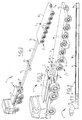
- figures 1a and 1b are respectively a top view and a side view of a pulled vehicle with adjustable length according to the invention in retracted situation,
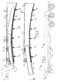
- figure 2 is a side view on smaller scale of the vehicle in fully extended situation,
- figure 3 is a longitudinal section through a chassis beam of the vehicle of figures 1 and 2 in the retracted situation,
- figure 4 shows a front view of the chassis beam of figure 3,
- figures 5a and 5b show schematically and on highly exaggerated scale in vertical height the length-adjustable chassis beam in the retracted and extended situation, and
- figure 6 shows schematically the sagging of the chassis beam in loaded situation.
- A
vehicle 1, in the example shown a low bed semi-trailer (fig. 1), comprises achassis 2 which is provided on the front side with a goose-neck 3, which via arotatable coupling plate 4 can be connected to a tractive vehicle (not shown here). Goose-neck 3 is herein formed by a flat part 16 and, pivotally connected thereto, anupright end part 17 of achassis beam 9 to be further discussed hereinbelow.Chassis 2 is provided on the rear side with anundercarriage 5, which in the shown embodiment has sixaxles 6 with wheels 7, wherein the five rearmost wheel sets take a steerable form. At the front side ofvehicle 1 in the vicinity of goose-neck 3 are further arranged two extending supports 8 on whichvehicle 1 rests when it is not resting on a tractor. -
Chassis 2 is formed bychassis beam 9 and aloading floor 10 supported thereby. Loadingfloor 10 is supported by cross members 11 mounted onchassis beam 9.Chassis beam 9 and therewithchassis 2 is adjustable in the length in the shown embodiment. For thispurpose chassis beam 9 is assembled from threebeam parts - In order to limit the sagging of
chassis beam 9 in the loaded (or the unloaded but extended) situation, it is further formed such that in unloaded and/or retracted situation it is slightly convex (shown in broken lines in fig. 6). This is particularly important in relatively low vehicles, such as flat bed trailers and low bed semi-trailers, where there is not enough space to give the chassis beam so high a form that the sagging thereof would also be acceptable in the case of a completely straight beam.Beam parts inner beam parts - The
outer beam part 14 however does not take a curved form or not a completely curved form, and has in any case a substantially flatupper side 15. In this manner is ensured that theloading floor 10 mounted onchassis beam 9 can also be substantially flat, which is important for instance in the transport of containers which, using four so-called "twist-locks" arranged inloading floor 10, must be secured to loadingfloor 10 at their corner points or "corner castings". If the upper side ofchassis beam 9, and therewithloading floor 10, were to have an upward curved form, not all "twist-locks" would be able to reach the corner points of the container. In addition, the flat upper side of theouter beam part 14 has the advantage thatchassis beam 9 can hereby be manufactured lying upside down in a flat mould. - The
outer beam part 14 has an inner contour which corresponds with the curvature of thebeam parts beam part 14 is provided in the embodiment shown with acurved bottom 18 and a number offilling elements upper side 15, which is also flat on the inner side. Theforemost filling element 19 is herein intended to function as supporting surface S in determined load conditions and to transmit loads fromouter beam part 14 to the upper side of thesubsequent beam part 13. Such a load condition could occur in the embodiment shown ifchassis beam 9 is retracted (fig. 5a). In the shown situation the underside ofbeam part 13 would in addition be loaded at the rear by thebottom 18 ofouter beam part 13, which forms a second supporting surface S. (In these figures arrows Fw herein show the supporting force exerted by wheels 7, Ft is the bearing force of the tractor and arrows Fl indicate the load by the cargo). Therearmost filling element 20 on the other hand functions to transfer loads betweenbeam parts - More filling elements could of course also be present instead of these two
filling elements outer beam part 14 as a whole to take a curved form, and be provided with an upper girder which is fixed thereon via one or more web plates and on which the loading floor can be arranged. On the other hand it is also possible to envisage the loading floor resting directly on the curved beam only at the highest point, and filling elements or supports being arranged between the other, lower-lying parts of the beam and the loading floor. - In the retracted situation of
chassis 2filling pieces inner beam parts upper surface 15 ofbeam part 14 and thus loadingfloor 10. In this manner a flat loading floor is obtained along the whole length ofvehicle 1. - Although the invention is described above with reference to an embodiment, it is not limited thereto. The vehicle could thus also have a fixed length, wherein a single, continuous chassis beam could thus be applied. In the case of an extensible vehicle, more or fewer than the three beam parts shown could be applied, while beam parts with a cross-sectional shape other than that shown could also be envisaged. It is even possible in this case to envisage beam parts with an open profile shape, which are not slidable into but alongside each other. Finally, application of the invention is not limited to low bed semi-trailers, but other vehicles such as flat trailers or flat bed trailers can also be embodied in this manner.
- The scope of the invention is therefore limited solely by the now following claims.
Claims (9)
- Vehicle (1) comprising a chassis (2) and an undercarriage (5) connected thereto, wherein the chassis (2) comprises at least one upward curved chassis beam (9) and a loading floor (10) connected thereto, characterized in that at least the loading floor (10) is substantially flat on the upper side, and in that the or each chassis beam (9) is substantially flat on the upper side.
- Vehicle (1) as claimed in claim 1, characterized in that the or each chassis beam (9) is adjustable in the length and has at least two curved beam parts (12, 13, 14) which are slidable relative to each other and at least one (14) of which is connected to the loading floor (10) and has a substantially flat upper side (15).
- Vehicle (1) as claimed in claim 2, characterized in that the beam parts (12, 13, 14) are telescopically slidable relative to each other, and at least the outer beam part (14) has a substantially flat upper side (15).
- Vehicle (1) as claimed in claim 3, characterized in that the outer beam part (14) has an inner contour which corresponds at least partly with the curvature of the or each beam part (12, 13) slidable therein.
- Vehicle (1) as claimed in claim 4, characterized in that the outer beam part (14) has a curved underside (18) and at least one filling element (19, 20) protruding inwardly from the flat upper side (15).
- Vehicle (1) as claimed in claim 5, characterized by a number of filling elements (19, 20) arranged evenly distributed in longitudinal direction of the outer beam part (14).
- Vehicle (1) as claimed in any of the foregoing claims, characterized in that the radius of curvature of the chassis beam (9) is at least an order greater than the length thereof.
- Vehicle (1) as claimed in claim 7, characterized in that the radius of curvature of the chassis beam (9) amounts to between 10 and 100 times, more particularly 30 to 60 times the length thereof.
- Vehicle (1) as claimed in any of the foregoing claims, characterized by means (4) for coupling the vehicle (1) to a tractor.
Applications Claiming Priority (2)
| Application Number | Priority Date | Filing Date | Title |
|---|---|---|---|
| NL1012122A NL1012122C2 (en) | 1999-05-21 | 1999-05-21 | Vehicle. |
| NL1012122 | 1999-05-21 |
Publications (2)
| Publication Number | Publication Date |
|---|---|
| EP1053930A1 EP1053930A1 (en) | 2000-11-22 |
| EP1053930B1 true EP1053930B1 (en) | 2006-08-02 |
Family
ID=19769229
Family Applications (1)
| Application Number | Title | Priority Date | Filing Date |
|---|---|---|---|
| EP00201795A Revoked EP1053930B1 (en) | 1999-05-21 | 2000-05-22 | Vehicle |
Country Status (5)
| Country | Link |
|---|---|
| EP (1) | EP1053930B1 (en) |
| AT (1) | ATE334866T1 (en) |
| DE (1) | DE60029678T2 (en) |
| ES (1) | ES2265321T3 (en) |
| NL (1) | NL1012122C2 (en) |
Families Citing this family (3)
| Publication number | Priority date | Publication date | Assignee | Title |
|---|---|---|---|---|
| DK2373520T3 (en) | 2008-12-09 | 2014-05-05 | Vestas Wind Sys As | TRANSPORT SYSTEM |
| CN102602413B (en) * | 2012-03-28 | 2014-04-16 | 南车二七车辆有限公司 | Variable underframe for oversize commodity car |
| DE102016112310A1 (en) * | 2016-07-05 | 2017-08-17 | Ostfalia Hochschule Für Angewandte Wissenschaften - Hochschule Braunschweig/Wolfenbüttel | Loading floor for a vehicle and vehicle with the loading floor |
Family Cites Families (4)
| Publication number | Priority date | Publication date | Assignee | Title |
|---|---|---|---|---|
| NL171970B (en) * | 1951-09-26 | Interstate Ocean Transport | SEAWORTHY, STYLY CONNECTIBLE PUSH COMBINATION. | |
| FR2370618A1 (en) * | 1976-11-10 | 1978-06-09 | Gatserelia Michel | Chassis for vehicle tower trailer - has beam height reduced by cutting and bending web to secure to remainder of beam by welding |
| FR2486011B1 (en) * | 1980-07-04 | 1988-06-17 | Sainte Catherine Atel | VAN BODY WITH INTEGRATED CHASSIS |
| GB8904633D0 (en) * | 1989-03-01 | 1989-04-12 | Stead Brian | Heavy goods vehicle trailers |
-
1999
- 1999-05-21 NL NL1012122A patent/NL1012122C2/en not_active IP Right Cessation
-
2000
- 2000-05-22 DE DE60029678T patent/DE60029678T2/en not_active Expired - Lifetime
- 2000-05-22 EP EP00201795A patent/EP1053930B1/en not_active Revoked
- 2000-05-22 AT AT00201795T patent/ATE334866T1/en not_active IP Right Cessation
- 2000-05-22 ES ES00201795T patent/ES2265321T3/en not_active Expired - Lifetime
Also Published As
| Publication number | Publication date |
|---|---|
| NL1012122C2 (en) | 2000-11-23 |
| DE60029678D1 (en) | 2006-09-14 |
| EP1053930A1 (en) | 2000-11-22 |
| DE60029678T2 (en) | 2007-10-25 |
| ATE334866T1 (en) | 2006-08-15 |
| ES2265321T3 (en) | 2007-02-16 |
Similar Documents
| Publication | Publication Date | Title |
|---|---|---|
| CA2075874C (en) | Railway spine car | |
| EP2610106B1 (en) | Container trailer | |
| EP3468858B1 (en) | Adjustable semitrailer with steerable axle carrier | |
| US4666181A (en) | Inside loader, embodied as a semi-trailer for a tractor truck, for over-the-road transport frames, in particular for transporting flat glass | |
| US10683042B2 (en) | Transport trailer with a chassis and at least one floor platform | |
| US5407309A (en) | All purpose railway spine car | |
| US20060055141A1 (en) | Semi-trailer chassis and wheel suspension | |
| US5773768A (en) | Transport and on-board weighing device with a stabilizer thereof | |
| BG61869B1 (en) | Railway truck for shipment of semitrailers | |
| EP0219151B1 (en) | Cargo transporter, particularly of the trailer type having a front elevated loading floor | |
| EP1053930B1 (en) | Vehicle | |
| US9381846B2 (en) | Haul bodies and related apparatus | |
| CA2044127C (en) | Dumping semi-trailer | |
| US4500249A (en) | Self-adjusting boat trailer cradle | |
| EP1775203B1 (en) | Semitrailer | |
| JPS5930579B2 (en) | transport vehicle | |
| EP2873558B1 (en) | Semi-trailer for transporting goods | |
| US5393084A (en) | Swivel bunked double trailers for containers | |
| PL180361B1 (en) | Articulated car with a central beam | |
| EP0153023B1 (en) | Apparatus for supporting vehicles and the like | |
| RU2772762C1 (en) | Multi-turn fastener for transportation of automobile semi-trailers on flat wagons | |
| RU2772762C9 (en) | Multi-turn fastener for transportation of automobile semi-trailers on flat wagons | |
| EP1034105B1 (en) | Rail transport unit for transporting palletised or high volume loads | |
| GB2331970A (en) | Rail transport unit for transporting palletised or high volume loads | |
| JPH03500275A (en) | Vertically adjustable trailer |
Legal Events
| Date | Code | Title | Description |
|---|---|---|---|
| PUAI | Public reference made under article 153(3) epc to a published international application that has entered the european phase |
Free format text: ORIGINAL CODE: 0009012 |
|
| AK | Designated contracting states |
Kind code of ref document: A1 Designated state(s): AT BE CH CY DE DK ES FI FR GB GR IE IT LI LU MC NL PT SE |
|
| AX | Request for extension of the european patent |
Free format text: AL;LT;LV;MK;RO;SI |
|
| 17P | Request for examination filed |
Effective date: 20010202 |
|
| AKX | Designation fees paid |
Free format text: AT BE CH CY DE DK ES FI FR GB GR IE IT LI LU MC NL PT SE |
|
| 17Q | First examination report despatched |
Effective date: 20050628 |
|
| GRAP | Despatch of communication of intention to grant a patent |
Free format text: ORIGINAL CODE: EPIDOSNIGR1 |
|
| RTI1 | Title (correction) |
Free format text: VEHICLE |
|
| GRAS | Grant fee paid |
Free format text: ORIGINAL CODE: EPIDOSNIGR3 |
|
| GRAA | (expected) grant |
Free format text: ORIGINAL CODE: 0009210 |
|
| AK | Designated contracting states |
Kind code of ref document: B1 Designated state(s): AT BE CH CY DE DK ES FI FR GB GR IE IT LI LU MC NL PT SE |
|
| PG25 | Lapsed in a contracting state [announced via postgrant information from national office to epo] |
Ref country code: IT Free format text: LAPSE BECAUSE OF FAILURE TO SUBMIT A TRANSLATION OF THE DESCRIPTION OR TO PAY THE FEE WITHIN THE PRESCRIBED TIME-LIMIT;WARNING: LAPSES OF ITALIAN PATENTS WITH EFFECTIVE DATE BEFORE 2007 MAY HAVE OCCURRED AT ANY TIME BEFORE 2007. THE CORRECT EFFECTIVE DATE MAY BE DIFFERENT FROM THE ONE RECORDED. Effective date: 20060802 Ref country code: AT Free format text: LAPSE BECAUSE OF FAILURE TO SUBMIT A TRANSLATION OF THE DESCRIPTION OR TO PAY THE FEE WITHIN THE PRESCRIBED TIME-LIMIT Effective date: 20060802 Ref country code: LI Free format text: LAPSE BECAUSE OF FAILURE TO SUBMIT A TRANSLATION OF THE DESCRIPTION OR TO PAY THE FEE WITHIN THE PRESCRIBED TIME-LIMIT Effective date: 20060802 Ref country code: FI Free format text: LAPSE BECAUSE OF FAILURE TO SUBMIT A TRANSLATION OF THE DESCRIPTION OR TO PAY THE FEE WITHIN THE PRESCRIBED TIME-LIMIT Effective date: 20060802 Ref country code: CH Free format text: LAPSE BECAUSE OF FAILURE TO SUBMIT A TRANSLATION OF THE DESCRIPTION OR TO PAY THE FEE WITHIN THE PRESCRIBED TIME-LIMIT Effective date: 20060802 |
|
| REG | Reference to a national code |
Ref country code: GB Ref legal event code: FG4D |
|
| REG | Reference to a national code |
Ref country code: CH Ref legal event code: EP |
|
| REG | Reference to a national code |
Ref country code: IE Ref legal event code: FG4D |
|
| REF | Corresponds to: |
Ref document number: 60029678 Country of ref document: DE Date of ref document: 20060914 Kind code of ref document: P |
|
| PG25 | Lapsed in a contracting state [announced via postgrant information from national office to epo] |
Ref country code: DK Free format text: LAPSE BECAUSE OF FAILURE TO SUBMIT A TRANSLATION OF THE DESCRIPTION OR TO PAY THE FEE WITHIN THE PRESCRIBED TIME-LIMIT Effective date: 20061102 Ref country code: SE Free format text: LAPSE BECAUSE OF FAILURE TO SUBMIT A TRANSLATION OF THE DESCRIPTION OR TO PAY THE FEE WITHIN THE PRESCRIBED TIME-LIMIT Effective date: 20061102 |
|
| PG25 | Lapsed in a contracting state [announced via postgrant information from national office to epo] |
Ref country code: PT Free format text: LAPSE BECAUSE OF FAILURE TO SUBMIT A TRANSLATION OF THE DESCRIPTION OR TO PAY THE FEE WITHIN THE PRESCRIBED TIME-LIMIT Effective date: 20070102 |
|
| ET | Fr: translation filed | ||
| REG | Reference to a national code |
Ref country code: CH Ref legal event code: PL |
|
| REG | Reference to a national code |
Ref country code: ES Ref legal event code: FG2A Ref document number: 2265321 Country of ref document: ES Kind code of ref document: T3 |
|
| PLBI | Opposition filed |
Free format text: ORIGINAL CODE: 0009260 |
|
| 26 | Opposition filed |
Opponent name: DOLL FAHRZEUGBAU GMBH Effective date: 20070502 |
|
| PLAX | Notice of opposition and request to file observation + time limit sent |
Free format text: ORIGINAL CODE: EPIDOSNOBS2 |
|
| NLR1 | Nl: opposition has been filed with the epo |
Opponent name: DOLL FAHRZEUGBAU GMBH |
|
| PLAF | Information modified related to communication of a notice of opposition and request to file observations + time limit |
Free format text: ORIGINAL CODE: EPIDOSCOBS2 |
|
| PLAF | Information modified related to communication of a notice of opposition and request to file observations + time limit |
Free format text: ORIGINAL CODE: EPIDOSCOBS2 |
|
| PG25 | Lapsed in a contracting state [announced via postgrant information from national office to epo] |
Ref country code: MC Free format text: LAPSE BECAUSE OF NON-PAYMENT OF DUE FEES Effective date: 20070531 |
|
| PG25 | Lapsed in a contracting state [announced via postgrant information from national office to epo] |
Ref country code: GR Free format text: LAPSE BECAUSE OF FAILURE TO SUBMIT A TRANSLATION OF THE DESCRIPTION OR TO PAY THE FEE WITHIN THE PRESCRIBED TIME-LIMIT Effective date: 20061103 |
|
| PLBB | Reply of patent proprietor to notice(s) of opposition received |
Free format text: ORIGINAL CODE: EPIDOSNOBS3 |
|
| PG25 | Lapsed in a contracting state [announced via postgrant information from national office to epo] |
Ref country code: IE Free format text: LAPSE BECAUSE OF NON-PAYMENT OF DUE FEES Effective date: 20070522 |
|
| PLAY | Examination report in opposition despatched + time limit |
Free format text: ORIGINAL CODE: EPIDOSNORE2 |
|
| PG25 | Lapsed in a contracting state [announced via postgrant information from national office to epo] |
Ref country code: CY Free format text: LAPSE BECAUSE OF FAILURE TO SUBMIT A TRANSLATION OF THE DESCRIPTION OR TO PAY THE FEE WITHIN THE PRESCRIBED TIME-LIMIT Effective date: 20060802 |
|
| RAP2 | Party data changed (patent owner data changed or rights of a patent transferred) |
Owner name: NOOTEBOOM GROUP B.V. |
|
| NLT2 | Nl: modifications (of names), taken from the european patent patent bulletin |
Owner name: NOOTEBOOM GROUP B.V. Effective date: 20090930 |
|
| PLAH | Information related to despatch of examination report in opposition + time limit modified |
Free format text: ORIGINAL CODE: EPIDOSCORE2 |
|
| PLBC | Reply to examination report in opposition received |
Free format text: ORIGINAL CODE: EPIDOSNORE3 |
|
| REG | Reference to a national code |
Ref country code: NL Ref legal event code: SD Effective date: 20100218 |
|
| REG | Reference to a national code |
Ref country code: GB Ref legal event code: 732E Free format text: REGISTERED BETWEEN 20100401 AND 20100407 |
|
| PLAY | Examination report in opposition despatched + time limit |
Free format text: ORIGINAL CODE: EPIDOSNORE2 |
|
| PLAH | Information related to despatch of examination report in opposition + time limit modified |
Free format text: ORIGINAL CODE: EPIDOSCORE2 |
|
| PLBC | Reply to examination report in opposition received |
Free format text: ORIGINAL CODE: EPIDOSNORE3 |
|
| PGFP | Annual fee paid to national office [announced via postgrant information from national office to epo] |
Ref country code: DE Payment date: 20140530 Year of fee payment: 15 |
|
| RDAF | Communication despatched that patent is revoked |
Free format text: ORIGINAL CODE: EPIDOSNREV1 |
|
| PLAB | Opposition data, opponent's data or that of the opponent's representative modified |
Free format text: ORIGINAL CODE: 0009299OPPO |
|
| R26 | Opposition filed (corrected) |
Opponent name: DOLL FAHRZEUGBAU GMBH Effective date: 20070502 |
|
| APBM | Appeal reference recorded |
Free format text: ORIGINAL CODE: EPIDOSNREFNO |
|
| APBP | Date of receipt of notice of appeal recorded |
Free format text: ORIGINAL CODE: EPIDOSNNOA2O |
|
| APAH | Appeal reference modified |
Free format text: ORIGINAL CODE: EPIDOSCREFNO |
|
| REG | Reference to a national code |
Ref country code: DE Ref legal event code: R064 Ref document number: 60029678 Country of ref document: DE Ref country code: DE Ref legal event code: R103 Ref document number: 60029678 Country of ref document: DE |
|
| APBU | Appeal procedure closed |
Free format text: ORIGINAL CODE: EPIDOSNNOA9O |
|
| RDAG | Patent revoked |
Free format text: ORIGINAL CODE: 0009271 |
|
| STAA | Information on the status of an ep patent application or granted ep patent |
Free format text: STATUS: PATENT REVOKED |
|
| PGFP | Annual fee paid to national office [announced via postgrant information from national office to epo] |
Ref country code: LU Payment date: 20150526 Year of fee payment: 16 |
|
| 27W | Patent revoked |
Effective date: 20150616 |
|
| GBPR | Gb: patent revoked under art. 102 of the ep convention designating the uk as contracting state |
Effective date: 20150616 |
|
| PGFP | Annual fee paid to national office [announced via postgrant information from national office to epo] |
Ref country code: ES Payment date: 20150528 Year of fee payment: 16 Ref country code: GB Payment date: 20150529 Year of fee payment: 16 |
|
| PGFP | Annual fee paid to national office [announced via postgrant information from national office to epo] |
Ref country code: BE Payment date: 20150526 Year of fee payment: 16 Ref country code: NL Payment date: 20150529 Year of fee payment: 16 Ref country code: FR Payment date: 20150528 Year of fee payment: 16 |
|
| REG | Reference to a national code |
Ref country code: DE Ref legal event code: R107 Ref document number: 60029678 Country of ref document: DE |