EP1053458B1 - Anordnung mit dreiachsigen stabförmigen kraftsensoren - Google Patents
Anordnung mit dreiachsigen stabförmigen kraftsensoren Download PDFInfo
- Publication number
- EP1053458B1 EP1053458B1 EP98906150A EP98906150A EP1053458B1 EP 1053458 B1 EP1053458 B1 EP 1053458B1 EP 98906150 A EP98906150 A EP 98906150A EP 98906150 A EP98906150 A EP 98906150A EP 1053458 B1 EP1053458 B1 EP 1053458B1
- Authority
- EP
- European Patent Office
- Prior art keywords
- force pin
- force
- cantilever
- pin
- pins
- Prior art date
- Legal status (The legal status is an assumption and is not a legal conclusion. Google has not performed a legal analysis and makes no representation as to the accuracy of the status listed.)
- Expired - Lifetime
Links
Images


Classifications
-
- G—PHYSICS
- G01—MEASURING; TESTING
- G01M—TESTING STATIC OR DYNAMIC BALANCE OF MACHINES OR STRUCTURES; TESTING OF STRUCTURES OR APPARATUS, NOT OTHERWISE PROVIDED FOR
- G01M17/00—Testing of vehicles
- G01M17/007—Wheeled or endless-tracked vehicles
- G01M17/02—Tyres
-
- G—PHYSICS
- G01—MEASURING; TESTING
- G01L—MEASURING FORCE, STRESS, TORQUE, WORK, MECHANICAL POWER, MECHANICAL EFFICIENCY, OR FLUID PRESSURE
- G01L5/00—Apparatus for, or methods of, measuring force, work, mechanical power, or torque, specially adapted for specific purposes
- G01L5/16—Apparatus for, or methods of, measuring force, work, mechanical power, or torque, specially adapted for specific purposes for measuring several components of force
- G01L5/161—Apparatus for, or methods of, measuring force, work, mechanical power, or torque, specially adapted for specific purposes for measuring several components of force using variations in ohmic resistance
- G01L5/1627—Apparatus for, or methods of, measuring force, work, mechanical power, or torque, specially adapted for specific purposes for measuring several components of force using variations in ohmic resistance of strain gauges
Definitions
- This invention relates to a sensor array for measuring forces. More particularly, the present invention relates to a force pin, sensor array for measuring triaxial forces, such as those generated in the footprint of a tire.
- the prior art includes a variety of sensors incorporating strain gauges built into specialized instruments designed to measure forces on various objects.
- U.S. Patent No. 2,918,816 discloses an improved six-component strain gauge balance system for use in high pressure wind tunnels to measure simultaneously the six major forces and moments corresponding to the six degrees of freedom of any three dimensional body under test.
- the patent describes a cylindrical sleeve for attaching to the tested object and a core within the sleeve for attaching to a support in the wind tunnel.
- Annular torsion load cells, axial rhombic-shaped load cells, and diametrical cantilevered load cells are connected between the sleeve and core to measure the various forces.
- European Patent No. 0 656 269 A1 discloses an essentially two-dimensional array of sensors used to indicate tire inflation by determining the distribution of contact forces over the footprint of a pneumatic tire.
- the sensors in the array measure only normal force, and are preferably flat detectors such as piezoelectric or piezoresistive polymer film sensors.
- a related U.S. Patent No. 5,396,817 concerns similar measurements utilizing a mainly linear array of strain gage sensors.
- U.S. Patent No. 4,986,118 discloses an array of force sensors, each separately constructed of a vertical hollow tubular member, either square or cylindrical in cross section, with strain gages secured to the vertical surfaces of the member to measure forces applied by a tire to the top bearing surface of the tubular member.
- a motion sensor Concentrically inside each tubular member is a motion sensor to measure relative tire tread motion.
- the motion sensor includes an elongated pin having a pointed tip extending beyond the bearing surface of the tubular member so that the tip penetrates the tread of the tire under test, and includes strain gages secured to the pin to indicate the motion of the pin and therefore the motion of the tread of the tire penetrated by the pin.
- the prior art includes sensors for measuring the contact pressure of a tire.
- one prior art system included a plurality of individual pressure sensors in a transducer system to measure the local triaxial contact pressure and the tangential slip pressures in the contact patch, i.e. the "footprint", of a tire.
- This system allowed for measurements along each rib in a tread pattern of a tire to determine factors such as high local pressures and high slip pressures that cause uneven tire wear.
- the prior art sensors were stable, temperature compensated, high frequency transducers which were typically mounted in an array that was strong enough to support a moving tire.
- the prior art pressure sensors included individual cantilever pins electrically connected to a temperature compensated strain gauge system that enabled each of the individual pins to simultaneously measure the vertical contact force, the fore-aft tangential force, and the lateral tangential force.
- a concern relating to the prior art contact pressure sensors was the use of a pressure member diaphragm (membrane) at the contact surface that was less sensitive at the edges than in the center of the membrane.
- each of the prior art contact sensor pins was individually mounted which, due to geometric size limitations, enabled a limited number of pins to be joined together for individually measuring the forces generated in the footprint of a tire.
- only a single triaxial force pin sensor was typically used to fully map the forces and pressures generated in the footprint.
- the tire would be passed across a limited number of pressure contact sensors multiple times due to geometric considerations.
- the geometric consideration mentioned above relates to the minimum center to center distance between adjacent contact pressure sensors.
- Another object of the invention is to provide a method of measuring the actual forces generated in the footprint of a tire with a triaxial force pin sensor array that substantially prevents dirt and contamination from affecting force measurements.
- Yet another object of the invention is to provide a triaxial force pin sensor array which reduces electromagnetic interference (EMI) and radio frequency (RF) contamination of the sampled data signals.
- EMI electromagnetic interference
- RF radio frequency
- a still further object of the present invention is to provide a triaxial force pin sensor array which exhibits uniform response in the normal direction, F z , regardless of contact location with individual triaxial force pins of the sensor array.
- Another object of the present invention is to provide a triaxial force pin sensor array that features mechanical overload protection.
- Still another object of the invention is to provide a triaxial force pin sensor array which includes a high density of individual force pin sensors.
- a triaxial force pin sensor array module that has two triaxial force pin sensor arrays mounted together.
- Each of the triaxial force pin sensor arrays has a plurality of cantilever force pins to measure the local normal pressure and the tangential force applied to an upper contact surface of the pins.
- the individual cantilever force pins have a region of reduced cross section extending around the circumference thereof and two slots disposed in opposite facing directions between the region of reduced cross section and the contact surface.
- the slots are disposed in spaced relation to the upper contact surface forming a shear plate or web whose sensitivity to the contact pressure is determined by the thickness of the web between the reduced section and the diameter of internal bore extending through the web.
- Sensors are mounted to the opposite facing side surfaces of the cantilever force pins in the region of reduced cross section and to a surface in between the two slots.
- the triaxial force pin sensor array module is preferably constructed of a material having a material proportional limit of at least about 30,000 pounds per square inch (psi) (2.07 x 10 8 newtons/meter 3 (n/m 2 )) and up to about 100,000 psi (6.89 x 10 8 n/m 2 ), such as for example aircraft aluminum or beryllium copper.
- the high material proportional limit insures that the force pins will move from the forces applied thereto without any plastic deformation in the range possible due to the location of an adjacent pin or side wall of the sensor array.
- the construction material preferably has natural shielding capability which reduces electromagnetic interference (EMI) and radio frequency (RF) contamination of the sampled data.
- EMI electromagnetic interference
- RF radio frequency
- a sealant such as a silicone rubber, having a modulus between about 100 pounds per square inch (psi) (6.89 x 10 5 n/m 2 ) and about 1000 psi (6.89 x 10 6 n/m 2 ) is disposed about each of the cantilever force pins to prevent dust and dirt particles from accumulating therebetween while not materially affecting the movement of the pins.
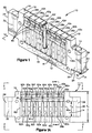
- the sensor array 10 includes a force pin support structure 12 having a first and second opposite side portions 14 and 16, upper and lower end surfaces 18 and 20, and first and second side surfaces 22 and 24. At either side of the support structure 12 there is located a mounting portion 26 and 28 having a throughbore 30 and 32, respectively, through which an attachment bolt (not shown) secures the sensor array 10 to a sensor array mounting frame structure 34 as illustrated in Figure 7 and discussed in detail hereinafter.
- the support structure 12 includes a plurality of cantilever triaxial force pins 36a, 36b, 36c, 36d, 36e, 36f, 36g, 36h(36a-36h), which are located adjacent to each other and are integrally attached to the base portion 40 of the support structure 12.
- Each of the cantilever force pins 36a-36h are identical and therefore only pin 36b, as illustrated in Figures 4, 5, 5A, and 5B, is described in detail since the details of the construction of each triaxial pin are substantially the same. While eight cantilever force pins 36a-36h are illustrated, it is within the terms of the invention to provide more or fewer cantilever force pins depending upon the specific application.
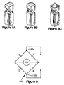
- Cantilever pin 36b has an upper contact surface 42b which can be flat, radiused, convexed or concaved, as shown in Figures 5, 8A 8B, and 8C, respectively.
- the contact surface 42b is flat as shown in Figure 1. The forces being measured, typically those generated in a tire footprint, are transferred to the contact surface of each of the cantilever pins 36a-36h.
- the contact surface 42b (see Figures 4 and 5) of cantilever pin 36b preferably has a rectangular cross-section disposed in a plane perpendicular to the longitudinal axis 44b extending through the cantilever pin, although it is within the terms of the invention to construct the cantilever pins 36a-36h with alternate cross-sections, such as for example, circular and oval cross-sections.
- Pin 36b as shown in Figures 4, 5, 5A and 5B, has an upper portion 46b with a rectangular or square cross-section that has opposite front and rear surfaces. 48b and 50b, respectively, spaced a distance w 1 from each other and opposite side surfaces 52b and 54b spaced a distance t 1 from each other.
- an intermediate portion or region 56b which also has a substantially rectangular or square cross-section that has opposite front and rear surfaces 58b and 60b, respectively, spaced a distance w 2 between each other and opposite side surfaces 62b and 64b, respectively, spaced a distance t 2 .
- the upper portion 46b is contiguous with and integrally attached to the intermediate portion 56b by a plurality of curved surfaces which extend around the perimeter of the force pin, i.e., interconnecting surfaces 48b and 58b, surfaces 50b and 60b, surfaces 52b and 62b, and surfaces 54b and 64b, as best seen in Figure 5A.
- a feature of the invention is that the distances w 1 and t 1 between the opposite surfaces in upper portion 46b are longer, respectively, than the corresponding opposite surfaces in intermediate portion 56b having distances w 2 and t 2 .
- a base portion 66b which also has a substantially rectangular or square cross-section and has opposite front and rear surfaces 72b and 74b spaced a distance w 3 from each other and opposite side surfaces 68b and 70b, respectively, spaced a distance t 3 from each other.
- the intermediate portion 56b is contiguous with and integrally attached to the base portion 66b by a plurality of curved, concave surfaces, as best seen in Figure 5.
- the bottom surface 76b of pin 36b is contiguous with and forms an integral portion of base portion 40 of support structure 12. Since the pins 36a-36h are each attached solely at the bottom of their intermediate portion, i.e. by the concave surfaces to the base portion of the support structure 12, the pins are effectively mounted in a cantilevered manner with respect to base portion 40.
- the triaxial force pin sensor array 10 which includes a plurality of cantilever triaxial force pins 36a-36h, can be machined from a single block of material into a shape as generally shown in Figures 1, 1A, 2 and 3. That is, the block of material is initially shaped into a generally rectangular form having a distance w 4 in the mounting portions 26 and 28 and a height h 1 between the upper end surface 18 and the lower end surface 20, see Figures 1 and 1A.
- a plurality of slits 80 are open at the upper end surface 18 of the support structure 12 and extend to the location 81 which coincides with the upper end of elongated through-slots 82a-82i between adjacent triaxial force pins 36a-36h, as discussed in detail below.
- a plurality of generally oval shaped channels 82a, 82b, 82c, 82d, 82e, 82f, 82g, 82h, 82i (82a-82i) of height h 2 extend completely through the distance w 4 of the support structure 12 as generally shown in Figure 1A.
- Each of these channels 82a-82i reduces the width of pins 36a-36h from the initial spacing of t 1 , as in the upper portion 46b, to the spacing t 2 in the intermediate portion 56b, as shown in Figure 5.
- intermediate portions 56a-56h are rectangular or square about a longitudinal axis 44a-44h (only 44b being illustrated) extending through the pins.
- the intermediate portions 56a-56h each have four curved, concave surfaces extending about the upper end and contiguously joined with the upper portions 46a-46h of the pins 36a-36h, respectively.
- the intermediate portions also have four curved, concave surfaces extending about the lower end which are joined contiguously with the base portions 66a-66h of the pins 36a-36h, respectively.
- the upper slots 90a-90h are parallel with their corresponding lower slots 92a-92h in each pin 36a-36h, respectively.
- the pair of corresponding upper and lower slots for each pin open outwards from opposite facing side surfaces, i.e., 48b and 50b in the example of pin 36b.
- a connecting section 87b extending a distance h 5 between the upper slot 90b and the lower slot 92b, has front and rear facing surfaces 91b and 93b which are recessed inward from the front and rear surfaces 48b and 50b, respectively, of portion 46b and are spaced from each other a distance w 5 which is less than distance w 1 .
- the front and rear facing surfaces 91b and 93b are each in a plane which is parallel to the planes in which the front and rear surfaces 48b and 50b of upper portion 46b are disposed.
- a plurality of blind bores 108a-108h extend up through the lower end 20 of the support structure 12 into each of the cantilever force pins 36a-36h, respectively.
- the blind bores 108a-108h pass through slots 92a-92h and open into slots 90a-90h to provide a passageway to receive electrical signal conducting wires (not shown), as discussed below.
- a pair of spaced through holes 110a-110h are cut through each pin 36a-36h from the front side 58b to the internal bore 108b.
- a pair of through holes 111a-111h are cut from the rear side 60b of the pin and into the internal bore 108b, as shown in Figure 4.
- the sets of spaced through holes 110a-110h and 111a-111h are disposed preferably with their longitudinal axis 113, 115 forming an angle "x" of about 90°.
- the electrical signal conducting wires from the strain gauges, discussed below, are passed through the holes 110a-110h and 111a-111h and into their corresponding bores 108a-108h.
- the material for constructing the support structure 12 is preferably a material selected from the group consisting essentially of aircraft aluminum (A12024) having a material proportional limit of 30,000 psi (2.07 x 10 8 newtons/meter 2 (n/m 2 )) and beryllium copper (BeCu) having a material proportional limit of 100,000 psi. (6.89 x 10 8 n/m 2 ). While both the beryllium copper and the aircraft aluminum are effective for the present design of the pin sensor array 10, the beryllium copper is more advantageous in that it has a more durable wear surface and a higher material proportional limit.
- aircraft aluminum A12024
- BeCu beryllium copper
- the higher material proportional limit is particularly important because it is desirable that as the force pins 36a-36h move, they will naturally return to their original positions without any plastic deformation. This is particularly the case in their movement towards one side 22 or the other side 24 of the support structure 12. With this movement, the pins 36a-36h will abut either against an adjacent pin or possibly side portions 14 and 16 in the case of pins 36a and 36h as a pin is moved from the forces applied thereto.
- any contact with an adjacent force pin or side portions 14, 16 will automatically prevent plastic deformation of the moving pin because the material proportional limit of the sensor array 10 requires a greater degree of movement to achieve plastic deformation than that afforded by the distance between adjacent pins and/or the side portions.
- Another advantage of the beryllium copper is it being a relatively rigid material.
- a still further advantage of the beryllium copper is its natural shielding capability which reduces electromagnetic interference (EMI) and radio frequency (RF) contamination of the sampled data.
- strain gauges 112, 114, 116 are mounted onto each cantilever pin 36a-36h of the force pin support structure 12.
- the first set of strain gauges 112 includes two dual strain gauges 112a and 112b which are mounted onto the side faces of reduced sections 91b and 93b, respectively, as shown in Figures 5 and 5A.
- the second set of strain gauges 114 as shown in Figure 5B which includes four strain gauges 114a, 114b, 114c, 114d are mounted on opposite sides 56b and 60b, respectively, of the pin 36b in the intermediate portion 56b.
- the third set of strain gauges 116 which includes four gauges 116a, 116b, 116c and 116d, are located on the sides 62b and 64b, respectively, of intermediate portion 56b.
- Each of the strain gauge sets 112, 114, and 116 has signal conducting wires (not shown; which, in the case of strain pair 112 are directed through the bore 108b and out the lower open end for attachment to a circuit card 120 as described below.
- the strain gauge sets 114 and 116 have signal conducting wires disposed through bores 110b and 111b which intersect bore 108b so that the wires can also project outward from the open end of bore 108b, as shown in Figure 2.
- circuit card 120 incorporating a plurality of copper strips.
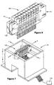
- Two of the triaxial force pin sensor arrays 10 are mounted to opposite surfaces of the circuit card 120, as shown in Figure 6, by conventional means such as screws. This combination of two triaxial force pin sensor arrays with a circuit card therebetween, constitutes a single replaceable force sensor array module 130.
- strain gauges Because of the differences in operating environments, the strain gauges require proper thermal characteristics. Generally, strain gauges can be selected with thermal compensation for steel, copper or aluminum as determined by the material to which the gauges will be attached. Since the material from which the cantilever pins 36a-36h are constructed is preferably beryllium copper, copper compensated gauges will preferably be selected for the sets of strain gauges 112, 114 and 116. The gauges can be mounted by conventional means, such as an epoxy adhesive, to the pins.
- the sealant has a modulus of between about 100 psi (6.89 x 10 5 n/m 2 ) and 1000 psi (6.89 x 10 6 n/m 2 ). It is believed that a modulus below about 100 psi, which would typically be a gel, would lack the adhesion needed to be utilized for the purpose of preventing the accumulation of dirt and dust particles. On the other hand, if the modulus became too high, such as above about 1000 psi, the material would prevent the free movement of the pins as needed.
- a preferred material is a silicone rubber RTV No. 3140 from Dow-Corning.
- a complete triaxial force pin sensor array module 130 would include two triaxial force pin sensor arrays 10 with a circuit card 120 having copper bars disposed there between.
- the signals from the sets of strain gauges 112, 114 and 116 can be taken directly from the sensor array modules 130 and then conditioned and processed in a data collecting system 132, as shown in Figure 7, such as for example a Datronic Model 10K7 measurement and control unit from Datronic Corporation of Miamisburgh, Ohio.
- a single sensor array module 130 can be quickly and easily replaced, with a minimum of downtime, when defective.
- the sensor array module 130 can be constructed with cantilever pins in close proximity in the x-x and y-y directions providing for high density measurements.
- the lateral and tangential (fore-aft) compliance is determined by the placement of the intermediate portion 56a-56h with respect to the base portion 66a-66h, respectively, and the upper portion 46a-46h, respectively. For example, as the intermediate portion 56a-56h is located closer to the bottom surface 76a-76h, respectively, the gain or total displacement of the upper surface 42a-42h increases for a given load. Moreover, the heights of the intermediate portions 56a-56h determines the maximum lateral or tangential load that can be applied before mechanical interference with an adjacent pin is reached.
- the sensitivity for measurement of normal pressures or forces is governed by the selected width w 5 for shear plate members 87a-87h in conjunction with the depth of slots 90a-90h and 92a-92h, respectively.
- the width w 5 of shear plate member 87b as shown in Figures 5 and 5A, is reduced, the response is increased for a given normal load.
- the distances w 2 , t 2 , and h 2 of the intermediate portion 56a-56h also affects the compliance or deflection of the corresponding cantilevered pin 36a-36h with a given lateral or tangential load.
- the diameter of the blind bore 108a-108h also affects the compliance or deflection of its corresponding cantilevered pin.
- the compliance or deflection in the lateral, tangential and normal directions increases for a given load.
- the strain gauge sets 112, 114, 116 are mounted on pins 36a-36h to measure the normal and shear forces generated on the upper contact surfaces 42a-42h of the cantilever pins 36a-36h, respectively.
- a plurality of the sensor array modules 130 can be mounted in a sensor array mounting frame structure 34, only a single module 130 being illustrated in Figure 7, so that the fore-aft direction, i.e. the direction in which the tire being measured rotates across the upper surface of the modules, is in an x-x direction to measure a complete tread element in a single pass. Transverse to the fore-aft direction is the lateral or y-y direction. The normal or load contact pressure is measured in the z-z direction.
- a second embodiment of the invention provides for rotation of the sensor array mounting frame structure 34 such that the x-x and y-y directions are inverted or reversed to measure an entire rib of a tire in a single pass over the triaxial force sensor array modules in box-like structure 34.
- the upper set of strain gauges 112a and 112b measure normal load F z on the shear plate section 87a-87h of the pins 36a-36h, respectively.
- the shear plate section 87a-87h is generally that section between the lower slots 92a-92h and the upper slots 90a-90h of the pins 36a-36h, respectively.
- a load such as a tire
- the pin deflects to change the resistance of strain gauge pairs 112a and 112b of set 112.
- strain gauge sets 114 and 116 respond to movements of the upper contact surface 42a-42h in combinations of fore-aft and/or lateral directions.
- the signals generated by the strain gauge sets 112, 114, 116 are fed to Wheatstone bridges 140, as shown in Figure 9, with resistors A, B, C, D (represented as A-D), one on each side. While each of the resistors A-D, in the preferred embodiment, has a value of about 700 ohms, it is within the terms of the invention to select resistors of different values.
- strain gauge pairs 112a and 112b are each wired in series and each pair has a value of about 700 ohms.
- the Wheatstone bridge 140 is typically excited with a voltage of about 10 volts, however the specific voltage is not a part of the present invention and other voltages can be used. As shown in Figure 9, the output signal is measured across points 142a and 142b, after the Wheatstone bridge has been balanced in a conventional manner.
- Each strain gauge set 112, 114, 116 represent two legs of a Wheatstone bridge, the remaining two legs, 700 ohms each (corresponding to the example of the preferred embodiment), are provided with bridge completion circuitry.
- the triaxial force pin sensor array includes a high density of individual force pin sensors in a modular design that allows for rapid replacement of defective sensor array elements and substantially prevents dirt and contamination from affecting force measurements.
- the triaxial force pin sensor array further reduces electromagnetic interference (EMI) and radio frequency (RF) contamination of the sampled data signals.
- EMI electromagnetic interference
- RF radio frequency
- the triaxial force pin sensor array exhibits uniform response in the normal direction, F z , regardless of contact location with individual triaxial force pins of the sensor array. Further, the triaxial force pin sensor array features mechanical overload protection.
Landscapes
- Physics & Mathematics (AREA)
- General Physics & Mathematics (AREA)
- Force Measurement Appropriate To Specific Purposes (AREA)
Claims (10)
- Dreiachsen-Kraftstiftsensor, umfassend
einen Auslegerkraftstift (36b), der einen oberen Abschnitt (46b) mit einer oberen Kontaktfläche (42b) aufweist, um die auf die obere Kontaktfläche wirkende örtliche Normalkraft und/oder Tangentialkräfte zu messen; und einen Basisabschnitt (66b), der einstückig mit einem Basisabschnitt (40) eines Trägeraufbaus (12) ausgebildet ist;
wobei der Auslegerkraftstift einen Zwischenabschnitt (56b) mit verringertem Querschnitt zwischen dem oberen Abschnitt und dem Basisabschnitt aufweist; und
zwei Schlitze (90b, 92b), die quer durch den oberen Abschnitt des Auslegerkraftstiftes in beabstandeter Beziehung zu der oberen Kontaktfläche angeordnet sind, um ein Scherplattenteilstück (87b) zu bilden, wobei sich jeder der beiden Schlitze zu in entgegengesetzte Richtungen weisenden Seitenflächen (52b, 54b) des Auslegerkraftstiftes öffnet und in anderen Abständen von der oberen Kontaktfläche angeordnet ist. - Dreiachsen-Kraftstiftsensor nach Anspruch 1, wobei der verringerte Querschnitt des Zwischenabschnitts sich um den Umfang des Kraftstiftes herum erstreckt, so daß der Zwischenabschnitt rechtwinklig in bezug auf eine sich in Längsrichtung durch den Auslegerkraftstift hindurch erstreckenden Achse (44b) ist.
- Dreiachsen-Kraftstiftsensor nach Anspruch 1, wobei der Auslegerkraftstift einen im wesentlichen quadratischen Querschnitt in einer Ebene aufweist, die normal zu einer sich in Längsrichtung durch den Auslegerkraftstift hindurch erstreckenden Achse (44b) steht.
- Dreiachsen-Kraftstiftsensor nach Anspruch 1, der ferner eine kreisförmige Bohrung (108b) umfaßt, die sich durch den Auslegerkraftstift hindurch von dem Basisabschnitt zu dem sich an nächsten bei der oberen Kontaktfläche befindlichen Schlitz erstreckt.
- Dreiachsen-Kraftstiftsensor nach Anspruch 1, wobei der Auslegerkraftstift aus einem Material aufgebaut ist, das eine Materialproportionalitätsgrenze von mindestens 30 000 psi (207 MPa) bis 100 000 psi (689 MPa) aufweist.
- Dreiachsen-Kraftstiftsensor nach Anspruch 1, der ferner ein Dreiachsen-Kraftstiftsensor-Array (10) mit einer Vielzahl von Auslegerkraftstiften (36a-36h) umfaßt, die Basisabschnitte (66a-66h) aufweisen, die einstückig mit einem gemeinsamen Basisabschnitt (40) des Trägeraufbaus ausgebildet sind, so daß eine Seitenfläche (52a-52h) von einem der Vielzahl von Auslegerkraftstiften in Richtung einer Seitenfläche (54a - 54h) eines benachbarten Stiftes der Vielzahl von Auslegerkraftstiften weist.
- Dreiachsen-Kraftstiftsensor nach Anspruch 6, der ferner eine Dichtungsmasse um jeden Stift der Vielzahl von Auslegerkraftstiften umfaßt, wobei die Dichtungsmasse einen Modul zwischen 100 psi (0,689 MPa) und 1000 psi (6,89 MPa) aufweist.
- Dreiachsen-Kraftstiftsensor nach Anspruch 6, ferner umfassend:ein Dreiachsen-Kraftstiftsensor-Array-Modul (130) mit zwei Dreiachsen-Kraftstiftsensor-Arrays, die aneinander mit einer dazwischen angeordneten Leiterplatte (120) befestigt sind;einen ersten Satz Dehnungsmesser (112), der an dem Scherplattenteilstück (87a-87h) des oberen Abschnitts (46a-46h) jedes Auslegerkraftstiftes (36a-36h) befestigt ist;einen zweiten und einen dritten Satz Dehnungsmesser (114, 116), die an dem Zwischenabschnitt (56a-56h) jedes Auslegerkraftstiftes befestigt sind; und wobeider erste, der zweite und der dritte Dehnungsmesser durch Elektrodrähte mit der Leiterplatte verbunden sind.
- Verfahren zum Messen von Kräften, mit den Schritten, daß:ein Dreiachsen-Kraftstiftsensor-Array (10) dazu verwendet wird, Kräfte zu messen, die auf eine obere Kontaktfläche (42a-42h) an einem oberen Abschnitt (46a-46h) von einem oder mehreren Auslegerkraftstiften (36a-36h) aufgebracht werden, die an einem entgegengesetzten Basisabschnittende (66a-66h) befestigt sind, das einstückig mit einem Basisabschnitt (40) eines Trägeraufbaus (12) ausgebildet ist, der ein Array (10) von einem oder mehreren benachbarten Auslegerkraftstiften trägt, wobei jeder der Auslegerkraftstifte einen Zwischenabschnitt (56a-56h) mit verringertem Querschnitt zwischen dem oberen Abschnitt und dem Basisabschnitt aufweist und zwei Schlitze (90a-90h, 92a-92h) besitzt, die quer durch den oberen Abschnitt des Auslegerkraftstiftes in beabstandeter Beziehung zu der oberen Kontaktfläche angeordnet sind, um ein Scherplattenteilstück (87a-87h) zu bilden;Scherplattensignale mit einem ersten Satz Dehnungsmesser (112) gemessen werden, die an dem Scherplattenteilstück befestigt sind, wobei die Scherplattensignale der auf die obere Kontaktfläche aufgebrachten Normalkraft (Fz) entsprechen; undzu den oberen Kontaktflächen tangentiale Kräfte mit einem zweiten (114) und einem dritten (116) Satz Dehnungsmesser gemessen werden, die an dem Zwischenabschnitt der Auslegerkraftstifte befestigt sind, wobei die Kraftsignale den in den Längs- und/oder Querrichtungen auf die obere Kontaktfläche aufgebrachten Tangentialkräften entsprechen.
- Verfahren nach Anspruch 9, das ferner die Schritte umfaßt, daß:die Scherplatten- und Kraftsignale von dem ersten, dem zweiten und dem dritten Satz Dehnungsmesser aufbereitet und verarbeitet werden (132); undder örtliche Druck und die Tangentialkräfte, die auf die obere Kontaktfläche von jedem des einen oder der mehreren Auslegerkraftstifte aufgebracht werden, bestimmt werden.
Applications Claiming Priority (1)
| Application Number | Priority Date | Filing Date | Title |
|---|---|---|---|
| PCT/US1998/002186 WO1999040404A1 (en) | 1998-02-04 | 1998-02-04 | Triaxial force pin sensor array |
Publications (2)
| Publication Number | Publication Date |
|---|---|
| EP1053458A1 EP1053458A1 (de) | 2000-11-22 |
| EP1053458B1 true EP1053458B1 (de) | 2002-07-24 |
Family
ID=22266337
Family Applications (1)
| Application Number | Title | Priority Date | Filing Date |
|---|---|---|---|
| EP98906150A Expired - Lifetime EP1053458B1 (de) | 1998-02-04 | 1998-02-04 | Anordnung mit dreiachsigen stabförmigen kraftsensoren |
Country Status (5)
| Country | Link |
|---|---|
| EP (1) | EP1053458B1 (de) |
| JP (1) | JP2002502963A (de) |
| AU (1) | AU6145498A (de) |
| DE (1) | DE69806818T2 (de) |
| WO (1) | WO1999040404A1 (de) |
Families Citing this family (5)
| Publication number | Priority date | Publication date | Assignee | Title |
|---|---|---|---|---|
| US7784363B2 (en) * | 2008-09-30 | 2010-08-31 | Gm Global Technology Operations, Inc. | Phalange tactile load cell |
| JP2011203207A (ja) * | 2010-03-26 | 2011-10-13 | Bridgestone Corp | タイヤの接地特性の測定方法及び測定装置 |
| WO2016063219A2 (en) * | 2014-10-20 | 2016-04-28 | Bührmann Rudolph | A load recording device |
| CN110057482B (zh) * | 2019-02-22 | 2021-02-09 | 中国铁建重工集团股份有限公司道岔分公司 | 尖轨静态密贴力检测装置 |
| JP7287664B2 (ja) * | 2019-06-17 | 2023-06-06 | 国立大学法人 香川大学 | 触覚センサおよび触覚測定方法 |
Family Cites Families (3)
| Publication number | Priority date | Publication date | Assignee | Title |
|---|---|---|---|---|
| US2918816A (en) * | 1958-05-19 | 1959-12-29 | Alfred N Ormond | Force measuring instrument |
| US4986118A (en) * | 1990-03-02 | 1991-01-22 | The Uniroyal Goodrich Tire Company | Apparatus for measuring tire tread force and motion |
| US5445020A (en) * | 1991-11-29 | 1995-08-29 | Exxon Research And Engineering Company | Tire inflation sensor |
-
1998
- 1998-02-04 EP EP98906150A patent/EP1053458B1/de not_active Expired - Lifetime
- 1998-02-04 AU AU61454/98A patent/AU6145498A/en not_active Abandoned
- 1998-02-04 DE DE69806818T patent/DE69806818T2/de not_active Expired - Fee Related
- 1998-02-04 JP JP2000530769A patent/JP2002502963A/ja active Pending
- 1998-02-04 WO PCT/US1998/002186 patent/WO1999040404A1/en active IP Right Grant
Also Published As
| Publication number | Publication date |
|---|---|
| JP2002502963A (ja) | 2002-01-29 |
| EP1053458A1 (de) | 2000-11-22 |
| DE69806818T2 (de) | 2003-02-20 |
| WO1999040404A1 (en) | 1999-08-12 |
| DE69806818D1 (de) | 2002-08-29 |
| AU6145498A (en) | 1999-08-23 |
| WO1999040404A8 (en) | 1999-10-14 |
Similar Documents
| Publication | Publication Date | Title |
|---|---|---|
| US4261429A (en) | Unitized weighing apparatus and method for making such an apparatus | |
| US5663497A (en) | Six component wind tunnel balance | |
| US3771359A (en) | Load cell | |
| US4763531A (en) | Force-torque sensor | |
| US4448083A (en) | Device for measuring components of force and moment in plural directions | |
| US5490427A (en) | Six axis force sensor employing multiple shear strain gages | |
| US20070180722A1 (en) | Sensor module for a probe head of a tactile coordinated measuring machine | |
| JP2988588B2 (ja) | 位置測定装置 | |
| KR20190066627A (ko) | 토크 센서 장치 및 토크를 측정하기 위한 방법 | |
| US6536292B1 (en) | Triaxial force pin sensor array | |
| EP0635703B1 (de) | Lastsensor mit Verschiebungssensor und diese verwendende Wiegevorrichtung | |
| US5201218A (en) | Flexure two shell with separate axial, six component balance | |
| US4181011A (en) | Load cell | |
| US20060107761A1 (en) | Multi-axis load cell body | |
| KR101808928B1 (ko) | 스트레인 전송기 | |
| US6626035B1 (en) | Apparatus and method for tire pressure measurement | |
| CN112747854B (zh) | 一种六维力传感器 | |
| EP1053458B1 (de) | Anordnung mit dreiachsigen stabförmigen kraftsensoren | |
| US7078631B2 (en) | Spring scale | |
| JP2699096B2 (ja) | 測定装置 | |
| US5000037A (en) | Gauging apparatus and method | |
| US20030131672A1 (en) | Load cell | |
| KR100347334B1 (ko) | 고정밀 6축 힘/모멘트 감지센서 | |
| US4419902A (en) | Constant strain load cell | |
| US4146100A (en) | Leverless scale sensor |
Legal Events
| Date | Code | Title | Description |
|---|---|---|---|
| PUAI | Public reference made under article 153(3) epc to a published international application that has entered the european phase |
Free format text: ORIGINAL CODE: 0009012 |
|
| 17P | Request for examination filed |
Effective date: 20000904 |
|
| AK | Designated contracting states |
Kind code of ref document: A1 Designated state(s): DE FR IT |
|
| GRAG | Despatch of communication of intention to grant |
Free format text: ORIGINAL CODE: EPIDOS AGRA |
|
| 17Q | First examination report despatched |
Effective date: 20010718 |
|
| GRAG | Despatch of communication of intention to grant |
Free format text: ORIGINAL CODE: EPIDOS AGRA |
|
| GRAH | Despatch of communication of intention to grant a patent |
Free format text: ORIGINAL CODE: EPIDOS IGRA |
|
| GRAH | Despatch of communication of intention to grant a patent |
Free format text: ORIGINAL CODE: EPIDOS IGRA |
|
| GRAA | (expected) grant |
Free format text: ORIGINAL CODE: 0009210 |
|
| AK | Designated contracting states |
Kind code of ref document: B1 Designated state(s): DE FR IT |
|
| REF | Corresponds to: |
Ref document number: 69806818 Country of ref document: DE Date of ref document: 20020829 |
|
| ET | Fr: translation filed | ||
| PLBE | No opposition filed within time limit |
Free format text: ORIGINAL CODE: 0009261 |
|
| STAA | Information on the status of an ep patent application or granted ep patent |
Free format text: STATUS: NO OPPOSITION FILED WITHIN TIME LIMIT |
|
| 26N | No opposition filed |
Effective date: 20030425 |
|
| PG25 | Lapsed in a contracting state [announced via postgrant information from national office to epo] |
Ref country code: DE Free format text: LAPSE BECAUSE OF NON-PAYMENT OF DUE FEES Effective date: 20030902 |
|
| PG25 | Lapsed in a contracting state [announced via postgrant information from national office to epo] |
Ref country code: FR Free format text: LAPSE BECAUSE OF NON-PAYMENT OF DUE FEES Effective date: 20031031 |
|
| REG | Reference to a national code |
Ref country code: FR Ref legal event code: ST |
|
| PG25 | Lapsed in a contracting state [announced via postgrant information from national office to epo] |
Ref country code: IT Free format text: LAPSE BECAUSE OF NON-PAYMENT OF DUE FEES;WARNING: LAPSES OF ITALIAN PATENTS WITH EFFECTIVE DATE BEFORE 2007 MAY HAVE OCCURRED AT ANY TIME BEFORE 2007. THE CORRECT EFFECTIVE DATE MAY BE DIFFERENT FROM THE ONE RECORDED. Effective date: 20050204 |