EP1052767A2 - Electronically commutated motor - Google Patents
Electronically commutated motor Download PDFInfo
- Publication number
- EP1052767A2 EP1052767A2 EP00109534A EP00109534A EP1052767A2 EP 1052767 A2 EP1052767 A2 EP 1052767A2 EP 00109534 A EP00109534 A EP 00109534A EP 00109534 A EP00109534 A EP 00109534A EP 1052767 A2 EP1052767 A2 EP 1052767A2
- Authority
- EP
- European Patent Office
- Prior art keywords
- phase
- motor
- positioning
- acceleration
- pulse width
- Prior art date
- Legal status (The legal status is an assumption and is not a legal conclusion. Google has not performed a legal analysis and makes no representation as to the accuracy of the status listed.)
- Withdrawn
Links
Images

Classifications
-
- H—ELECTRICITY
- H02—GENERATION; CONVERSION OR DISTRIBUTION OF ELECTRIC POWER
- H02P—CONTROL OR REGULATION OF ELECTRIC MOTORS, ELECTRIC GENERATORS OR DYNAMO-ELECTRIC CONVERTERS; CONTROLLING TRANSFORMERS, REACTORS OR CHOKE COILS
- H02P6/00—Arrangements for controlling synchronous motors or other dynamo-electric motors using electronic commutation dependent on the rotor position; Electronic commutators therefor
- H02P6/20—Arrangements for starting
- H02P6/22—Arrangements for starting in a selected direction of rotation
Definitions
- the invention relates to an electronically commutatable motor, the field windings via semiconductor output stages from an electronic control unit can be energized by means of pulse-modulated control signals and thereby in Stator of the motor generate a rotating field that the permanent magnet rotor of the Motor rotated, at the start of the motor in one Start phase first the position of the rotor to the stator by simultaneous energization two excitation windings positioned and after positioning by switching to other excitation windings in the direction of rotation in Rotational movement is offset.
- the position between the rotor and the stator by evaluating voltages induced in the field windings recognized.
- there are no evaluable voltages when the engine is at a standstill are induced is a position detection when the motor is at a standstill not possible.
- the Motor not ensured, especially not in the desired direction of rotation.
- an electronically commutatable motor can also be started in the correct direction of rotation without position sensors, if in the start phase due to different energization of the field windings first established a certain position between the rotor and stator and only then begins with the usual energization. In doing so at the beginning two excitation windings fully energized at the same time and afterwards takes place to generate the rotating field with the desired direction of rotation required current supply.
- this object is achieved in the starting phase assigned to two neighboring poles during a positioning phase excitation windings wound in the same direction are energized, whereby the Pulse width ratio increases continuously with increasing time, and that the acceleration phase with an increased pulse width ratio connects in which the excitation winding leading in the direction of rotation switched off and the excitation winding wound in the opposite direction is switched on.
- the positioning phase is selected with 1000 to 1500 ms, and that the Acceleration phase with about 10 ms is selected, also a faster one Start-up is guaranteed.
- the effort in the control unit can be kept small by the fact that the start phase with positioning phase and acceleration phase as software is stored in a microcomputer of the control unit.
- FIG. 1 The construction of a 2-leg, 4-pulse engine is shown in Fig. 1. This is to generate a rotating field in the stator for the arrow indicated direction of rotation a control unit STE-PWM required, as Fig. 2 shows.
- the stator has eight poles, between which one is not wound Intermediate pole is arranged.
- the winding direction changes from Partial winding to partial winding and the partial windings of an excitation winding are distributed on poles, between which a pole not occupied by them is arranged.
- the field windings L1 and L3 or L2 and L4 capture the same poles, but opposite each other on each pole Have winding senses.
- the field windings L1 to L4 are switched on and off via semiconductor output stages T1 to T4, that is to say connected to and disconnected from the DC supply voltage U batt .
- the control takes place via pulse-width-modulated control signals and when the engine is started in a start phase consisting of position phase Tp and subsequent acceleration phase Tb, which extends over a predetermined or predeterminable time, such as the time diagram according to FIG. 3 shows.
- the position phase Tp can be, for example, 1200 ms and the acceleration phase Tb can be, for example, 10 ms.
- the pulse width ratio PWV continuously on e.g. 63% increases.
- This position phase Tp is sufficient, the motor in the direction of rotation gently in a predetermined position to bring from which he with the subsequent acceleration phase Tb in the speed is accelerated.
- the pulse width ratio to e.g. 75% increased. So that the start in the desired direction of rotation is continued, the excitation winding L1 switched off in the acceleration phase Tb and the excitation winding L3 when the excitation winding L2 is switched on.
- the excitation windings become L1 to L4 by the control unit STE-PWM in a known manner in successive Control phases determine what leads to the engine running continuously.
- the start phase with the position phase Tp and the acceleration phase Tb are stored as software in a microcomputer of the STE-PWM control unit, like the tax phases of the endurance run.
Landscapes
- Engineering & Computer Science (AREA)
- Power Engineering (AREA)
- Control Of Motors That Do Not Use Commutators (AREA)
Abstract
Description
Die Erfindung betrifft einen elektronisch kommutierbaren Motor, dessen Erregerwicklungen über Halbleiter-Endstufen von einer elektronischen Steuereinheit mittels pulsmodulierter Steuersignale bestrombar sind und dabei im Stator des Motors ein Drehfeld erzeugen, das den Dauermagnet-Rotor des Motors in Drehbewegungen versetzt, bei dem zum Start des Motors in einer Startphase zuerst die Lage des Rotors zum Stator durch gleichzeitige Bestromung zweier Erregerwicklungen positioniert und nach der Positionierung durch Weiterschaltung auf andere Erregerwicklungen in Drehrichtung in Drehbewegung versetzt wird.The invention relates to an electronically commutatable motor, the field windings via semiconductor output stages from an electronic control unit can be energized by means of pulse-modulated control signals and thereby in Stator of the motor generate a rotating field that the permanent magnet rotor of the Motor rotated, at the start of the motor in one Start phase first the position of the rotor to the stator by simultaneous energization two excitation windings positioned and after positioning by switching to other excitation windings in the direction of rotation in Rotational movement is offset.
Bei elektronisch kommutierbaren Motoren Motoren ist es erforderlich, die Stellung des Dauermagnet-Rotors zu dem mit Erregerwicklungen versehenen Stator zu kennen, damit mit der vorgesehenen Kommutierung der Erregerwicklungen der Motor beim Start in der gewünschten Drehrichtung in Drehbewegungen versetzt wird. In the case of electronically commutated motors, it is necessary to use the Position of the permanent magnet rotor in relation to the one provided with field windings Knowing the stator with the intended commutation of the field windings the motor starts rotating in the desired direction of rotation is transferred.
Es sind derartige Motoren mit Lagesensoren bekannt, mit denen die Stellung des abgeschalteten Motors erkennbar gemacht wird. Diese Motoren erfordern nicht nur zusätzliche Lagesensoren, sie bedingen auch einen zusätzlichen Aufwand in der PWM-Steuereinheit.Such motors with position sensors are known with which the position of the switched off engine is made recognizable. These engines require not only additional position sensors, they also require an additional one Effort in the PWM control unit.
Bei Motoren ohne Lagesensoren wird die Stellung zwischen Rotor und Stator durch Auswertung von in den Erregerwicklungen induzierten Spannungen erkannt. Da bei Stillstand des Motors jedoch keine auswertbaren Spannungen induziert werden, ist eine Lageerkennung im Stillstand des Motors nicht möglich. Bei einem Start der Bestimmung ist daher ein Anlaufen des Motors nicht sichergestellt, insbesondere nicht in der gewünschten Drehrichtung.For motors without position sensors, the position between the rotor and the stator by evaluating voltages induced in the field windings recognized. However, there are no evaluable voltages when the engine is at a standstill are induced is a position detection when the motor is at a standstill not possible. When the determination is started, the Motor not ensured, especially not in the desired direction of rotation.
Wie die US 5,327,053 zeigt, kann ein elektronisch kommutierbarer Motor ohne Lagesensoren auch in der richtigen Drehrichtung gestartet werden, wenn in der Startphase durch abweichende Bestromung der Erregerwicklungen erst eine bestimmte Stellung zwischen Rotor und Stator hergestellt und danach erst mit der üblichen Bestromung begonnen wird. Dabei werden zu Beginn zwei Erregerwicklungen gleichzeitig voll bestromt und da-nach erfolgt die zur Erzeugung des Drehfeldes mit der gewünschten Drehrichtung erforderliche Bestromung.As US 5,327,053 shows, an electronically commutatable motor can also be started in the correct direction of rotation without position sensors, if in the start phase due to different energization of the field windings first established a certain position between the rotor and stator and only then begins with the usual energization. In doing so at the beginning two excitation windings fully energized at the same time and afterwards takes place to generate the rotating field with the desired direction of rotation required current supply.
Dabei hat es sich jedoch gezeigt, dass der Anlauf des Motors ruckartig erfolgt und die gewählte Ansteuerung der Erregerwicklungen nur bei relativ geringem Massenträgheitsmoment, hohem Rastmoment und stark bedampftem Motorsystem zu einem sicheren Start führt. However, it has been shown that the motor starts suddenly and the selected control of the excitation windings only with relative low moment of inertia, high cogging torque and heavily steamed Engine system leads to a safe start.
Es ist Aufgabe der Erfindung, bei einem elektronisch kommutierbaren Motor der eingangs erwähnten Art einen sanften, gleichmäßigen Start des Motors auch bei hohem Massenträgheitsmoment, kleinem Rastmoment und geringer Bedämpfung des Motorsystems sicher zu stellen.It is an object of the invention in an electronically commutatable motor the kind mentioned at the beginning a smooth, even start of the engine even with high mass moment of inertia, small cogging torque and less To ensure damping of the motor system.
Diese Aufgabe wird nach der Erfindung dadurch gelöst, das in der Startphase während einer Positionierphase zwei benachbarten Polen zugeordnete gleichsinnig gewickelte Erregerwicklungen bestromt werden, wobei sich das Pulsweitenverhältnis mit zunehmender Zeit kontinuierlich erhöht, und dass sich an die Positionierphase eine Beschleunigungsphase mit erhöhtem Pulsweitenverhältnis anschließt, in der die in Drehrichtung vorauseilende Erregerwicklung abgeschaltet und die zu dieser gegensinnig gewickelte Erregerwicklung dazugeschaltet wird.According to the invention, this object is achieved in the starting phase assigned to two neighboring poles during a positioning phase excitation windings wound in the same direction are energized, whereby the Pulse width ratio increases continuously with increasing time, and that the acceleration phase with an increased pulse width ratio connects in which the excitation winding leading in the direction of rotation switched off and the excitation winding wound in the opposite direction is switched on.
Mit der Positionsphase, in der das Pulsweitenverhältnis kontinuierlich erhöht wird, wird eine sanfte Positionierung und entsprechend auch ein sanfter Anlauf des Motors erreicht, der in der anschließenden Beschleunigungsphase beschleunigt wird und in den Dauerlauf übergeht.With the position phase in which the pulse width ratio increases continuously is a gentle positioning and accordingly also a gentle start of the engine reached in the subsequent acceleration phase is accelerated and passes into the endurance run.
Gute Ergebnisse lassen sich nach einer Ausgestaltung dadurch erreichen, dass die Positionierphase mit 1000 bis 1500 ms gewählt ist, sowie dass die Beschleunigungsphase mit etwa 10 ms gewählt ist, wobei auch ein schneller Anlauf gewährleistet ist.Good results can be achieved after an embodiment by that the positioning phase is selected with 1000 to 1500 ms, and that the Acceleration phase with about 10 ms is selected, also a faster one Start-up is guaranteed.
Der Aufwand in der Steuereinheit läßt sich dabei dadurch klein halten, dass die Startphase mit Positionierphase und Beschleunigungsphase als Software in einem Mikrocomputer der Steuereinheit abgelegt ist. The effort in the control unit can be kept small by the fact that the start phase with positioning phase and acceleration phase as software is stored in a microcomputer of the control unit.
Eine Anpassung der Startbedingungen des Motors läßt sich dadurch auf einfache Weise erreichen, dass die Positionier- und die Beschleunigungsphase automatisch an Betriebszustände angepaßt werden. Dabei ist nach einer Ausgestaltung vorgesehen, dass die Zeiten und das Pulsweitenverhältnis der Positionierphase und der Beschleunigungsphase von der Betriebsspannung der Temperatur und der Toleranz der Motordaten abhängig ist.This makes it easy to adapt the starting conditions of the engine Way that achieve the positioning and acceleration phases can be automatically adapted to operating conditions. It is after one Design provided that the times and the pulse width ratio of the Positioning phase and the acceleration phase of the operating voltage the temperature and the tolerance of the motor data.
Die Erfindung wird anhand eines in den Zeichnungen dargestellten Ausführungsbeispiels näher erläutert. Es zeigen:
- Fig. 1
- einen 2-strangigen, 4-pulsigen Motor,
- Fig. 2
- schematisch die Ansteuerung der vier Erregerwicklungen des Motors nach Fig. 1 und
- Fig. 3
- den Verlauf des Pulsweitenverhältnisses in der Startphase.
- Fig. 1
- a 2-strand, 4-pulse motor,
- Fig. 2
- schematically the control of the four excitation windings of the motor according to FIGS. 1 and
- Fig. 3
- the course of the pulse width ratio in the start phase.
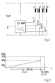
Der Aufbau eines 2-strangigen, 4-pulsigen Motors ist in Fig. 1 dargestellt. Dabei ist zur Erzeugung eines Drehfeldes im Stator für die durch den Pfeil angezeigte Drehrichtung eine Steuereinheit STE-PWM erforderlich, wie Fig. 2 zeigt.The construction of a 2-leg, 4-pulse engine is shown in Fig. 1. This is to generate a rotating field in the stator for the arrow indicated direction of rotation a control unit STE-PWM required, as Fig. 2 shows.
Der Stator weist acht Pole auf, zwischen denen jeweils ein nicht bewickelter Zwischenpol angeordnet ist. Die Erregerwicklungen L1, L2, L3 und L4 sind, wie aus Fig. 1 erkennbar ist, jeweils mit vier Teilwicklungen versehen, die auf vier Pole verteilt sind. Dabei wechselt der Wickelsinn von Teilwicklung zu Teilwicklung und die Teilwicklungen einer Erregerwicklung sind auf Pole verteilt, zwischen denen jeweils ein nicht davon belegter Pol angeordnet ist. Hinzu kommt, dass die Erregerwicklungen L1 und L3 bzw. L2 und L4 dieselben Pole erfassen, jedoch auf jedem Pol jeweils gegenläufige Wickelsinne aufweisen.The stator has eight poles, between which one is not wound Intermediate pole is arranged. The field windings L1, L2, L3 and L4, as can be seen from FIG. 1, each have four partial windings provided, which are distributed on four poles. The winding direction changes from Partial winding to partial winding and the partial windings of an excitation winding are distributed on poles, between which a pole not occupied by them is arranged. In addition, the field windings L1 and L3 or L2 and L4 capture the same poles, but opposite each other on each pole Have winding senses.
Werden diese Erregerwicklungen L1 bis L4 zeitlich nacheinander von der Steuereinheit STE-PWM bestimmt, dann entsteht das gewünschte Drehfeld im Stator.Are these excitation windings L1 to L4 successively from the Control unit STE-PWM determines, then the desired rotating field is created in the stator.
Wie das Schaltbild nach Fig. 2 zeigt, werden die Erregerwicklungen L1 bis L4 über Halbleiter-Endstufen T1 bis T4 ein- und ausgeschaltet, d.h. mit der Versorgungsgleichspannung Ubatt verbunden und von dieser getrennt. Wie in der Steuereinheit STE-PWM angedeutet ist, erfolgt die Ansteuerung über pulsweitenmodulierte Steuersignale und beim Start des Motors in einer aus Positionsphase Tp und anschließender Beschleunigungsphase Tb bestehenden Startphase, die sich über eine vorgegebene oder vorgebbare Zeit erstreckt, wie das Zeitdiagramm nach Fig. 3 zeigt. Dabei kann die Positionsphase Tp z.B. 1200 ms und die Beschleunigungsphase Tb z.B. 10 ms betragen.As the circuit diagram in FIG. 2 shows, the field windings L1 to L4 are switched on and off via semiconductor output stages T1 to T4, that is to say connected to and disconnected from the DC supply voltage U batt . As is indicated in the control unit STE-PWM, the control takes place via pulse-width-modulated control signals and when the engine is started in a start phase consisting of position phase Tp and subsequent acceleration phase Tb, which extends over a predetermined or predeterminable time, such as the time diagram according to FIG. 3 shows. The position phase Tp can be, for example, 1200 ms and the acceleration phase Tb can be, for example, 10 ms.
In der Positionsphase Tp werden die Erregerwicklungen L1 und L2 benachbarter Pole gleichzeitig gleichsinnig bestromt, wobei das Pulsweitenverhältnis PWV kontinuierlich auf z.B. 63 % ansteigt. Diese Positionsphase Tp reicht aus, den Motor in Drehrichtung sanft in eine vorgegebene Position zu bringen, aus der er mit der anschließenden Beschleunigungsphase Tb in der Drehzahl beschleunigt wird. Dabei wird in der Beschleunigungsphase Tb das Pulsweitenverhältnis auf z.B. 75 % erhöht. Damit der Anlauf in der gewünschten Drehrichtung weiter geführt wird, wird die Erregerwicklung L1 in der Beschleunigungsphase Tb abgeschaltet und die Erregerwicklung L3 bei eingeschalteter Erregerwicklung L2 dazugeschaltet.In the position phase Tp, the field windings L1 and L2 become more adjacent Poles simultaneously energized in the same direction, the pulse width ratio PWV continuously on e.g. 63% increases. This position phase Tp is sufficient, the motor in the direction of rotation gently in a predetermined position to bring from which he with the subsequent acceleration phase Tb in the speed is accelerated. In the acceleration phase Tb the pulse width ratio to e.g. 75% increased. So that the start in the desired direction of rotation is continued, the excitation winding L1 switched off in the acceleration phase Tb and the excitation winding L3 when the excitation winding L2 is switched on.
Nach der Beschleunigungsphase Tb werden die Erregerwicklungen L1 bis L4 von der Steuereinheit STE-PWM in bekannter Weise in aufeinander folgenden Steuerphasen bestimmt, was zum Dauerlauf des Motors führt.After the acceleration phase Tb, the excitation windings become L1 to L4 by the control unit STE-PWM in a known manner in successive Control phases determine what leads to the engine running continuously.
Die Startphase mit der Positionsphase Tp und der Beschleunigungsphase Tb sind als Software in einem Mikrocomputer der Steuereinheit STE-PWM abgelegt, wie die Steuerphasen des Dauerlaufes.The start phase with the position phase Tp and the acceleration phase Tb are stored as software in a microcomputer of the STE-PWM control unit, like the tax phases of the endurance run.
Claims (6)
dadurch gekennzeichnet,
characterized,
dadurch gekennzeichnet,
characterized,
dadurch gekennzeichnet,
characterized,
dadurch gekennzeichnet,
characterized,
dadurch gekennzeichnet,
characterized,
Applications Claiming Priority (2)
| Application Number | Priority Date | Filing Date | Title |
|---|---|---|---|
| DE19921849 | 1999-05-11 | ||
| DE1999121849 DE19921849A1 (en) | 1999-05-11 | 1999-05-11 | Electronically commutated motor |
Publications (2)
| Publication Number | Publication Date |
|---|---|
| EP1052767A2 true EP1052767A2 (en) | 2000-11-15 |
| EP1052767A3 EP1052767A3 (en) | 2002-11-20 |
Family
ID=7907799
Family Applications (1)
| Application Number | Title | Priority Date | Filing Date |
|---|---|---|---|
| EP00109534A Withdrawn EP1052767A3 (en) | 1999-05-11 | 2000-05-04 | Electronically commutated motor |
Country Status (2)
| Country | Link |
|---|---|
| EP (1) | EP1052767A3 (en) |
| DE (1) | DE19921849A1 (en) |
Families Citing this family (1)
| Publication number | Priority date | Publication date | Assignee | Title |
|---|---|---|---|---|
| DE10116814A1 (en) * | 2001-04-04 | 2002-11-07 | Bosch Gmbh Robert | Procedure for deriving the rotor position angle |
Citations (5)
| Publication number | Priority date | Publication date | Assignee | Title |
|---|---|---|---|---|
| FR2590423A1 (en) * | 1985-11-21 | 1987-05-22 | Valeo | Method and device for starting an electric motor with electronic commutation |
| US5327053A (en) * | 1992-08-12 | 1994-07-05 | Seagate Technology, Inc. | Apparatus and method for detecting rotor position in a sensorless and brushless DC motor |
| US5466999A (en) * | 1994-08-15 | 1995-11-14 | Maxtor Corporation | Spindle motor start control process and apparatus |
| US5744921A (en) * | 1996-05-02 | 1998-04-28 | Siemens Electric Limited | Control circuit for five-phase brushless DC motor |
| EP0872949A2 (en) * | 1997-04-18 | 1998-10-21 | SISME IMMOBILIARE S.p.A. | Single-phase synchronous permanent-magnet motor arrangement |
Family Cites Families (1)
| Publication number | Priority date | Publication date | Assignee | Title |
|---|---|---|---|---|
| BR8901539A (en) * | 1989-03-27 | 1990-10-30 | Brasil Compressores Sa | PROCESS AND ELECTRONIC CIRCUIT FOR CONTROLLING CURRENT MOTOR CONTROL WITHOUT BRUSHES |
-
1999
- 1999-05-11 DE DE1999121849 patent/DE19921849A1/en not_active Ceased
-
2000
- 2000-05-04 EP EP00109534A patent/EP1052767A3/en not_active Withdrawn
Patent Citations (5)
| Publication number | Priority date | Publication date | Assignee | Title |
|---|---|---|---|---|
| FR2590423A1 (en) * | 1985-11-21 | 1987-05-22 | Valeo | Method and device for starting an electric motor with electronic commutation |
| US5327053A (en) * | 1992-08-12 | 1994-07-05 | Seagate Technology, Inc. | Apparatus and method for detecting rotor position in a sensorless and brushless DC motor |
| US5466999A (en) * | 1994-08-15 | 1995-11-14 | Maxtor Corporation | Spindle motor start control process and apparatus |
| US5744921A (en) * | 1996-05-02 | 1998-04-28 | Siemens Electric Limited | Control circuit for five-phase brushless DC motor |
| EP0872949A2 (en) * | 1997-04-18 | 1998-10-21 | SISME IMMOBILIARE S.p.A. | Single-phase synchronous permanent-magnet motor arrangement |
Also Published As
| Publication number | Publication date |
|---|---|
| EP1052767A3 (en) | 2002-11-20 |
| DE19921849A1 (en) | 2000-11-23 |
Similar Documents
| Publication | Publication Date | Title |
|---|---|---|
| EP1154555B1 (en) | System for electronic commutating a brushless dc motor | |
| EP1076408B1 (en) | Method for starting a brushless DC-motor | |
| DE4009258C2 (en) | Method and electronic control circuit for starting a brushless slip current motor | |
| EP1499008B1 (en) | Method and control system for electronic commutation of a brushless DC motor | |
| DE3544154C2 (en) | ||
| EP1382110B1 (en) | Method and device for determining the rotor position of an electric motor with several motor strings | |
| DE3819062C3 (en) | Process for controlling brushless electric motors and control circuit therefor | |
| EP1071200B1 (en) | Electronically commutatable motor | |
| EP1523090A2 (en) | Method for commutation of a brushless dc motor | |
| EP1734648A1 (en) | Asymmetric excitation of a sensorless and brushless electrical motor | |
| DE3819064C3 (en) | Process for controlling brushless electric motors and control circuit therefor | |
| EP1232561B1 (en) | Method for starting a sensor- and brushless d.c. motor | |
| DE10347208A1 (en) | Operation control device for an electric motor and its control method | |
| DE4404889A1 (en) | Vehicle brushless DC motor drive with electronic speed control | |
| EP1052767A2 (en) | Electronically commutated motor | |
| DE4404926A1 (en) | Vehicle brushless DC motor drive with electronic speed control | |
| DE4122109A1 (en) | Controlling run=up of electronically commutated DC motor - correcting rotor position before supplying dynamic signal to stator winding | |
| EP0685927B1 (en) | Braking method for an inverse rotating synchronous motor powered by a direct current network | |
| DE102019215854A1 (en) | Method for operating a brushless and sensorless multiphase electric motor | |
| EP0246522B1 (en) | Speed control | |
| BE1029061B1 (en) | Method for driving an at least two-phase brushless motor | |
| DE19527983A1 (en) | Control system for switched reluctance motor e.g. in motor vehicle fan or actuator drive - controls application of current to individual phases according to combination of rotor position sensor signals | |
| DE102021101628A1 (en) | Method for driving an at least two-phase brushless motor | |
| DE19953265A1 (en) | Run-up method for brushless DC motor has different winding combinations supplied for bringing rotor into defined position and for rotation of rotor in required direction | |
| EP1670132A2 (en) | Method and arrangement for controlling the synchronisation of a plurality of electronically commutated motors |
Legal Events
| Date | Code | Title | Description |
|---|---|---|---|
| PUAI | Public reference made under article 153(3) epc to a published international application that has entered the european phase |
Free format text: ORIGINAL CODE: 0009012 |
|
| AK | Designated contracting states |
Kind code of ref document: A2 Designated state(s): AT BE CH CY DE DK ES FI FR GB GR IE IT LI LU MC NL PT SE |
|
| AX | Request for extension of the european patent |
Free format text: AL;LT;LV;MK;RO;SI |
|
| PUAL | Search report despatched |
Free format text: ORIGINAL CODE: 0009013 |
|
| AK | Designated contracting states |
Kind code of ref document: A3 Designated state(s): AT BE CH CY DE DK ES FI FR GB GR IE IT LI LU MC NL PT SE |
|
| AX | Request for extension of the european patent |
Free format text: AL;LT;LV;MK;RO;SI |
|
| RIC1 | Information provided on ipc code assigned before grant |
Free format text: 7H 02P 6/22 A, 7H 02P 6/20 B |
|
| 17P | Request for examination filed |
Effective date: 20030520 |
|
| AKX | Designation fees paid |
Designated state(s): DE ES FR GB IT SE |
|
| STAA | Information on the status of an ep patent application or granted ep patent |
Free format text: STATUS: THE APPLICATION IS DEEMED TO BE WITHDRAWN |
|
| 18D | Application deemed to be withdrawn |
Effective date: 20031202 |