EP0246522B1 - Speed control - Google Patents
Speed control Download PDFInfo
- Publication number
- EP0246522B1 EP0246522B1 EP87106747A EP87106747A EP0246522B1 EP 0246522 B1 EP0246522 B1 EP 0246522B1 EP 87106747 A EP87106747 A EP 87106747A EP 87106747 A EP87106747 A EP 87106747A EP 0246522 B1 EP0246522 B1 EP 0246522B1
- Authority
- EP
- European Patent Office
- Prior art keywords
- phase
- motors
- speed control
- control
- rotor
- Prior art date
- Legal status (The legal status is an assumption and is not a legal conclusion. Google has not performed a legal analysis and makes no representation as to the accuracy of the status listed.)
- Expired - Lifetime
Links
Images

Classifications
-
- H—ELECTRICITY
- H02—GENERATION; CONVERSION OR DISTRIBUTION OF ELECTRIC POWER
- H02P—CONTROL OR REGULATION OF ELECTRIC MOTORS, ELECTRIC GENERATORS OR DYNAMO-ELECTRIC CONVERTERS; CONTROLLING TRANSFORMERS, REACTORS OR CHOKE COILS
- H02P6/00—Arrangements for controlling synchronous motors or other dynamo-electric motors using electronic commutation dependent on the rotor position; Electronic commutators therefor
- H02P6/20—Arrangements for starting
-
- H—ELECTRICITY
- H02—GENERATION; CONVERSION OR DISTRIBUTION OF ELECTRIC POWER
- H02P—CONTROL OR REGULATION OF ELECTRIC MOTORS, ELECTRIC GENERATORS OR DYNAMO-ELECTRIC CONVERTERS; CONTROLLING TRANSFORMERS, REACTORS OR CHOKE COILS
- H02P6/00—Arrangements for controlling synchronous motors or other dynamo-electric motors using electronic commutation dependent on the rotor position; Electronic commutators therefor
- H02P6/04—Arrangements for controlling or regulating the speed or torque of more than one motor
-
- H—ELECTRICITY
- H02—GENERATION; CONVERSION OR DISTRIBUTION OF ELECTRIC POWER
- H02P—CONTROL OR REGULATION OF ELECTRIC MOTORS, ELECTRIC GENERATORS OR DYNAMO-ELECTRIC CONVERTERS; CONTROLLING TRANSFORMERS, REACTORS OR CHOKE COILS
- H02P6/00—Arrangements for controlling synchronous motors or other dynamo-electric motors using electronic commutation dependent on the rotor position; Electronic commutators therefor
- H02P6/20—Arrangements for starting
- H02P6/22—Arrangements for starting in a selected direction of rotation
Definitions
- Electronically commutated DC motors are used because of their low noise level and because of their good controllability, e.g. B. with the help of microprocessors, used wherever precision drives are required. They are generally provided with permanent magnet excitation in the rotor or stator part. In this case, multi-pole permanent magnets in ring shape with alternating polarity are preferably used. Separated by an axial or radial air gap, the magnetic poles face the commutatable coils. Depending on the design of the engine, they are designed with two or more branches.
- the motors are equipped with non-contact sensors and associated circuits for the phase position detection of the rotor. These sensors work e.g. B. optoelectronic or with the help of Hall elements.
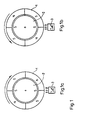
- Fig. 1 shows the orientation of a rotor with any rotor position for startup.
- a two-strand motor with two pairs of magnetic poles is shown as an external rotor.
- Fig. 1a two south poles are generated by this voltage in stator 2.
- the permanent magnets in the rotor 1 the position of which is drawn when the motor is at a standstill, are thereby aligned in the direction of the arrow, which should also be the direction of motor rotation, opposite the south pole in the stator.
- the z. B. consists of a Hall element, the alignment is reported to the control electronics.
- FIG. 1b shows a rotor position when the motor is at a standstill, in which the north pole of the rotor, viewed in the direction of motor rotation, has already been rotated beyond the south pole generated by the stator coils.
- the rotor is aligned in the direction of the arrow in the direction opposite to the direction of rotation of FIG. 1a.
- Fig. 2 shows a block diagram for the synchronous drive of two identical, electronically commutated motors.
- Motors 1 and 2 are three-strand. Both motors are equipped with sensors 3, 4 for the detection of the phase position of the rotors, which work as optocouplers and evaluate a bar code which is attached to the circumference of the rotor.
- the output signal from optocoupler 3 is fed to a converter 5 and the signal from optocoupler 4 to a converter 6.
- the bar code within the converter e.g. B. with the help of a microprocessor, the assignment of the angular position of the rotors can be recognized.
- the converters have three outputs corresponding to the number of strands of the motors, each of which simultaneously outputs a logic 1 signal when the rotor has reached its desired position according to FIG. 1, namely the comparison of the north and south poles.
- Switch 7 is fixed in the switch position shown for phase-synchronous starting and also for phase-synchronous control after starting. This ensures that the control units 8 and 9 at the same time only effect a further switching of the motor commutation via the common control line 10 when a corresponding takeover pulse appears on this line. This pulse is triggered by the output state of an OR circuit 14 in conjunction with the charge state of capacitor 22.
- the OR circuit 14 is activated by a combination of three EX-OR circuits 11, 12, 13, the outputs of which connect to the input of the OR Circuit 14 are connected, driven.
- Each first input of Ex-OR circuits a, b, c is connected to the respective output of converter 5 and every second input of Ex-OR circuits A, B, C is connected to the corresponding output of converter 6.
- This arrangement ensures that the control units 8 and 9 work in quasi parallel operation and cause a synchronous output of the next commutation step.
- the inputs of the control units 8 and 9 are connected to the corresponding output lines of the converters 5 and 6. They are equipped with an internal memory, assigned to each line, since the synchronous operation can only be switched on when the slower motor has reached its desired position. The control signals of the faster motor must therefore be maintained until the slower motor triggers the takeover for the next commutation step at the output of the OR circuit 14.
- control units 8 and 9 are followed by amplifiers 15 to 20 for each engine line, which are designed for the power adjustment for controlling the individual lines.
- Switch 7 is connected to ground for a deliberate asynchronous control of the motors.
- the control units 8 and 9 are switched from the positively synchronized quasi-parallel operation to individual operation.
- the commutation control is carried out separately for each motor, so that e.g. also desired speed differences can be set by means of controller 21.
Abstract
Description
Elektronisch kommutierte Gleichstrommotore werden wegen ihrer geringen Geräuschentwicklung und wegen ihrer guten Steuerbarkeit, z. B. mit Hilfe von Mikroprozessoren, überall dort eingesetzt, wo Präzisionsantriebe gefordert sind. Sie sind im allgemeinen mit Permanentmagneterregung in Rotor- oder Statorteil versehen. Dabei werden vorzugsweise mehrpolige Permanentmagnete in Ringform mit einander abwechselnder Polarität eingesetzt. Über einen axialen oder radialen Luftspalt getrennt, stehen den Magnetpolen die kommutierbaren Spulen gegenüber. Sie sind je nach Auslegung des Motors zwei- oder mehrsträngig ausgeführt. Für die Steuerung sind die Motore mit berührungslos arbeitenden Sensoren und damit verbundenen Schaltungen für die Phasenlageerkennung des Rotors ausgerüstet. Diese Sensoren arbeiten z. B. optoelektronisch oder mit Hilfe von Hallelementen.Electronically commutated DC motors are used because of their low noise level and because of their good controllability, e.g. B. with the help of microprocessors, used wherever precision drives are required. They are generally provided with permanent magnet excitation in the rotor or stator part. In this case, multi-pole permanent magnets in ring shape with alternating polarity are preferably used. Separated by an axial or radial air gap, the magnetic poles face the commutatable coils. Depending on the design of the engine, they are designed with two or more branches. For the control, the motors are equipped with non-contact sensors and associated circuits for the phase position detection of the rotor. These sensors work e.g. B. optoelectronic or with the help of Hall elements.
Bei bestimmten Anwendungcn ist es erforderlich, miteinander zusammenwirkende Motore phasensynchron anlaufen zu lassen und auch während des weiteren Betriebes teilweise phasensynchron zu steuern.In certain applications, it is necessary to start mutually interacting motors phase-synchronously and to control them partly phase-synchronized during further operation.
Es ist Aufgabe der Erfindung, eine derartige phasensynchrone Drehzahlsteuerung aufzuzeigen.It is an object of the invention to demonstrate such a phase-synchronous speed control.
Diese Aufgabe wird gemäß der Erfindung durch die im Anspruch 1 aufgeführten Merkmale gelöst. Vorteilhafte Weiterbildungen der Erfindung sind in den Unteransprüchen beschrieben.This object is achieved according to the invention by the features listed in claim 1. Advantageous developments of the invention are described in the subclaims.
Im Prinzip wird bei Stillstand der Motore für den Anlauf gleichzeitig an gleiche Spulenstränge in quasi Parallelansteuerung so lange eine Spannung gleicher Polung angelegt, bis die Rotore sich so weit ausgerichtet haben, daß der nächste Motorstrang angesteuert werden kann. Die erfolgte Ausrichtung wird von den Sensoren für die Phasenlageerkennung an eine Steuereinheit gemeldet. Erst wenn alle Sensoren übereinstimmend ihre Meldung abgegeben haben, wird durch die Steuereinheit, die eine Speichereinrichtung für die Daten der eingestellten Winkel aufweist, der nächste Spulenstrang angeschaltet, d.h. der nächste Kommutierungsschritt ausgelöst. Eine erneute Weiterschaltung der Spannung an den nächstfolgenden Spulenstrang erfolgt wiederum erst dann, wenn alle Phasenlagenerkenungschaltungen übereinstimmend ihre Meldung abgegeben haben. Das heißt, die Phasenlagemeldung, die zeitlich als letzte erfolgt, bewirkt die Weiterschaltung, so daß die Fortschaltgeschwindigkeit für alle Motore von dem langsamsten Motor abhängig ist.In principle, when the motors are at a standstill, a voltage of the same polarity is applied to the same coil strings in quasi parallel control until the rotors have aligned themselves so far that the next motor train can be controlled. The alignment is reported to a control unit by the sensors for phase position detection. Only when all sensors have submitted their message in agreement is the control unit which has a storage device for the data of the set angles, the next coil strand is switched on, ie the next commutation step is triggered. A renewed switching of the voltage to the next following coil strand again takes place only when all phase position detection circuits have given their message in agreement. This means that the phase position message, which is the last to occur, causes the step to be switched on, so that the advancing speed for all motors depends on the slowest motor.
Die Erfindung wird im folgenden an einem Ausführungsbeispiel anhand der Figuren erläutert.
Darin zeigen:
- Fig. 1
- die Ausrichtung eines Rotors bei beliebiger Rotorstellung für den Anlauf.
- Fig. 2
- ein Blockschaltbild für den synchronen Antrieb von zwei Motoren.
In it show:
- Fig. 1
- the alignment of a rotor with any rotor position for starting.
- Fig. 2
- a block diagram for the synchronous drive of two motors.
Fig. 1 zeigt die Ausrichtung eines Rotors bei beliebiger Rotorstellung für den Anlauf. Es ist ein zweisträngiger Motor mit zwei Magnetpolpaaren als Außenläufer dargestellt. Bei einem geforderten Anlauf mehrerer gleichartiger Motore gleicher Polzahl mit unterschiedlicher Anfangswinkelstellung der einzelnen Rotore ist es erforderlich, von einem definierten Anfangszustand auszugehen. Dieser Zustand wird erreicht, wenn einem gleichartigen Motorstrang aller synchron zu steuernden Motore gleichzeitig eine Spannung gleicher Polung zugeführt wird.Fig. 1 shows the orientation of a rotor with any rotor position for startup. A two-strand motor with two pairs of magnetic poles is shown as an external rotor. When several similar motors of the same number of poles with different starting angular positions of the individual rotors are started, it is necessary to assume a defined initial state. This state is achieved when a voltage of the same polarity is simultaneously supplied to a similar motor train of all motors to be controlled synchronously.
In Fig. 1a werden durch diese Spannung in Stator 2 zwei Südpole erzeugt. Die Permanentmagnete im Rotor 1, dessen Stellung bei Motorstillstand gezeichnet ist, werden dadurch in Pfeilrichtung, die auch gleichzeitig Motordrehrichtung sein soll, dem Südpol im Stator gegenüberstehend ausgerichtet. Durch den Sensor 3, der z. B. aus einem Hallelement besteht, wird die erfolgte Ausrichtung an die Steuerelektronik weitergemeldet.In Fig. 1a, two south poles are generated by this voltage in
Fig. 1b zeigt eine Rotorstellung bei Motorstillstand bei der der Nordpol des Rotors, in Motordrehrichtung gesehen, schon über den durch die Statorspulen erzeugten Südpol hinausgedreht ist. Bei diesem Motor wird eine Ausrichtung des Rotors in Pfeilrichtung entgegen zu der Motordrehrichtung von Fig. 1a erreicht.1b shows a rotor position when the motor is at a standstill, in which the north pole of the rotor, viewed in the direction of motor rotation, has already been rotated beyond the south pole generated by the stator coils. In this motor, the rotor is aligned in the direction of the arrow in the direction opposite to the direction of rotation of FIG. 1a.
Fig. 2 zeigt ein Blockschaltbild für den synchronen Antrieb zweier gleichartiger, elektronisch kommutierter Motore. Die Motore 1 und 2 sind dreisträngig. Beide Motore sind mit Sensoren 3,4 für die Erkennung der Phasenlage der Rotore ausgerüstet, die als Optokoppler arbeiten und einen Strichcode auswerten, der am Rotorumfang angebracht ist. Das Ausgangssignal von Optokoppler 3 wird einem Umsetzer 5 und das Signal von Optokoppler 4 einem Umsetzer 6 zugeführt. Durch Auswertung des Strichcodes innerhalb der Umsetzer, z. B. mit Hilfe eines Mikroprozessors, kann die Zuordnung der Winkellage der Rotore erkannt werden. Die Umsetzer haben entsprechend der Strangzahl der Motore drei Ausgänge, die jeweils dann gleichzeitig ein Signal logisch 1 abgeben, wenn der Rotor seine Sollposition entsprechend Fig. 1, nämlich Gegenüberstellung von Nord- und Südpol, erreicht hat. Für den phasensynchronen Anlauf und auch für eine phasensynchrone Steuerung nach dem Anlauf ist Schalter 7 in der gezeichneten Schalterstellung fixiert. Dadurch wird sichergestellt, daß die Steuergeräte 8 und 9 über die gemeinsame Steuerleitung 10 gleichzeitig erst dann eine Weiterschaltung der Motorkommutierung bewirken, wenn ein entsprechender Übernahmeimpuls auf dieser Leitung erscheint. Ausgelöst wird dieser Impuls von dem Ausgangszustand einer ODER-Schaltung 14 in Verbindung mit dem Ladezustand von Kondensator 22. Die ODER-Schaltung 14 wird durch eine Kombination von drei EX-ODER-Schaltungen 11,12,13, deren Ausgänge mit dem Eingang der ODER-Schaltung 14 verbunden sind, angesteuert. Jeder erste Eingang der Ex-ODER-Schaltungen a,b,c ist mit dem jeweiligen Ausgang von Umsetzer 5 und jeder zweite Eingang der Ex-ODER-Schaltungen A,B,C ist mit dem entsprechenden Ausgang von Umsetzer 6 verbunden. Durch diese Anordnung wird sichergestellt, daß die Steuergeräte 8 und 9 in quasi Parallelbetrieb arbeiten und eine synchrone Ausgabe des nächsten Kommutierungsschrittes bewirken. Die Eingänge der Steuergeräte 8 und 9 sind mit den entsprechenden Ausgangsleitungen der Umsetzer 5 und 6 verbunden. Sie sind mit einem, jedem Strang zugeordneten, internen Speicher versehen, da eine Weiterschaltung bei synchronem Betrieb erst dann erfolgen kann, wenn der langsamere Motor seine Sollstellung erreicht hat. Es müssen also die Aussteuersignale des schnelleren Motors so lange aufrecht erhalten bleiben, bis der langsamere Motor die Übernahme für den nächten Kommutierungsschritt am Ausgang der ODER-Schaltung 14 auslöst.Fig. 2 shows a block diagram for the synchronous drive of two identical, electronically commutated motors.
Den Steuergeräten 8 und 9 sind für jeden Motorstrang Verstärker 15 bis 20 nachgeschaltet, die für die Leistungsanpassung zur Steuerung der einzelnen Stränge ausgelegt sind.The
Für eine gewollte asynchrone Steuerung der Motore wird Schalter 7 nach Masse geschaltet. Dadurch werden die Steuergeräte 8 und 9 aus dem zwangssynchronisierten Quasiparallelbetrieb, in Einzelbetrieb geschaltet. In dieser Schalterstellung wird die Steuerung der Kommutierung direkt für jeden Motor getrennt durchgeführt, so daß z.B. auch gewollte Drehzahlunterschiede mittels Regler 21 eingestellt werden können.Switch 7 is connected to ground for a deliberate asynchronous control of the motors. As a result, the
Im Synchronbetrieb sind dagegen die Drehzahlen der beiden Motore 1 und 2 von der Einstellung von Widerstand 21 nur so lange abhängig,
wie Motor 2 langsamer als Motor 1 läuft.In contrast, in synchronous operation the speeds of the two
how
Claims (4)
- Speed control for identical, two or more phase windings electronically commutated direct current motors (1,2) with sensors (3,4) to recognise the phase relation, characterised in that for synchronised-phase starting a voltage is applied simultaneously to the same phase windings of the motors, and for synchronised-phase control of every further commutation step it is released only when all the sensors signal the same phase relation of the rotors.
- The speed control of claim 1, characterised in that memories (8,9) are provided to transfer the commutation, the memories having a joint control line (10) to trigger the next commutation step.
- The speed control of claim 2, characterised in that a commutation step is triggered by the control line (10) by means of a pulse, by changing the charge of a capacitor (22).
- The speed control of claim 3, characterised in that the charge of the capacitor (22) is changed by changing the state of a logic element.
Priority Applications (1)
| Application Number | Priority Date | Filing Date | Title |
|---|---|---|---|
| AT87106747T ATE79705T1 (en) | 1986-05-17 | 1987-05-08 | SPEED CONTROL. |
Applications Claiming Priority (2)
| Application Number | Priority Date | Filing Date | Title |
|---|---|---|---|
| DE19863616781 DE3616781A1 (en) | 1986-05-17 | 1986-05-17 | SPEED CONTROL |
| DE3616781 | 1986-05-17 |
Publications (3)
| Publication Number | Publication Date |
|---|---|
| EP0246522A2 EP0246522A2 (en) | 1987-11-25 |
| EP0246522A3 EP0246522A3 (en) | 1988-10-26 |
| EP0246522B1 true EP0246522B1 (en) | 1992-08-19 |
Family
ID=6301122
Family Applications (1)
| Application Number | Title | Priority Date | Filing Date |
|---|---|---|---|
| EP87106747A Expired - Lifetime EP0246522B1 (en) | 1986-05-17 | 1987-05-08 | Speed control |
Country Status (7)
| Country | Link |
|---|---|
| EP (1) | EP0246522B1 (en) |
| JP (1) | JPS62277090A (en) |
| KR (1) | KR910000100B1 (en) |
| AT (1) | ATE79705T1 (en) |
| DE (2) | DE3616781A1 (en) |
| ES (1) | ES2033724T3 (en) |
| GR (1) | GR3006264T3 (en) |
Families Citing this family (2)
| Publication number | Priority date | Publication date | Assignee | Title |
|---|---|---|---|---|
| FR2843248B1 (en) * | 2002-07-30 | 2005-01-14 | Moving Magnet Tech Mmt | METHOD FOR CONTROLLING SYNCHRONIZED OPERATION OF AT LEAST TWO POLYPHASE ELECTRIC MOTORS |
| JP5772726B2 (en) * | 2012-05-31 | 2015-09-02 | 株式会社デンソー | Control unit for air conditioner |
Family Cites Families (4)
| Publication number | Priority date | Publication date | Assignee | Title |
|---|---|---|---|---|
| JPS5846885A (en) * | 1981-09-08 | 1983-03-18 | Tipton Mfg Corp | Synchronizing system and device for rotation angle phase of rotation axes of multipurpose motor |
| JPS5858890A (en) * | 1981-10-02 | 1983-04-07 | Toshiba Corp | Speed controller for motor |
| DE3309370A1 (en) * | 1983-03-16 | 1984-09-20 | Zinser Textilmaschinen Gmbh, 7333 Ebersbach | METHOD AND DRIVE DEVICE FOR INFLUENCING THE STARTUP AND LEAKAGE OF TWO ASYNCHRONOUS MOTORS |
| JP2526855B2 (en) * | 1984-04-14 | 1996-08-21 | トヨタ自動車株式会社 | Brushless motor controller |
-
1986
- 1986-05-17 DE DE19863616781 patent/DE3616781A1/en not_active Withdrawn
-
1987
- 1987-05-08 EP EP87106747A patent/EP0246522B1/en not_active Expired - Lifetime
- 1987-05-08 AT AT87106747T patent/ATE79705T1/en not_active IP Right Cessation
- 1987-05-08 DE DE8787106747T patent/DE3781200D1/en not_active Expired - Fee Related
- 1987-05-08 ES ES198787106747T patent/ES2033724T3/en not_active Expired - Lifetime
- 1987-05-16 KR KR1019870004840A patent/KR910000100B1/en not_active IP Right Cessation
- 1987-05-18 JP JP62119142A patent/JPS62277090A/en active Pending
-
1992
- 1992-11-18 GR GR920402622T patent/GR3006264T3/el unknown
Also Published As
| Publication number | Publication date |
|---|---|
| ATE79705T1 (en) | 1992-09-15 |
| ES2033724T3 (en) | 1993-04-01 |
| DE3781200D1 (en) | 1992-09-24 |
| GR3006264T3 (en) | 1993-06-21 |
| EP0246522A3 (en) | 1988-10-26 |
| KR870011745A (en) | 1987-12-26 |
| JPS62277090A (en) | 1987-12-01 |
| EP0246522A2 (en) | 1987-11-25 |
| DE3616781A1 (en) | 1987-11-19 |
| KR910000100B1 (en) | 1991-01-19 |
Similar Documents
| Publication | Publication Date | Title |
|---|---|---|
| EP1154555B1 (en) | System for electronic commutating a brushless dc motor | |
| DE2827340C2 (en) | Drive device with at least two electric motors | |
| DE2837187C2 (en) | ||
| EP0485751B1 (en) | Method for the determination of the speed of a brushless d.c. motor | |
| DE3813130C2 (en) | Digital control unit for a switched reluctance motor | |
| DE3140034C2 (en) | Brushless DC machine | |
| DE10033561B4 (en) | Electronically commutated motor with commutation signal | |
| DE2918493A1 (en) | BRUSHLESS PRINTED DC MOTOR | |
| DE19622049A1 (en) | Start circuit for a brushless DC motor, which suppresses field excitation during changing multiphase commutation states | |
| EP0741449B1 (en) | Electronically commutated motor and process for controlling such a motor | |
| EP0259764B1 (en) | Electronic commutation control circuit for a dc motor | |
| DE3528765C2 (en) | ||
| EP0246522B1 (en) | Speed control | |
| EP1071200A2 (en) | Electronically commutatable motor | |
| EP0780964B1 (en) | Electronically commuted motor | |
| DE3835031C2 (en) | ||
| EP0685927B1 (en) | Braking method for an inverse rotating synchronous motor powered by a direct current network | |
| DE3348465C2 (en) | Washing machine drive using brushless DC motor | |
| DE3218740C2 (en) | ||
| DE4444907A1 (en) | Sensor system with several cascadable sensors esp. for determining actual angle of rotation | |
| DE19524118C2 (en) | Method and device for the speed-dependent control of a multi-phase stepping motor | |
| DE102009055126A1 (en) | Drive device for an electric machine and an engine system | |
| EP1052767A2 (en) | Electronically commutated motor | |
| DE1437154C (en) | Circuit arrangement for synchronizing the speed of a synchronous motor to the frequency of a reference oscillator | |
| EP0140160B1 (en) | Load angle dependent step cycle control for stepping motors |
Legal Events
| Date | Code | Title | Description |
|---|---|---|---|
| PUAI | Public reference made under article 153(3) epc to a published international application that has entered the european phase |
Free format text: ORIGINAL CODE: 0009012 |
|
| AK | Designated contracting states |
Kind code of ref document: A2 Designated state(s): AT BE CH DE ES FR GB GR IT LI LU NL SE |
|
| PUAL | Search report despatched |
Free format text: ORIGINAL CODE: 0009013 |
|
| AK | Designated contracting states |
Kind code of ref document: A3 Designated state(s): AT BE CH DE ES FR GB GR IT LI LU NL SE |
|
| 17P | Request for examination filed |
Effective date: 19890413 |
|
| 17Q | First examination report despatched |
Effective date: 19920116 |
|
| GRAA | (expected) grant |
Free format text: ORIGINAL CODE: 0009210 |
|
| ITF | It: translation for a ep patent filed |
Owner name: BARZANO' E ZANARDO MILANO S.P.A. |
|
| AK | Designated contracting states |
Kind code of ref document: B1 Designated state(s): AT BE CH DE ES FR GB GR IT LI LU NL SE |
|
| REF | Corresponds to: |
Ref document number: 79705 Country of ref document: AT Date of ref document: 19920915 Kind code of ref document: T |
|
| GBT | Gb: translation of ep patent filed (gb section 77(6)(a)/1977) | ||
| REF | Corresponds to: |
Ref document number: 3781200 Country of ref document: DE Date of ref document: 19920924 |
|
| ET | Fr: translation filed | ||
| REG | Reference to a national code |
Ref country code: ES Ref legal event code: FG2A Ref document number: 2033724 Country of ref document: ES Kind code of ref document: T3 |
|
| REG | Reference to a national code |
Ref country code: GR Ref legal event code: FG4A Free format text: 3006264 |
|
| PG25 | Lapsed in a contracting state [announced via postgrant information from national office to epo] |
Ref country code: GB Effective date: 19930508 Ref country code: AT Effective date: 19930508 |
|
| PG25 | Lapsed in a contracting state [announced via postgrant information from national office to epo] |
Ref country code: SE Effective date: 19930509 |
|
| PG25 | Lapsed in a contracting state [announced via postgrant information from national office to epo] |
Ref country code: ES Free format text: LAPSE BECAUSE OF NON-PAYMENT OF DUE FEES Effective date: 19930510 |
|
| PG25 | Lapsed in a contracting state [announced via postgrant information from national office to epo] |
Ref country code: LU Free format text: LAPSE BECAUSE OF NON-PAYMENT OF DUE FEES Effective date: 19930531 Ref country code: LI Effective date: 19930531 Ref country code: CH Effective date: 19930531 Ref country code: BE Effective date: 19930531 |
|
| PGFP | Annual fee paid to national office [announced via postgrant information from national office to epo] |
Ref country code: NL Payment date: 19930531 Year of fee payment: 7 Ref country code: GR Payment date: 19930531 Year of fee payment: 7 |
|
| PLBE | No opposition filed within time limit |
Free format text: ORIGINAL CODE: 0009261 |
|
| STAA | Information on the status of an ep patent application or granted ep patent |
Free format text: STATUS: NO OPPOSITION FILED WITHIN TIME LIMIT |
|
| 26N | No opposition filed | ||
| BERE | Be: lapsed |
Owner name: DEUTSCHE THOMSON-BRANDT G.M.B.H. Effective date: 19930531 |
|
| GBPC | Gb: european patent ceased through non-payment of renewal fee |
Effective date: 19930508 |
|
| PG25 | Lapsed in a contracting state [announced via postgrant information from national office to epo] |
Ref country code: FR Effective date: 19940131 |
|
| REG | Reference to a national code |
Ref country code: CH Ref legal event code: PL |
|
| PG25 | Lapsed in a contracting state [announced via postgrant information from national office to epo] |
Ref country code: DE Effective date: 19940201 |
|
| REG | Reference to a national code |
Ref country code: FR Ref legal event code: ST |
|
| PG25 | Lapsed in a contracting state [announced via postgrant information from national office to epo] |
Ref country code: GR Free format text: THE PATENT HAS BEEN ANNULLED BY A DECISION OF A NATIONAL AUTHORITY Effective date: 19941130 |
|
| PG25 | Lapsed in a contracting state [announced via postgrant information from national office to epo] |
Ref country code: NL Effective date: 19941201 |
|
| NLV4 | Nl: lapsed or anulled due to non-payment of the annual fee | ||
| EUG | Se: european patent has lapsed |
Ref document number: 87106747.6 Effective date: 19931210 |
|
| REG | Reference to a national code |
Ref country code: GR Ref legal event code: MM2A Free format text: 3006264 |
|
| REG | Reference to a national code |
Ref country code: ES Ref legal event code: FD2A Effective date: 19990301 |
|
| PG25 | Lapsed in a contracting state [announced via postgrant information from national office to epo] |
Ref country code: IT Free format text: LAPSE BECAUSE OF NON-PAYMENT OF DUE FEES;WARNING: LAPSES OF ITALIAN PATENTS WITH EFFECTIVE DATE BEFORE 2007 MAY HAVE OCCURRED AT ANY TIME BEFORE 2007. THE CORRECT EFFECTIVE DATE MAY BE DIFFERENT FROM THE ONE RECORDED. Effective date: 20050508 |