EP1052439B1 - Safety valve for fluids - Google Patents
Safety valve for fluids Download PDFInfo
- Publication number
- EP1052439B1 EP1052439B1 EP99500080A EP99500080A EP1052439B1 EP 1052439 B1 EP1052439 B1 EP 1052439B1 EP 99500080 A EP99500080 A EP 99500080A EP 99500080 A EP99500080 A EP 99500080A EP 1052439 B1 EP1052439 B1 EP 1052439B1
- Authority
- EP
- European Patent Office
- Prior art keywords
- valve
- box
- neck
- washer
- spherical
- Prior art date
- Legal status (The legal status is an assumption and is not a legal conclusion. Google has not performed a legal analysis and makes no representation as to the accuracy of the status listed.)
- Expired - Lifetime
Links
Images


Classifications
-
- F—MECHANICAL ENGINEERING; LIGHTING; HEATING; WEAPONS; BLASTING
- F16—ENGINEERING ELEMENTS AND UNITS; GENERAL MEASURES FOR PRODUCING AND MAINTAINING EFFECTIVE FUNCTIONING OF MACHINES OR INSTALLATIONS; THERMAL INSULATION IN GENERAL
- F16K—VALVES; TAPS; COCKS; ACTUATING-FLOATS; DEVICES FOR VENTING OR AERATING
- F16K27/00—Construction of housing; Use of materials therefor
- F16K27/06—Construction of housing; Use of materials therefor of taps or cocks
- F16K27/067—Construction of housing; Use of materials therefor of taps or cocks with spherical plugs
-
- F—MECHANICAL ENGINEERING; LIGHTING; HEATING; WEAPONS; BLASTING
- F16—ENGINEERING ELEMENTS AND UNITS; GENERAL MEASURES FOR PRODUCING AND MAINTAINING EFFECTIVE FUNCTIONING OF MACHINES OR INSTALLATIONS; THERMAL INSULATION IN GENERAL
- F16K—VALVES; TAPS; COCKS; ACTUATING-FLOATS; DEVICES FOR VENTING OR AERATING
- F16K5/00—Plug valves; Taps or cocks comprising only cut-off apparatus having at least one of the sealing faces shaped as a more or less complete surface of a solid of revolution, the opening and closing movement being predominantly rotary
- F16K5/06—Plug valves; Taps or cocks comprising only cut-off apparatus having at least one of the sealing faces shaped as a more or less complete surface of a solid of revolution, the opening and closing movement being predominantly rotary with plugs having spherical surfaces; Packings therefor
- F16K5/0626—Easy mounting or dismounting means
- F16K5/0636—Easy mounting or dismounting means the spherical plug being insertable from the top of the housing
-
- F—MECHANICAL ENGINEERING; LIGHTING; HEATING; WEAPONS; BLASTING
- F16—ENGINEERING ELEMENTS AND UNITS; GENERAL MEASURES FOR PRODUCING AND MAINTAINING EFFECTIVE FUNCTIONING OF MACHINES OR INSTALLATIONS; THERMAL INSULATION IN GENERAL
- F16K—VALVES; TAPS; COCKS; ACTUATING-FLOATS; DEVICES FOR VENTING OR AERATING
- F16K5/00—Plug valves; Taps or cocks comprising only cut-off apparatus having at least one of the sealing faces shaped as a more or less complete surface of a solid of revolution, the opening and closing movement being predominantly rotary
- F16K5/06—Plug valves; Taps or cocks comprising only cut-off apparatus having at least one of the sealing faces shaped as a more or less complete surface of a solid of revolution, the opening and closing movement being predominantly rotary with plugs having spherical surfaces; Packings therefor
- F16K5/0663—Packings
- F16K5/0694—Spindle sealings
Definitions
- the object of the invention that is to be protected by this Patent consists of a Safety valve for fluids.
- the operating means must primarily meet certain safety requirements, particularly making the mobility of flow control members compatible with the valve being altogether sealed in order to prevent potential gas leaks resulting in deflagration or explosion of gas building up therein.
- US 4,026,516 refers to a ball valve stem guide. It discloses a safety valve for fluids being of the so called spherical type.
- the valve comprises a straight or right angle flow and a quarter turn control.
- the valve comprises a box with a fluid flow duct and a neck.
- the neck is provided with two identical longitudinal notches, which lye on a diameter parallel to the axis of the fluid flow duct.
- a straight or right angle flow spherical valve body is provided with a driving shaft.
- the bottom of its axis of longitudinal symmetry is provided with a cylindrical projection.
- valve comprises an intermediate cylindrical tube shaped adjusting part between the shaft driving the valve body and the neck on the box and a washer limiting the turn of a manual control for a valve body.
- the washer is provided with two diameterically opposed radial projections which are housed within the notches in the neck on the box.
- the manual control is provided with two diametrically opposed dissyndrical projections.
- the purpose of the invention constituting the object of this Patent is to enhance the sealing of known valves for controlling the flow in combustible gas lines, ensuring that they are compatible with the required mobility of the control members.
- the valve is of the so-called spherical kind, with a straight or right-angle (90°) fluid flow and with a full to no flow control by means of a quarter-turn of the turning control.
- the means designed to ensure sealing of the valve are the following:
- Figures 1, 2, 3, 5, 6, 7, 8, 9, 10, 17, 18 and 19 show a straight flow valve; figure 17' shows a right-angled valve (90° flow); and the remaining figures show elements valid for both valves.
- the safety valve for fluids protected in this Patent is of the so-called "spherical" kind, with a straight or right-angle (90°) fluid flow and a quarter-turn control.
- the means designed to ensure sealing of the valve in addition to the O-ring seals (9) and (12) are the following:
- This arrangement not only ensures that the valve is sealed but moreover that it is altogether inviolable and even tamper-resistant, and therefore that the valve is safe against deflagration or explosion.
Abstract
Description
- The object of the invention that is to be protected by this Patent consists of a Safety valve for fluids.
- The notion of "safety" contained in the title of the object relates to the valve being sealed as a result of its technical structural and mounting characteristics, for its preferred application is in combustible gas fluid lines.
- The use of combustible (natural, town, butane) gas flow, control or cut-off valves both in mains and in branches thereof for supplying certain appliances (kitchen, heaters, etc.) consuming the same is known and commonly applied.
- In any event, the operating means must primarily meet certain safety requirements, particularly making the mobility of flow control members compatible with the valve being altogether sealed in order to prevent potential gas leaks resulting in deflagration or explosion of gas building up therein.
- US 4,026,516 refers to a ball valve stem guide. It discloses a safety valve for fluids being of the so called spherical type. The valve comprises a straight or right angle flow and a quarter turn control. In particular, the valve comprises a box with a fluid flow duct and a neck. The neck is provided with two identical longitudinal notches, which lye on a diameter parallel to the axis of the fluid flow duct. Further, a straight or right angle flow spherical valve body is provided with a driving shaft. The bottom of its axis of longitudinal symmetry is provided with a cylindrical projection. Further, the valve comprises an intermediate cylindrical tube shaped adjusting part between the shaft driving the valve body and the neck on the box and a washer limiting the turn of a manual control for a valve body. The washer is provided with two diameterically opposed radial projections which are housed within the notches in the neck on the box. The manual control is provided with two diametrically opposed dissymmentrical projections. This document forms the preamble of
claim 1. - The purpose of the invention constituting the object of this Patent is to enhance the sealing of known valves for controlling the flow in combustible gas lines, ensuring that they are compatible with the required mobility of the control members.
- This object is solved by a safety valve for fluids comprising the features of
claim 1. A preferred embodiment is defined bydependent claim 2. - The valve is of the so-called spherical kind, with a straight or right-angle (90°) fluid flow and with a full to no flow control by means of a quarter-turn of the turning control.
- Its structure comprises the following elements:
- A box having a small central cylindrical recess in its bottom inner face for snugly housing a similarly shaped projection existing on the bottom of the valve body, and provided on its neck or top portion with two identical and diametrically opposed notches in the direction of the longitudinal axis, designed to snugly house two diametric projections from the washer limiting the turn of the control to a quarter turn, in order to lock the same.
- A straight or right-angle flow spherical valve body provided on its driving shaft with two O-ring seals and centrally at the bottom end of its axis of longitudinal symmetry, with a cylindrical projection which is snugly housed in the respective recess on the box bottom and serves as a mounting guide and a socket for a rotary connection.
- An intermediate cylindrical tube-shaped adjusting part between the shaft driving the valve body and the box neck, provided with two peripheral throats on the outside surface, each one for housing an O-ring seal.
- A washer limiting the turn of the control to a quarter turn, provided with two diametrically opposed radial projections housed within the notches in the valve neck, to lock the washer.
- A top control, conventionally connected to the valve body shaft, with two diametrically opposed dissymmetrical projections, one being wider and shorter for ease of turning drive pressure and the other one being narrower and longer for a better grip.
-
- The means designed to ensure sealing of the valve are the following:
- Two O-ring seals each inserted in a peripheral throat on the valve body shaft.
- Two O-ring seals each inserted in a peripheral throat on the outside surface of the intermediate adjusting part.
- Two annular elastic seals arranged between the flow passages in the valve box and the surface of the spherical body.
- A inwardly directed top rim on the neck of the box, provided after fitting the washer limiting rotation in its housing. The mechanical step to draw in the edge of the neck can be made because the depth of its notches is greater than the thickness of the washer, which is thus retained in its seat by the rim provided, without being able to come loose even if the internal valve pressure rises, thereby not only ensuring that the valve is sealed but moreover that it is altogether inviolable and even tamper-resistant, and therefore that the valve is safe against deflagration or explosion.
-
- Drawings are attached for a fuller description of the invention and an easier understanding of its formal, structural and functional characteristics and its object, schematically showing various features of a preferred embodiment of the safety valve for fluids subject of this Patent.
- In said drawings, Figures 1, 2, 3, 5, 6, 7, 8, 9, 10, 17, 18 and 19 show a straight flow valve; figure 17' shows a right-angled valve (90° flow); and the remaining figures show elements valid for both valves.
- The following is specifically shown:
- Figures 1 to 6
- show several views of the valve box: Figure 1 is a longitudinal section thereof along line B-B of Figure 3; Figure 2 is a cross-section along line A-A of Figure 5; Figure 3 is a plan view; Figure 4 is an enlarged detail of the profile of the top edge of the neck, before it is drawn in to retain the washer; Figure 5 is a side elevation; and Figure 6 is a perspective.
- Figures 7 to 10
- show several views of the spherical valve body: Figure 7 is a side elevation; Figure 8 is a front elevation; Figure 9 is a section along a diametrical plane, in the longitudinal direction of the straight flow opening; and Figure 10 is a perspective.
- Figures 11 to 14
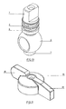
- show several views of the top manual control: Figure 11 is a perspective; Figure 12 is a lower plan; Figure 13 is a section along a longitudinal plane in the direction of two drive projections; and Figure 14 is a top plan view.
- Figures 15 and 16
- show the washer limiting the turning of the control to a quarter turn: Figure 15 is a perspective and Figure 16 a plan.
- Figures 17 and 18
- show a same longitudinal section of the mounted straight flow valve: Figure 17 is a front projection and Figure 18 a perspective. Figure 17' is a longitudinal section of the right-angle valve.
- Figure 19
- is an exploded view of the structural valve components.
- The construction and mounting of the safety valve for fluids constituting the object of the invention is described hereinafter in order to clearly show the nature and scope of its advantageous application with reference to the drawings which show a preferred embodiment of said object for informative purposes.
- The safety valve for fluids protected in this Patent is of the so-called "spherical" kind, with a straight or right-angle (90°) fluid flow and a quarter-turn control.
- Its structure comprises:
- A box (1) having a small central cylindrical recess (2) in its bottom inner face, snugly housing a similarly shaped projection (3) existing on the bottom of the spherical body (4), whereas its neck (5) is provided with two identical longitudinal notches (6) lying at the ends of a diameter parallel to the axis of the fluid flow duct, their depth being greater than the thickness of the washer (13).
- A straight or right-angle (90°) flow spherical valve body (4) provided
on its driving shaft (7) with two peripheral throats (8), each one
to house an O-ring seal (9), whereas the bottom end of its axis of
longitudinal symmetry is provided with a cylindrical projection
(3).
- An intermediate cylindrical tube-shaped adjusting part (10) between the shaft (7) driving the body (4) and the neck (5) on the box (1), provided with two peripheral throats (11), each one to house an O-ring seal (12).
- A washer (13) limiting the turn of the control, provided with two diametrically opposed radial projections (14) housed within the notches (6) in the valve neck (5).
- A manual control (15) provided with two diametrically opposed dissymmetrical projections, one (16) being wider and shorter and the other one (17) being narrower and longer.
-
- The means designed to ensure sealing of the valve in addition to the O-ring seals (9) and (12) are the following:
- Two annular elastic seals (18) arranged between the flow passages in the box (1) and the surface of the spherical body (4).
- A rim (19) on the neck (5) of the box (1) provided by drawing in its top edge after fitting the washer (13) in its housing, thereby for it to be retained therein even if the internal valve pressure rises.
-
- This arrangement not only ensures that the valve is sealed but moreover that it is altogether inviolable and even tamper-resistant, and therefore that the valve is safe against deflagration or explosion.
Claims (2)
- A safety valve for fluids, being of the so-called "spherical" kind, with a straight or right-angle (90°) flow and a quarter-turn control, comprising:characterized in thata box (1) with a fluid flow duct and a neck (5);the neck (5) being provided with two identical longitudinal notches (6) lying at the ends of a diameter parallel to the axis of the fluid flow duct;a straight or right-angle (90°) flow spherical valve body (4) provided with a driving shaft (7), whereas the bottom end of its axis of longitudinal symmetry is provided with a cylindrical projection (3);an intermediate cylindrical tube-shaped adjusting part (10) between the shaft (7) driving the valve body (4) and the neck (5) on the box (1);a washer (13) limiting the turn of a manual control (15) for the valve body (4), provided with two diametrically opposed radial projections (14) housed within the notches (6) in the neck (5) on the box (1);the manual control (15) provided with two diametrically opposed dissymmetrical projections;
the box (1) has a small central cylindrical recess (2) in its bottom inner face, snugly housing a similarly shaped projection (3) existing on the bottom of the spherical valve body (4);
the depth of the two identical longitudinal notches (6) is greater than the thickness of the washer (13);
the driving shaft (7) has two peripheral throats (8), each one to house an O-ring seal (9);
the intermediate cylindrical tube-shaped adjusting part (10) is provided with two peripheral throats (11) on the outer diameter, each one to house an O-ring seal (12); and
one (16) of the projections of the manual control is wider and shorter and the other one (17) is narrower and longer. - A safety valve for fluids according to Claim 1,
characterized in that the means designed to ensure sealing of the valve in addition to the O-ring seals (9) and (12) are the following: two annular elastic seals (18) arranged between the flow passages in the box (1) and the surface of the spherical body (4); a rim (19) on the neck (5) of the box (1) provided by drawing in its top edge after fitting the washer (13) in its housing, thereby for it to be retained therein even if the internal valve pressure rises, thereby not only ensuring that the valve is sealed but moreover that it is altogether inviolable and even tamper-resistant, and therefore that the valve is safe against deflagration or explosion.
Priority Applications (9)
| Application Number | Priority Date | Filing Date | Title |
|---|---|---|---|
| PT101871A PT101871A (en) | 1996-05-07 | 1996-05-07 | Parallel-branch and -passage valve for gaseous fluid conduits |
| BR9602593A BR9602593A (en) | 1996-05-07 | 1996-06-03 | Optimized valve for fluids |
| EP99500080A EP1052439B1 (en) | 1996-05-07 | 1999-05-13 | Safety valve for fluids |
| ES99500080T ES2227991T3 (en) | 1996-05-07 | 1999-05-13 | SAFETY VALVE FOR FLUIDS. |
| PT99500080T PT1052439E (en) | 1996-05-07 | 1999-05-13 | FLUID SAFETY VALVE |
| AT99500080T ATE273470T1 (en) | 1996-05-07 | 1999-05-13 | SAFETY VALVE FOR FLUID |
| DE69919328T DE69919328D1 (en) | 1996-05-07 | 1999-05-13 | Safety valve for fluids |
| US09/313,475 US6431520B1 (en) | 1996-05-07 | 1999-05-17 | Safety valve for fluids |
| SA99200732A SA99200732B1 (en) | 1996-05-07 | 1999-11-03 | SAFETY VALVE FOR FLUIDS |
Applications Claiming Priority (4)
| Application Number | Priority Date | Filing Date | Title |
|---|---|---|---|
| PT101871A PT101871A (en) | 1996-05-07 | 1996-05-07 | Parallel-branch and -passage valve for gaseous fluid conduits |
| BR9602593A BR9602593A (en) | 1996-05-07 | 1996-06-03 | Optimized valve for fluids |
| EP99500080A EP1052439B1 (en) | 1996-05-07 | 1999-05-13 | Safety valve for fluids |
| US09/313,475 US6431520B1 (en) | 1996-05-07 | 1999-05-17 | Safety valve for fluids |
Publications (2)
| Publication Number | Publication Date |
|---|---|
| EP1052439A1 EP1052439A1 (en) | 2000-11-15 |
| EP1052439B1 true EP1052439B1 (en) | 2004-08-11 |
Family
ID=27425258
Family Applications (1)
| Application Number | Title | Priority Date | Filing Date |
|---|---|---|---|
| EP99500080A Expired - Lifetime EP1052439B1 (en) | 1996-05-07 | 1999-05-13 | Safety valve for fluids |
Country Status (8)
| Country | Link |
|---|---|
| US (1) | US6431520B1 (en) |
| EP (1) | EP1052439B1 (en) |
| AT (1) | ATE273470T1 (en) |
| BR (1) | BR9602593A (en) |
| DE (1) | DE69919328D1 (en) |
| ES (1) | ES2227991T3 (en) |
| PT (2) | PT101871A (en) |
| SA (1) | SA99200732B1 (en) |
Families Citing this family (13)
| Publication number | Priority date | Publication date | Assignee | Title |
|---|---|---|---|---|
| EP1429063A1 (en) * | 2002-12-09 | 2004-06-16 | Valvulas Arco, S.L. | System for retaining internal components in valves |
| DE60208060T2 (en) * | 2002-12-24 | 2006-06-22 | Techspace Aero S.A. | control valve |
| US7373953B2 (en) * | 2003-08-11 | 2008-05-20 | Oatey Co. | Valve assembly |
| US8555923B1 (en) * | 2003-08-11 | 2013-10-15 | Oatey Co. | Valve assembly |
| CA2449372C (en) * | 2003-11-14 | 2007-10-16 | G. Robert Muddiman | Cylindrical plug valve |
| US20060037655A1 (en) * | 2004-08-17 | 2006-02-23 | Ferrer Beltran Jose M | Three-way valve with independent quarter-turn outlets |
| US7611324B2 (en) * | 2006-11-30 | 2009-11-03 | General Electric Company | Method and system to facilitate enhanced local cooling of turbine engines |
| US20080283699A1 (en) * | 2007-05-15 | 2008-11-20 | Wuu-Cheau Jou | Stand for a drying gun supporting frame |
| CN201129493Y (en) * | 2007-12-18 | 2008-10-08 | 谭仲禧 | Control ball valve |
| WO2011127362A2 (en) * | 2010-04-08 | 2011-10-13 | Enerco Group, Inc. | Fuel selector valve |
| US9777860B2 (en) | 2012-08-13 | 2017-10-03 | Broen A/S | Valve housing with collared spindle guide |
| ES2505315B1 (en) * | 2013-03-08 | 2015-09-25 | Válvulas Arco, S.L. | PERFECTED THREE-WAY VALVE STRUCTURE |
| DK177973B1 (en) * | 2013-09-09 | 2015-02-09 | Broen As | Method of manufacturing a valve housing with spindle and valve housing |
Family Cites Families (16)
| Publication number | Priority date | Publication date | Assignee | Title |
|---|---|---|---|---|
| US2919886A (en) * | 1953-09-03 | 1960-01-05 | Gordon F Hurst | Ball valve |
| US3096966A (en) * | 1959-07-23 | 1963-07-09 | Hills Mccanna Co | Sealed ball valve |
| FR1429302A (en) * | 1964-11-12 | 1966-02-25 | Auxiliaire De L Ind Et Des Min | Further development of ball valves |
| US3584833A (en) * | 1969-06-20 | 1971-06-15 | Gen Ind Inc | Sheet metal two-part valve housing |
| US4026516A (en) * | 1970-05-28 | 1977-05-31 | Whitey Research Tool Co. | Ball valve stem guide |
| FR2335766A1 (en) * | 1975-12-18 | 1977-07-15 | Legris France Sa | IMPROVEMENT OF ROTATING ROD VALVES |
| US4345738A (en) * | 1980-08-25 | 1982-08-24 | Grove Valve And Regulator Company | Fire safe seal |
| US4753418A (en) * | 1987-07-13 | 1988-06-28 | Consolidated Ceramic Limited | Non-rise faucet assembly having stem locator cap to insure proper sealing |
| IT1232361B (en) * | 1989-04-05 | 1992-01-28 | Ferrero Rubinetteria S N C Di | PERFECTED BALL VALVE FOR REFRIGERATION SYSTEMS |
| DE69028018T2 (en) * | 1989-12-19 | 1996-12-05 | Asahi Organic Chem Ind | BALL VALVE |
| US5010917A (en) * | 1990-04-02 | 1991-04-30 | Kohler Co. | Fluid control valve |
| US5042529A (en) * | 1990-12-21 | 1991-08-27 | Wan Tiao Yeh | Structure of water flow regulating device |
| US5246203A (en) * | 1992-06-29 | 1993-09-21 | M&M Supply Co. | Oilfield valve |
| US5263685A (en) * | 1992-07-13 | 1993-11-23 | Orbit Valve Company | Valve seat |
| US5577709A (en) * | 1995-10-17 | 1996-11-26 | Henry Valve Company | Stem seal configuration for ball valves |
| US5735307A (en) * | 1996-02-27 | 1998-04-07 | Dahl Brothers Canada Limited | Valve interchangeable between angle and straight |
-
1996
- 1996-05-07 PT PT101871A patent/PT101871A/en active IP Right Grant
- 1996-06-03 BR BR9602593A patent/BR9602593A/en not_active IP Right Cessation
-
1999
- 1999-05-13 AT AT99500080T patent/ATE273470T1/en not_active IP Right Cessation
- 1999-05-13 EP EP99500080A patent/EP1052439B1/en not_active Expired - Lifetime
- 1999-05-13 DE DE69919328T patent/DE69919328D1/en not_active Expired - Lifetime
- 1999-05-13 PT PT99500080T patent/PT1052439E/en unknown
- 1999-05-13 ES ES99500080T patent/ES2227991T3/en not_active Expired - Lifetime
- 1999-05-17 US US09/313,475 patent/US6431520B1/en not_active Expired - Lifetime
- 1999-11-03 SA SA99200732A patent/SA99200732B1/en unknown
Also Published As
| Publication number | Publication date |
|---|---|
| ES2227991T3 (en) | 2005-04-01 |
| SA99200732B1 (en) | 2006-09-09 |
| DE69919328D1 (en) | 2004-09-16 |
| EP1052439A1 (en) | 2000-11-15 |
| US6431520B1 (en) | 2002-08-13 |
| ATE273470T1 (en) | 2004-08-15 |
| PT101871A (en) | 1997-12-31 |
| PT1052439E (en) | 2005-01-31 |
| BR9602593A (en) | 1998-10-06 |
Similar Documents
| Publication | Publication Date | Title |
|---|---|---|
| EP1052439B1 (en) | Safety valve for fluids | |
| US4809949A (en) | Plug valve | |
| US5010917A (en) | Fluid control valve | |
| US9574669B2 (en) | Butterfly valve assembly | |
| US4609177A (en) | Valve | |
| JPH01283481A (en) | Flow control valve | |
| RU2154214C2 (en) | Valve assembly with improved valve seat | |
| US9115812B2 (en) | Plug valve with a spring biased plug | |
| JPS63270984A (en) | Ball valve | |
| US3802457A (en) | Plug valve with combined plug operating, retaining, and removal means | |
| ES2199769T3 (en) | FAUCET | |
| US3727879A (en) | Shut-off valve | |
| US5881999A (en) | Water shutoff valve assembly | |
| US20060202149A1 (en) | Cylindrical plug valve | |
| EP1018614B1 (en) | Plug valve | |
| US20050109969A1 (en) | Stem construction for rotatable valve body | |
| CN201368209Y (en) | Manual butterfly valve | |
| NO811373L (en) | FLUIDUMSTROEMSTYREVENTIL. | |
| JPH09210226A (en) | Opening/closing valve | |
| AU578337B2 (en) | Single handle mixing faucet with inlet reversing member | |
| ES2832584B2 (en) | Shut-off valve or fluid regulation | |
| US3814379A (en) | Rotary valve with anti-corrosion and torque controlling means | |
| KR200187889Y1 (en) | Hose connecting apparatus of rotation-form | |
| KR200364837Y1 (en) | A locking device for sealing gas | |
| GB2040408A (en) | Rotary plug valve |
Legal Events
| Date | Code | Title | Description |
|---|---|---|---|
| PUAI | Public reference made under article 153(3) epc to a published international application that has entered the european phase |
Free format text: ORIGINAL CODE: 0009012 |
|
| AK | Designated contracting states |
Kind code of ref document: A1 Designated state(s): AT BE CH CY DE DK ES FI FR GB GR IE IT LI LU MC NL PT SE |
|
| AX | Request for extension of the european patent |
Free format text: AL PAYMENT 19990610;LT PAYMENT 19990610;LV PAYMENT 19990610;MK PAYMENT 19990610;RO PAYMENT 19990610;SI PAYMENT 19990610 |
|
| 17P | Request for examination filed |
Effective date: 20010406 |
|
| AKX | Designation fees paid |
Free format text: AT BE CH CY DE DK ES FI FR GB GR IE IT LI LU MC NL PT SE |
|
| AXX | Extension fees paid |
Free format text: AL PAYMENT 19990610;LT PAYMENT 19990610;LV PAYMENT 19990610;MK PAYMENT 19990610;RO PAYMENT 19990610;SI PAYMENT 19990610 |
|
| 17Q | First examination report despatched |
Effective date: 20030519 |
|
| GRAP | Despatch of communication of intention to grant a patent |
Free format text: ORIGINAL CODE: EPIDOSNIGR1 |
|
| GRAS | Grant fee paid |
Free format text: ORIGINAL CODE: EPIDOSNIGR3 |
|
| GRAA | (expected) grant |
Free format text: ORIGINAL CODE: 0009210 |
|
| AK | Designated contracting states |
Kind code of ref document: B1 Designated state(s): AT BE CH CY DE DK ES FI FR GB GR IE IT LI LU MC NL PT SE |
|
| AX | Request for extension of the european patent |
Extension state: AL LT LV MK RO SI |
|
| PG25 | Lapsed in a contracting state [announced via postgrant information from national office to epo] |
Ref country code: NL Free format text: LAPSE BECAUSE OF FAILURE TO SUBMIT A TRANSLATION OF THE DESCRIPTION OR TO PAY THE FEE WITHIN THE PRESCRIBED TIME-LIMIT Effective date: 20040811 Ref country code: LI Free format text: LAPSE BECAUSE OF FAILURE TO SUBMIT A TRANSLATION OF THE DESCRIPTION OR TO PAY THE FEE WITHIN THE PRESCRIBED TIME-LIMIT Effective date: 20040811 Ref country code: FI Free format text: LAPSE BECAUSE OF FAILURE TO SUBMIT A TRANSLATION OF THE DESCRIPTION OR TO PAY THE FEE WITHIN THE PRESCRIBED TIME-LIMIT Effective date: 20040811 Ref country code: CH Free format text: LAPSE BECAUSE OF FAILURE TO SUBMIT A TRANSLATION OF THE DESCRIPTION OR TO PAY THE FEE WITHIN THE PRESCRIBED TIME-LIMIT Effective date: 20040811 Ref country code: BE Free format text: LAPSE BECAUSE OF FAILURE TO SUBMIT A TRANSLATION OF THE DESCRIPTION OR TO PAY THE FEE WITHIN THE PRESCRIBED TIME-LIMIT Effective date: 20040811 Ref country code: AT Free format text: LAPSE BECAUSE OF FAILURE TO SUBMIT A TRANSLATION OF THE DESCRIPTION OR TO PAY THE FEE WITHIN THE PRESCRIBED TIME-LIMIT Effective date: 20040811 |
|
| REG | Reference to a national code |
Ref country code: GB Ref legal event code: FG4D |
|
| REG | Reference to a national code |
Ref country code: CH Ref legal event code: EP |
|
| REG | Reference to a national code |
Ref country code: IE Ref legal event code: FG4D |
|
| REF | Corresponds to: |
Ref document number: 69919328 Country of ref document: DE Date of ref document: 20040916 Kind code of ref document: P |
|
| PG25 | Lapsed in a contracting state [announced via postgrant information from national office to epo] |
Ref country code: SE Free format text: LAPSE BECAUSE OF FAILURE TO SUBMIT A TRANSLATION OF THE DESCRIPTION OR TO PAY THE FEE WITHIN THE PRESCRIBED TIME-LIMIT Effective date: 20041111 Ref country code: GR Free format text: LAPSE BECAUSE OF FAILURE TO SUBMIT A TRANSLATION OF THE DESCRIPTION OR TO PAY THE FEE WITHIN THE PRESCRIBED TIME-LIMIT Effective date: 20041111 Ref country code: DK Free format text: LAPSE BECAUSE OF FAILURE TO SUBMIT A TRANSLATION OF THE DESCRIPTION OR TO PAY THE FEE WITHIN THE PRESCRIBED TIME-LIMIT Effective date: 20041111 |
|
| PG25 | Lapsed in a contracting state [announced via postgrant information from national office to epo] |
Ref country code: DE Free format text: LAPSE BECAUSE OF FAILURE TO SUBMIT A TRANSLATION OF THE DESCRIPTION OR TO PAY THE FEE WITHIN THE PRESCRIBED TIME-LIMIT Effective date: 20041112 |
|
| LTIE | Lt: invalidation of european patent or patent extension |
Effective date: 20040811 |
|
| REG | Reference to a national code |
Ref country code: PT Ref legal event code: SC4A Effective date: 20041110 |
|
| NLV1 | Nl: lapsed or annulled due to failure to fulfill the requirements of art. 29p and 29m of the patents act | ||
| REG | Reference to a national code |
Ref country code: CH Ref legal event code: PL |
|
| REG | Reference to a national code |
Ref country code: ES Ref legal event code: FG2A Ref document number: 2227991 Country of ref document: ES Kind code of ref document: T3 |
|
| PG25 | Lapsed in a contracting state [announced via postgrant information from national office to epo] |
Ref country code: LU Free format text: LAPSE BECAUSE OF NON-PAYMENT OF DUE FEES Effective date: 20050513 Ref country code: IE Free format text: LAPSE BECAUSE OF NON-PAYMENT OF DUE FEES Effective date: 20050513 Ref country code: GB Free format text: LAPSE BECAUSE OF NON-PAYMENT OF DUE FEES Effective date: 20050513 Ref country code: CY Free format text: LAPSE BECAUSE OF FAILURE TO SUBMIT A TRANSLATION OF THE DESCRIPTION OR TO PAY THE FEE WITHIN THE PRESCRIBED TIME-LIMIT Effective date: 20050513 |
|
| PG25 | Lapsed in a contracting state [announced via postgrant information from national office to epo] |
Ref country code: MC Free format text: LAPSE BECAUSE OF NON-PAYMENT OF DUE FEES Effective date: 20050531 |
|
| PLBE | No opposition filed within time limit |
Free format text: ORIGINAL CODE: 0009261 |
|
| STAA | Information on the status of an ep patent application or granted ep patent |
Free format text: STATUS: NO OPPOSITION FILED WITHIN TIME LIMIT |
|
| ET | Fr: translation filed | ||
| 26N | No opposition filed |
Effective date: 20050512 |
|
| GBPC | Gb: european patent ceased through non-payment of renewal fee |
Effective date: 20050513 |
|
| REG | Reference to a national code |
Ref country code: IE Ref legal event code: MM4A |
|
| PGFP | Annual fee paid to national office [announced via postgrant information from national office to epo] |
Ref country code: PT Payment date: 20100311 Year of fee payment: 12 |
|
| PGFP | Annual fee paid to national office [announced via postgrant information from national office to epo] |
Ref country code: FR Payment date: 20100519 Year of fee payment: 12 Ref country code: ES Payment date: 20100625 Year of fee payment: 12 |
|
| PGFP | Annual fee paid to national office [announced via postgrant information from national office to epo] |
Ref country code: IT Payment date: 20100505 Year of fee payment: 12 |
|
| REG | Reference to a national code |
Ref country code: PT Ref legal event code: MM4A Free format text: LAPSE DUE TO NON-PAYMENT OF FEES Effective date: 20111114 |
|
| PG25 | Lapsed in a contracting state [announced via postgrant information from national office to epo] |
Ref country code: PT Free format text: LAPSE BECAUSE OF NON-PAYMENT OF DUE FEES Effective date: 20111114 |
|
| REG | Reference to a national code |
Ref country code: FR Ref legal event code: ST Effective date: 20120131 |
|
| PG25 | Lapsed in a contracting state [announced via postgrant information from national office to epo] |
Ref country code: IT Free format text: LAPSE BECAUSE OF NON-PAYMENT OF DUE FEES Effective date: 20110513 |
|
| PG25 | Lapsed in a contracting state [announced via postgrant information from national office to epo] |
Ref country code: FR Free format text: LAPSE BECAUSE OF NON-PAYMENT OF DUE FEES Effective date: 20110531 |
|
| REG | Reference to a national code |
Ref country code: ES Ref legal event code: FD2A Effective date: 20131030 |
|
| PG25 | Lapsed in a contracting state [announced via postgrant information from national office to epo] |
Ref country code: ES Free format text: LAPSE BECAUSE OF NON-PAYMENT OF DUE FEES Effective date: 20110514 |