EP1052308A2 - Verfahren zur Beschichtung eines Wärmetauschers - Google Patents
Verfahren zur Beschichtung eines Wärmetauschers Download PDFInfo
- Publication number
- EP1052308A2 EP1052308A2 EP00109660A EP00109660A EP1052308A2 EP 1052308 A2 EP1052308 A2 EP 1052308A2 EP 00109660 A EP00109660 A EP 00109660A EP 00109660 A EP00109660 A EP 00109660A EP 1052308 A2 EP1052308 A2 EP 1052308A2
- Authority
- EP
- European Patent Office
- Prior art keywords
- heat exchanger
- coating
- exhaust gases
- compounds
- added
- Prior art date
- Legal status (The legal status is an assumption and is not a legal conclusion. Google has not performed a legal analysis and makes no representation as to the accuracy of the status listed.)
- Granted
Links
- 239000011248 coating agent Substances 0.000 title claims abstract description 21
- 238000000576 coating method Methods 0.000 title claims abstract description 21
- 238000000034 method Methods 0.000 title claims abstract description 11
- 239000007789 gas Substances 0.000 claims abstract description 9
- 229910018072 Al 2 O 3 Inorganic materials 0.000 claims abstract description 3
- 229910004298 SiO 2 Inorganic materials 0.000 claims abstract description 3
- 150000001875 compounds Chemical class 0.000 claims 2
- 239000007788 liquid Substances 0.000 claims 1
- 239000000203 mixture Substances 0.000 claims 1
- 238000005260 corrosion Methods 0.000 abstract description 4
- 230000007797 corrosion Effects 0.000 abstract description 4
- 239000000463 material Substances 0.000 description 11
- 238000002485 combustion reaction Methods 0.000 description 3
- QAOWNCQODCNURD-UHFFFAOYSA-N Sulfuric acid Chemical compound OS(O)(=O)=O QAOWNCQODCNURD-UHFFFAOYSA-N 0.000 description 2
- XLYOFNOQVPJJNP-UHFFFAOYSA-N water Substances O XLYOFNOQVPJJNP-UHFFFAOYSA-N 0.000 description 2
- 229910001369 Brass Inorganic materials 0.000 description 1
- GRYLNZFGIOXLOG-UHFFFAOYSA-N Nitric acid Chemical compound O[N+]([O-])=O GRYLNZFGIOXLOG-UHFFFAOYSA-N 0.000 description 1
- BPQQTUXANYXVAA-UHFFFAOYSA-N Orthosilicate Chemical compound [O-][Si]([O-])([O-])[O-] BPQQTUXANYXVAA-UHFFFAOYSA-N 0.000 description 1
- 239000002253 acid Substances 0.000 description 1
- 150000007513 acids Chemical class 0.000 description 1
- 230000009286 beneficial effect Effects 0.000 description 1
- 239000010951 brass Substances 0.000 description 1
- 239000000919 ceramic Substances 0.000 description 1
- 229910052801 chlorine Inorganic materials 0.000 description 1
- 239000000460 chlorine Substances 0.000 description 1
- -1 chlorine ions Chemical class 0.000 description 1
- 239000000567 combustion gas Substances 0.000 description 1
- 230000001143 conditioned effect Effects 0.000 description 1
- 238000011031 large-scale manufacturing process Methods 0.000 description 1
- 238000004519 manufacturing process Methods 0.000 description 1
- 229910017604 nitric acid Inorganic materials 0.000 description 1
- 229910001220 stainless steel Inorganic materials 0.000 description 1
- 239000010935 stainless steel Substances 0.000 description 1
- 238000004804 winding Methods 0.000 description 1
Images

Classifications
-
- F—MECHANICAL ENGINEERING; LIGHTING; HEATING; WEAPONS; BLASTING
- F28—HEAT EXCHANGE IN GENERAL
- F28D—HEAT-EXCHANGE APPARATUS, NOT PROVIDED FOR IN ANOTHER SUBCLASS, IN WHICH THE HEAT-EXCHANGE MEDIA DO NOT COME INTO DIRECT CONTACT
- F28D7/00—Heat-exchange apparatus having stationary tubular conduit assemblies for both heat-exchange media, the media being in contact with different sides of a conduit wall
- F28D7/02—Heat-exchange apparatus having stationary tubular conduit assemblies for both heat-exchange media, the media being in contact with different sides of a conduit wall the conduits being helically coiled
- F28D7/024—Heat-exchange apparatus having stationary tubular conduit assemblies for both heat-exchange media, the media being in contact with different sides of a conduit wall the conduits being helically coiled the conduits of only one medium being helically coiled tubes, the coils having a cylindrical configuration
-
- C—CHEMISTRY; METALLURGY
- C23—COATING METALLIC MATERIAL; COATING MATERIAL WITH METALLIC MATERIAL; CHEMICAL SURFACE TREATMENT; DIFFUSION TREATMENT OF METALLIC MATERIAL; COATING BY VACUUM EVAPORATION, BY SPUTTERING, BY ION IMPLANTATION OR BY CHEMICAL VAPOUR DEPOSITION, IN GENERAL; INHIBITING CORROSION OF METALLIC MATERIAL OR INCRUSTATION IN GENERAL
- C23C—COATING METALLIC MATERIAL; COATING MATERIAL WITH METALLIC MATERIAL; SURFACE TREATMENT OF METALLIC MATERIAL BY DIFFUSION INTO THE SURFACE, BY CHEMICAL CONVERSION OR SUBSTITUTION; COATING BY VACUUM EVAPORATION, BY SPUTTERING, BY ION IMPLANTATION OR BY CHEMICAL VAPOUR DEPOSITION, IN GENERAL
- C23C16/00—Chemical coating by decomposition of gaseous compounds, without leaving reaction products of surface material in the coating, i.e. chemical vapour deposition [CVD] processes
- C23C16/44—Chemical coating by decomposition of gaseous compounds, without leaving reaction products of surface material in the coating, i.e. chemical vapour deposition [CVD] processes characterised by the method of coating
- C23C16/50—Chemical coating by decomposition of gaseous compounds, without leaving reaction products of surface material in the coating, i.e. chemical vapour deposition [CVD] processes characterised by the method of coating using electric discharges
- C23C16/513—Chemical coating by decomposition of gaseous compounds, without leaving reaction products of surface material in the coating, i.e. chemical vapour deposition [CVD] processes characterised by the method of coating using electric discharges using plasma jets
-
- F—MECHANICAL ENGINEERING; LIGHTING; HEATING; WEAPONS; BLASTING
- F28—HEAT EXCHANGE IN GENERAL
- F28F—DETAILS OF HEAT-EXCHANGE AND HEAT-TRANSFER APPARATUS, OF GENERAL APPLICATION
- F28F19/00—Preventing the formation of deposits or corrosion, e.g. by using filters or scrapers
- F28F19/02—Preventing the formation of deposits or corrosion, e.g. by using filters or scrapers by using coatings, e.g. vitreous or enamel coatings
Definitions
- the invention relates to a method according to the preamble of claim 1.
- Heat exchangers of gas-heated water heaters are a constant attack during operation exposed to a corrosive environment, which results in a correspondingly limited Lifespan of the heat exchanger results, even if the heat exchanger is made of high quality Materials, such as Stainless steel.
- the aim of the invention is to provide a method by which a significantly higher Lifespan of the heat exchanger results, even if it is used in condensing operation are.
- the proposed measures result in a ceramic or silicate coating simply applied to the heat exchanger, this against one Corrosion attack very largely protects.
- the coating protects against the Attack of condensate, as occurs in a condensing boiler that uses different acids, such as sulfuric acid, nitric acid, etc., and also contains chlorine ions.
- the wall thickness of the heat exchanger can be the same or higher durability of the heat exchanger can also be kept lower, whereby a higher efficiency, as well as a lower material consumption in the production and result in a lower weight of the heat exchanger.
- the coating also reduces the deposits on the heat exchanger, which must be removed at regular intervals.
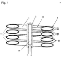
- a process gas 3, to which a coating material 4, such as SiO 2 or Al 2 O 3, is added is activated in a tube 2 by means of a plasma wave 10.
- the tube 2 is arranged in the hollow center of the tube coil 1 in such a way that the resulting plasma stream 11 and the coating material 4 flow essentially radially outwards and between the distances 14 of the individual tube turns 5.
- the coating material 4 is deposited on the surface 6 of the coiled tubing 1 and forms a layer that protects the coiled tubing 1 from a corrosion attack.
- the coating can be at atmospheric pressure or better under a reduced pressure be performed.
- a coil 1 trained heat exchanger 12 in a combustion chamber 7 of a water heater is arranged, coated.
- the open underside 15 of the combustion chamber 7 becomes a chamber 8 completed.
- the process gas 3 and Coating material 4 added and activated by means of the plasma source 10.
- the resulting plasma stream 11 takes the same path as that in the normal operation of the Exhaust gases generated by a burner and flow through the combustion chamber Spaces between the individual turns 5 of the coiled tubing 1 in the radial direction outward. This way is conditioned by a subdivision 13.
- the loaded plasma stream 11 subsequently flows around the subdivision 13 or its periphery 16, flows through the Spaces between the remaining turns 5 and flows via an exhaust gas extractor 9 from.
- the exhaust vent 9 is set up so that 7 atmospheric pressure or Coarse vacuum sets.
- the coating material 4 is deposited on the outside of the windings 5 of the heat exchanger 12 and forms the coating 6.
Landscapes
- Engineering & Computer Science (AREA)
- Chemical & Material Sciences (AREA)
- Physics & Mathematics (AREA)
- Mechanical Engineering (AREA)
- Plasma & Fusion (AREA)
- General Engineering & Computer Science (AREA)
- Thermal Sciences (AREA)
- Metallurgy (AREA)
- Materials Engineering (AREA)
- Organic Chemistry (AREA)
- Chemical Kinetics & Catalysis (AREA)
- General Chemical & Material Sciences (AREA)
- Details Of Fluid Heaters (AREA)
- Paints Or Removers (AREA)
- Laminated Bodies (AREA)
- Application Of Or Painting With Fluid Materials (AREA)
- Other Surface Treatments For Metallic Materials (AREA)
Abstract
Description
Claims (2)
- Verfahren zur Beschichtung eines Wärmetauschers, insbesondere eines Rohrwendel-Wärmetauschers, dadurch gekennzeichnet, daß der Wärmetauscher (12) einem diesen vorzugsweise in Richtung der Abgase durchströmenden mittels einer Plasmaquelle aus einem Prozeßgas erzeugten Plasmastrom ausgesetzt wird, dem vorzugsweise SiO2, Al2O3, Si-Verbindungen, Ti-Verbindungen oder deren Mischungen im flüssigen oder gasförmigen Zustand zugesetzt wird.
- Verfahren nach Anspruch 1, dadurch gekennzeichnet, daß die Beschichtung bei Atmosphärendruck oder unter Grobvakuum durchgeführt wird.
Applications Claiming Priority (6)
| Application Number | Priority Date | Filing Date | Title |
|---|---|---|---|
| DE19923000 | 1999-05-12 | ||
| DE19923000 | 1999-05-12 | ||
| DE19922743 | 1999-05-18 | ||
| DE19922743 | 1999-05-18 | ||
| AT7582000A AT411625B (de) | 2000-04-28 | 2000-04-28 | Verfahren zur beschichtung eines wärmetauschers |
| AT7582000 | 2000-04-28 |
Publications (3)
| Publication Number | Publication Date |
|---|---|
| EP1052308A2 true EP1052308A2 (de) | 2000-11-15 |
| EP1052308A3 EP1052308A3 (de) | 2003-07-02 |
| EP1052308B1 EP1052308B1 (de) | 2010-03-24 |
Family
ID=27151321
Family Applications (1)
| Application Number | Title | Priority Date | Filing Date |
|---|---|---|---|
| EP00109660A Expired - Lifetime EP1052308B1 (de) | 1999-05-12 | 2000-05-06 | Verfahren zur Beschichtung eines Wärmetauschers |
Country Status (5)
| Country | Link |
|---|---|
| EP (1) | EP1052308B1 (de) |
| AT (1) | ATE462024T1 (de) |
| DE (1) | DE50015892D1 (de) |
| DK (1) | DK1052308T3 (de) |
| ES (1) | ES2340135T3 (de) |
Cited By (3)
| Publication number | Priority date | Publication date | Assignee | Title |
|---|---|---|---|---|
| WO2008017382A3 (de) * | 2006-08-07 | 2008-09-25 | Behr Gmbh & Co Kg | Verfahren zum herstellen von bauteilen in einem mediumkreislauf, wie insbesondere eines wärmeübertragers und solche bauteile |
| DE102008050941A1 (de) * | 2008-10-10 | 2010-04-22 | Behr Gmbh & Co. Kg | CVD-Beschichtungsverfahren, Beschichtungsvorrichtung und Bauteil einer Fluidführung |
| CN102946958A (zh) * | 2010-06-22 | 2013-02-27 | I.D.E.技术有限公司 | 具有涂层与波纹管的蒸发器 |
Family Cites Families (4)
| Publication number | Priority date | Publication date | Assignee | Title |
|---|---|---|---|---|
| JPH08232082A (ja) * | 1995-02-27 | 1996-09-10 | Mitsui Eng & Shipbuild Co Ltd | 高温用金属部材 |
| GB2306510B (en) * | 1995-11-02 | 1999-06-23 | Univ Surrey | Modification of metal surfaces |
| JPH09300095A (ja) * | 1996-05-15 | 1997-11-25 | Sumitomo Light Metal Ind Ltd | アルミニウムろう付け用部材 |
| GB9910841D0 (en) * | 1999-05-10 | 1999-07-07 | Univ Nanyang | Heat transfer surface |
-
2000
- 2000-05-06 ES ES00109660T patent/ES2340135T3/es not_active Expired - Lifetime
- 2000-05-06 DK DK00109660.1T patent/DK1052308T3/da active
- 2000-05-06 EP EP00109660A patent/EP1052308B1/de not_active Expired - Lifetime
- 2000-05-06 AT AT00109660T patent/ATE462024T1/de active
- 2000-05-06 DE DE50015892T patent/DE50015892D1/de not_active Expired - Lifetime
Cited By (3)
| Publication number | Priority date | Publication date | Assignee | Title |
|---|---|---|---|---|
| WO2008017382A3 (de) * | 2006-08-07 | 2008-09-25 | Behr Gmbh & Co Kg | Verfahren zum herstellen von bauteilen in einem mediumkreislauf, wie insbesondere eines wärmeübertragers und solche bauteile |
| DE102008050941A1 (de) * | 2008-10-10 | 2010-04-22 | Behr Gmbh & Co. Kg | CVD-Beschichtungsverfahren, Beschichtungsvorrichtung und Bauteil einer Fluidführung |
| CN102946958A (zh) * | 2010-06-22 | 2013-02-27 | I.D.E.技术有限公司 | 具有涂层与波纹管的蒸发器 |
Also Published As
| Publication number | Publication date |
|---|---|
| ATE462024T1 (de) | 2010-04-15 |
| ES2340135T3 (es) | 2010-05-31 |
| EP1052308A3 (de) | 2003-07-02 |
| DK1052308T3 (da) | 2010-06-28 |
| DE50015892D1 (de) | 2010-05-06 |
| EP1052308B1 (de) | 2010-03-24 |
Similar Documents
| Publication | Publication Date | Title |
|---|---|---|
| EP1344013B1 (de) | Kondensationswärmeüberträger | |
| EP0608793A2 (de) | Magnetisch-induktiver Durchflussmesser | |
| WO2008083971A2 (de) | Wärmetauscherrohre und verfahren zur herstellung von wärmeaustauscherrohren | |
| EP1052308B1 (de) | Verfahren zur Beschichtung eines Wärmetauschers | |
| EP0951580B1 (de) | Verfahren zur Herstellung einer Beschichtung | |
| DE10023218A1 (de) | Verfahren zur Beschichtung eines Wärmetauschers | |
| AT411625B (de) | Verfahren zur beschichtung eines wärmetauschers | |
| TW448287B (en) | Heating element for a regenerative heat exchanger, and process for producing a heating element | |
| EP3574054A1 (de) | Verwendung von sio2-beschichtungen in wasserführenden kühlsystemen | |
| DE3911276C1 (en) | Device for recovering (reclaiming) heat from the exhaust gases of firing units (installations, systems) | |
| DE3534724C2 (de) | ||
| DE2720078A1 (de) | Verfahren zur vergroesserung der waermeaustauschenden flaeche von graphitelementen in einem waermeaustauscher | |
| AT405321B (de) | Korrosionsbeständiges verbundrohr, verfahren zu dessen herstellung und dessen verwendung | |
| EP1475597B1 (de) | Heizelement für einen Regenerativ-Wärmetauscher und Verfahren zum Herstellen eines Heizelements | |
| DE3331340A1 (de) | Zentralheizungskessel | |
| DE10144865B4 (de) | Verfahren zum Schutz eines elektrischen Heizkörpers und Heizkörper | |
| DE10359573A1 (de) | Wärmeübertragungseinheit für einen Wärmetauscher | |
| DE102006044201B4 (de) | Nachschaltwärmetauscher für einen Heizkessel | |
| DE10257251A1 (de) | Durchlauferhitzer | |
| EP0711954A2 (de) | Luft/Abgas-Schornstein | |
| JPH02309153A (ja) | 給湯器 | |
| DE69605916T2 (de) | Verfahren zur herstellung eines wärmetauchers | |
| DE2035250B2 (de) | Wärmeabsorbierende Matrix für regenerative Wärmetauscher | |
| JPH0588667B2 (de) | ||
| DE29920530U1 (de) | Wärmetauscher |
Legal Events
| Date | Code | Title | Description |
|---|---|---|---|
| PUAI | Public reference made under article 153(3) epc to a published international application that has entered the european phase |
Free format text: ORIGINAL CODE: 0009012 |
|
| AK | Designated contracting states |
Kind code of ref document: A2 Designated state(s): AT BE CH CY DE DK ES FI FR GB GR IE IT LI LU MC NL PT SE |
|
| AX | Request for extension of the european patent |
Free format text: AL;LT;LV;MK;RO;SI |
|
| RAP1 | Party data changed (applicant data changed or rights of an application transferred) |
Owner name: VAILLANT GMBH |
|
| PUAL | Search report despatched |
Free format text: ORIGINAL CODE: 0009013 |
|
| AK | Designated contracting states |
Designated state(s): AT BE CH CY DE DK ES FI FR GB GR IE IT LI LU MC NL PT SE |
|
| AX | Request for extension of the european patent |
Extension state: AL LT LV MK RO SI |
|
| RIC1 | Information provided on ipc code assigned before grant |
Ipc: 7C 23C 16/00 B Ipc: 7F 28F 19/02 B Ipc: 7C 23C 16/40 A |
|
| 17P | Request for examination filed |
Effective date: 20030701 |
|
| AKX | Designation fees paid |
Designated state(s): AT BE CH CY DE DK ES FI FR GB GR IE IT LI LU MC NL PT SE |
|
| 17Q | First examination report despatched |
Effective date: 20090218 |
|
| GRAP | Despatch of communication of intention to grant a patent |
Free format text: ORIGINAL CODE: EPIDOSNIGR1 |
|
| GRAS | Grant fee paid |
Free format text: ORIGINAL CODE: EPIDOSNIGR3 |
|
| GRAA | (expected) grant |
Free format text: ORIGINAL CODE: 0009210 |
|
| AK | Designated contracting states |
Kind code of ref document: B1 Designated state(s): AT BE CH CY DE DK ES FI FR GB GR IE IT LI LU MC NL PT SE |
|
| REG | Reference to a national code |
Ref country code: GB Ref legal event code: FG4D Free format text: NOT ENGLISH |
|
| REG | Reference to a national code |
Ref country code: CH Ref legal event code: EP |
|
| REG | Reference to a national code |
Ref country code: IE Ref legal event code: FG4D |
|
| REF | Corresponds to: |
Ref document number: 50015892 Country of ref document: DE Date of ref document: 20100506 Kind code of ref document: P |
|
| REG | Reference to a national code |
Ref country code: ES Ref legal event code: FG2A Ref document number: 2340135 Country of ref document: ES Kind code of ref document: T3 |
|
| REG | Reference to a national code |
Ref country code: DK Ref legal event code: T3 |
|
| REG | Reference to a national code |
Ref country code: NL Ref legal event code: T3 |
|
| PG25 | Lapsed in a contracting state [announced via postgrant information from national office to epo] |
Ref country code: FI Free format text: LAPSE BECAUSE OF FAILURE TO SUBMIT A TRANSLATION OF THE DESCRIPTION OR TO PAY THE FEE WITHIN THE PRESCRIBED TIME-LIMIT Effective date: 20100324 |
|
| REG | Reference to a national code |
Ref country code: IE Ref legal event code: FD4D |
|
| PG25 | Lapsed in a contracting state [announced via postgrant information from national office to epo] |
Ref country code: SE Free format text: LAPSE BECAUSE OF FAILURE TO SUBMIT A TRANSLATION OF THE DESCRIPTION OR TO PAY THE FEE WITHIN THE PRESCRIBED TIME-LIMIT Effective date: 20100324 Ref country code: GR Free format text: LAPSE BECAUSE OF FAILURE TO SUBMIT A TRANSLATION OF THE DESCRIPTION OR TO PAY THE FEE WITHIN THE PRESCRIBED TIME-LIMIT Effective date: 20100625 |
|
| PG25 | Lapsed in a contracting state [announced via postgrant information from national office to epo] |
Ref country code: MC Free format text: LAPSE BECAUSE OF NON-PAYMENT OF DUE FEES Effective date: 20100531 |
|
| PLBE | No opposition filed within time limit |
Free format text: ORIGINAL CODE: 0009261 |
|
| STAA | Information on the status of an ep patent application or granted ep patent |
Free format text: STATUS: NO OPPOSITION FILED WITHIN TIME LIMIT |
|
| PG25 | Lapsed in a contracting state [announced via postgrant information from national office to epo] |
Ref country code: PT Free format text: LAPSE BECAUSE OF FAILURE TO SUBMIT A TRANSLATION OF THE DESCRIPTION OR TO PAY THE FEE WITHIN THE PRESCRIBED TIME-LIMIT Effective date: 20100726 Ref country code: IE Free format text: LAPSE BECAUSE OF FAILURE TO SUBMIT A TRANSLATION OF THE DESCRIPTION OR TO PAY THE FEE WITHIN THE PRESCRIBED TIME-LIMIT Effective date: 20100324 |
|
| 26N | No opposition filed |
Effective date: 20101228 |
|
| PG25 | Lapsed in a contracting state [announced via postgrant information from national office to epo] |
Ref country code: CY Free format text: LAPSE BECAUSE OF FAILURE TO SUBMIT A TRANSLATION OF THE DESCRIPTION OR TO PAY THE FEE WITHIN THE PRESCRIBED TIME-LIMIT Effective date: 20100324 |
|
| PG25 | Lapsed in a contracting state [announced via postgrant information from national office to epo] |
Ref country code: LU Free format text: LAPSE BECAUSE OF NON-PAYMENT OF DUE FEES Effective date: 20100506 |
|
| REG | Reference to a national code |
Ref country code: FR Ref legal event code: PLFP Year of fee payment: 16 |
|
| PGFP | Annual fee paid to national office [announced via postgrant information from national office to epo] |
Ref country code: DK Payment date: 20150508 Year of fee payment: 16 Ref country code: GB Payment date: 20150429 Year of fee payment: 16 Ref country code: CH Payment date: 20150508 Year of fee payment: 16 Ref country code: ES Payment date: 20150408 Year of fee payment: 16 |
|
| PGFP | Annual fee paid to national office [announced via postgrant information from national office to epo] |
Ref country code: NL Payment date: 20150429 Year of fee payment: 16 Ref country code: FR Payment date: 20150506 Year of fee payment: 16 Ref country code: BE Payment date: 20150507 Year of fee payment: 16 Ref country code: AT Payment date: 20150506 Year of fee payment: 16 Ref country code: IT Payment date: 20150527 Year of fee payment: 16 |
|
| PG25 | Lapsed in a contracting state [announced via postgrant information from national office to epo] |
Ref country code: BE Free format text: LAPSE BECAUSE OF NON-PAYMENT OF DUE FEES Effective date: 20160531 |
|
| REG | Reference to a national code |
Ref country code: CH Ref legal event code: PL |
|
| REG | Reference to a national code |
Ref country code: DK Ref legal event code: EBP Effective date: 20160531 |
|
| REG | Reference to a national code |
Ref country code: NL Ref legal event code: MM Effective date: 20160601 |
|
| REG | Reference to a national code |
Ref country code: AT Ref legal event code: MM01 Ref document number: 462024 Country of ref document: AT Kind code of ref document: T Effective date: 20160506 |
|
| GBPC | Gb: european patent ceased through non-payment of renewal fee |
Effective date: 20160506 |
|
| PG25 | Lapsed in a contracting state [announced via postgrant information from national office to epo] |
Ref country code: LI Free format text: LAPSE BECAUSE OF NON-PAYMENT OF DUE FEES Effective date: 20160531 Ref country code: CH Free format text: LAPSE BECAUSE OF NON-PAYMENT OF DUE FEES Effective date: 20160531 |
|
| PG25 | Lapsed in a contracting state [announced via postgrant information from national office to epo] |
Ref country code: AT Free format text: LAPSE BECAUSE OF NON-PAYMENT OF DUE FEES Effective date: 20160506 Ref country code: IT Free format text: LAPSE BECAUSE OF NON-PAYMENT OF DUE FEES Effective date: 20160506 Ref country code: NL Free format text: LAPSE BECAUSE OF NON-PAYMENT OF DUE FEES Effective date: 20160601 |
|
| REG | Reference to a national code |
Ref country code: FR Ref legal event code: ST Effective date: 20170131 |
|
| PG25 | Lapsed in a contracting state [announced via postgrant information from national office to epo] |
Ref country code: FR Free format text: LAPSE BECAUSE OF NON-PAYMENT OF DUE FEES Effective date: 20160531 |
|
| PG25 | Lapsed in a contracting state [announced via postgrant information from national office to epo] |
Ref country code: GB Free format text: LAPSE BECAUSE OF NON-PAYMENT OF DUE FEES Effective date: 20160506 Ref country code: DK Free format text: LAPSE BECAUSE OF NON-PAYMENT OF DUE FEES Effective date: 20160531 |
|
| REG | Reference to a national code |
Ref country code: ES Ref legal event code: FD2A Effective date: 20180507 |
|
| PG25 | Lapsed in a contracting state [announced via postgrant information from national office to epo] |
Ref country code: ES Free format text: LAPSE BECAUSE OF NON-PAYMENT OF DUE FEES Effective date: 20160507 |
|
| PGFP | Annual fee paid to national office [announced via postgrant information from national office to epo] |
Ref country code: DE Payment date: 20190506 Year of fee payment: 20 |