EP1052184A2 - Reusable display package for circular blade or other display item - Google Patents
Reusable display package for circular blade or other display item Download PDFInfo
- Publication number
- EP1052184A2 EP1052184A2 EP00303692A EP00303692A EP1052184A2 EP 1052184 A2 EP1052184 A2 EP 1052184A2 EP 00303692 A EP00303692 A EP 00303692A EP 00303692 A EP00303692 A EP 00303692A EP 1052184 A2 EP1052184 A2 EP 1052184A2
- Authority
- EP
- European Patent Office
- Prior art keywords
- portions
- body portions
- display item
- rear body
- closed position
- Prior art date
- Legal status (The legal status is an assumption and is not a legal conclusion. Google has not performed a legal analysis and makes no representation as to the accuracy of the status listed.)
- Granted
Links
Images


Classifications
-
- B—PERFORMING OPERATIONS; TRANSPORTING
- B65—CONVEYING; PACKING; STORING; HANDLING THIN OR FILAMENTARY MATERIAL
- B65D—CONTAINERS FOR STORAGE OR TRANSPORT OF ARTICLES OR MATERIALS, e.g. BAGS, BARRELS, BOTTLES, BOXES, CANS, CARTONS, CRATES, DRUMS, JARS, TANKS, HOPPERS, FORWARDING CONTAINERS; ACCESSORIES, CLOSURES, OR FITTINGS THEREFOR; PACKAGING ELEMENTS; PACKAGES
- B65D73/00—Packages comprising articles attached to cards, sheets or webs
- B65D73/0064—Packages comprising articles attached to cards, sheets or webs the articles being supported by or suspended from a tag-like element
- B65D73/0071—Packages comprising articles attached to cards, sheets or webs the articles being supported by or suspended from a tag-like element the tag-like element being doubled-over to engage the upper part of the article
-
- B—PERFORMING OPERATIONS; TRANSPORTING
- B65—CONVEYING; PACKING; STORING; HANDLING THIN OR FILAMENTARY MATERIAL
- B65D—CONTAINERS FOR STORAGE OR TRANSPORT OF ARTICLES OR MATERIALS, e.g. BAGS, BARRELS, BOTTLES, BOXES, CANS, CARTONS, CRATES, DRUMS, JARS, TANKS, HOPPERS, FORWARDING CONTAINERS; ACCESSORIES, CLOSURES, OR FITTINGS THEREFOR; PACKAGING ELEMENTS; PACKAGES
- B65D85/00—Containers, packaging elements or packages, specially adapted for particular articles or materials
- B65D85/58—Containers, packaging elements or packages, specially adapted for particular articles or materials for ball bearings, washers, buttons or like spherical or disc-shaped articles
-
- Y—GENERAL TAGGING OF NEW TECHNOLOGICAL DEVELOPMENTS; GENERAL TAGGING OF CROSS-SECTIONAL TECHNOLOGIES SPANNING OVER SEVERAL SECTIONS OF THE IPC; TECHNICAL SUBJECTS COVERED BY FORMER USPC CROSS-REFERENCE ART COLLECTIONS [XRACs] AND DIGESTS
- Y02—TECHNOLOGIES OR APPLICATIONS FOR MITIGATION OR ADAPTATION AGAINST CLIMATE CHANGE
- Y02W—CLIMATE CHANGE MITIGATION TECHNOLOGIES RELATED TO WASTEWATER TREATMENT OR WASTE MANAGEMENT
- Y02W30/00—Technologies for solid waste management
- Y02W30/50—Reuse, recycling or recovery technologies
- Y02W30/80—Packaging reuse or recycling, e.g. of multilayer packaging
Definitions
- the invention relates generally to display packages for circular cutting blades, similar disk-like products, or other display items. More particularly, the invention relates to such packages that are intended to be reused for storing or holding the blade or other item after being initially opened by the user.
- Such previous packages include skin packs, blister packs, shrink-wrapped and card-mounted packages, as well as other similar arrangements. These packages have frequently been found to be difficult to open without destroying or severely damaging the packaging, thus rendering the package unusable for post-opening storage or carrying by the user. Such packages have also been expensive and wasteful and have often been composed of materials that are difficult or impossible to recycle. In addition, many of such previous packages have inhibited the viewer's ability to easily see, feel and evaluate the product being displayed. Furthermore, such prior packages have usually been dedicated packages usable with only one display item, thus requiring different display packages for each of a number of different display items, even though such display items are very similar to one another.
- a reusable package for displaying, holding and/or storing a display item, such as a circular cutting blade, for example, where the display item has a central aperture therethrough and at least one surface discontinuity thereon.
- the preferred reusable package includes front and rear body portions hingedly interconnected with each other in order to be selectively foldable between a fully closed generally face-to-face position and a fully open separated position.
- the preferred package includes complementary closure portions formed in the front and rear body portions, with the closure portions being mutually engageable in a gripping and releasable relationship within and through the central aperture of the display item when the front and rear body portions are folded to their closed position.
- At least one of the front or rear body portions includes an anti-rotation lug protruding inwardly therefrom to be engageable with the surface discontinuity on the display item, such as a space between adjacent teeth on a cutting blade, for example, thus substantially preventing the display item from rotating about its central aperture when the package is closed.
- the other body portion includes a second anti-rotation lug located at a different location relative to the closure portions so that the package can be used to display, hold and store at least two different, but similar display items.
- the front and rear body portions each include a header portion and a depending triangular support portion with the respective front and rear header portions and the respective front and rear triangular support portions being generally complementary in size and shape to each other and being mutually engageable with each other when the body portions are in the closed position.
- the front and rear header portions include respective dished or recessed "clam-shell” portions releasably and nestably engageable with each other when the package is in its closed position.
- the rear header portion also includes a second rear dished portion formed therein but opening generally forwardly (opposite that of the front dished portion) when the front and rear body portions are in the closed position, with the second rear dished portion being generally surrounded by the first rear dished portion. Since the second rear dished portion has its open side facing toward the open side of the front dished portion, they form a shallow cavity therebetween, in which display cards, anti-theft security devices, or small accessories, for example, may be housed or stored.
- the closure portions include a closure post on one of the front or rear body portions and the closure recess on the other of the front or rear body portions with the post and recess being grippingly and releasably engageable with each other through the display item's central aperture when the package is in its closed position, thus allowing the user to repeatedly open and close the package after initially opening it.
- the front and rear body portions are initially attached to each other (such as by ultrasonic welding for example) to secure them in their closed position with the display item disclosed therebetween. This initial attachment is frangible and easily broken by the user in order to allow the front and rear body portions to be unfolded from each other for initial removal of the display item.
- closure portions are grippingly and releasably nestable with each other, within and through the central aperture of the display item, in order to allow the front and rear body portions to be repeatedly and releasably secured in their closed position after the frangible initial attachment has been broken.
- At least one hang-hole is provided through each of the front and rear body portions, with the hang-holes being aligned with each other when the package is in its closed position in order to allow the package to be hung on a peg, hook, nail, or other external protruding member.
- hang-holes and preferably the closure post and recess, are reinforced by surrounding bosses.
- FIGS 1 through 7 illustrate and depict one exemplary preferred embodiment according to the present invention, wherein a display package 10 is adapted for holding, storing and displaying a cutting blade 12 (or a different cutting blade 12a) is illustrated.
- a display package 10 is adapted for holding, storing and displaying a cutting blade 12 (or a different cutting blade 12a) is illustrated.
- a cutting blade 12 or a different cutting blade 12a
- FIG. 1 illustrate and depict one exemplary preferred embodiment according to the present invention, wherein a display package 10 is adapted for holding, storing and displaying a cutting blade 12 (or a different cutting blade 12a) is illustrated.
- a cutting blade 12 or a different cutting blade 12a
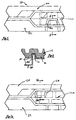
- the reusable display package 10 is shown for displaying, holding and storing a cutting blade 12 having a number of cutting teeth 14 spaced about its radial periphery with spaces 16 lying between adjacent pairs of cutting teeth 14.
- the reusable display package 10 includes a front body portion 20 and a rear body portion 22 foldably interconnected by a living hinge 24 to allow the front and rear body portions 20 and 22 to be foldably opened and closed between the closed position shown in Figures 1, 2 and 4 and the open position shown in Figure 3.
- both of the front and rear body portions 20 and 22 are substantially transparent.
- a closure post 26 is formed in the front body portion 20, with a complementary closure recess 28 being formed in the rear body portion 22 (also seen in Figure 7).
- a reinforcing boss 29 surrounds the closure post 26, and a similar reinforcing boss 30 surrounds the closure recess 28, in order to enhance the durability of the display package 10.
- the closure post 26 and the closure recess 28 may alternatively be formed in the rear body portion 22 and the front body portion 20, respectively, rather than as shown in the drawings.
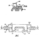
- the front body portion 20 preferably includes a generally rectangular front header portion 32 and a depending front triangular portion 36.
- the rear body portion 22 preferably includes a generally rectangular rear header portion 34 and a depending rear triangular portion 38.
- the front header portion 32 has a front dished portion formed therein, and the rear header portion 34 has a similar first larger rear dished portion 42 formed therein, with the dished portions 40 and 42 both facing in the same direction when the display package 10 is in its closed position in order to releasably nest within each other.
- a second smaller rear dished portion 44 is formed within the first rear dished portion 42 of the rear header portion 34, with the second rear dished portion opening in an opposite direction from that of the front dished portion when the display package 10 is in its closed position, thereby forming a cavity 46 therebetween.
- One or more insert cards such as the first insert card 48 and the second insert card 50, shown in Figure 3, can be housed within the cavity 46 and can include information about the cutting blade 12 or other display item printed thereon.
- the cavity 46 can also house a magnetic or other similar anti-theft security device 52, which can be concealed between the first and second insert cards 48 and 50. Arbor inserts 54 or other such accessories can also be housed within the cavity 46.
- a first anti-rotation lug 56 is formed on the rear triangular portion 38 and is engageable with a surface discontinuity, such as the tooth space 16 between adjacent teeth 14 of the cutting blade 12, as is shown in Figures 5 and 6. This retains the cutting blade 12 or other display item in an orientation such that any information printed thereon is properly oriented, for example.
- a second anti-rotation lug 58 is formed on the rear triangular portion 36 and is located at a location farther from the closure post 26 and the closure recess 28 than that of the first anti-rotation lug 56. This allows the display package 10 to be used with at least two different cutting blades 12 and 12a.
- These first and second anti-rotation lugs 56 and 58 can, of course, alternately be formed on the front and rear triangular portions 36 and 38, respectively, rather than as shown in the drawings.
- the front and rear triangular portions 36 and 38 are preferably sized to allow at least one-half, and preferably approximately two-thirds, of the cutting blade 12 to be exposed and open to clear inspection, touch and evaluation by a viewer.
- the front triangular portions 36 and 38 preferably include respective stiffening ribs 68 and 70 to minimize the tendency of the triangular portions 36 and 38 to unduly flex or bend and further to enhance the durability of the display package 10.
- the front and rear body portions 20 and 22 include hang-holes 64 that are aligned with each other when the display package 10 is in its closed position, thus allowing the display package 10 to be hung on a peg, nail, hook or other external protruding member for display purposes in a commercial establishment as well as for storage and blade identification purposes by the user in his or her own facility.
- the hang-holes 64 are preferably surrounded by hang-hole reinforcing bosses 66 in order to further enhance the strength and durability of the display package 10.
- the front and rear body portions 20 and 22 are initially secured to each other by frangible attachments 60, which can be ultrasonic welds or other such well-known attachments. These attachments 60, or the material around them, are designed to be easily broken by the user without destroying or unduly damaging the package 10. Thereafter, the display package 10 is reusable and repeatedly reclosable and reopenable as described above.
- frangible attachments 60 can be ultrasonic welds or other such well-known attachments.
Landscapes
- Engineering & Computer Science (AREA)
- Mechanical Engineering (AREA)
- Packages (AREA)
Abstract
Description
Claims (16)
- A reusable package for displaying, holding and storing a display item, the display item having a central aperture therethrough and at least one surface discontinuity thereon, said package including a front body portion and a rear body portion each of which having inner and outer sides and being hingedly interconnected with each other in order to be selectively foldable relative to each other between a fully closed position with their respective inner sides in a generally face-to-face abutting relationship and a fully open position with their respective inner sides being separated and generally coplanar, at least said front body portion being at least partially transparent in order to allow a viewer to see the display item therethrough, said front and rear body portions having complementary closure portions formed therein, said closure portions being mutually engageable in a gripping and releasable relationship with each other within and through the central aperture of the display item when said front and rear body portions are folded to said closed position with the display item disposed therebetween in order to releasably secure said front and rear body portions in said closed position, at least one of said front and rear body portions having an anti-rotation lug protruding therefrom and being engageable with the surface discontinuity on the display item in order to substantially prevent the display item from rotating about its central aperture when said front and rear body portions are in said closed position with the display item disposed therebetween.
- A reusable package according to claim 1, wherein the display item is generally circular and disk-like, the surface discontinuity being on at least one side thereof at a location generally adjacent an outer periphery thereof.
- A reusable package according to either of the preceding claims, wherein the display item is a circular cutting blade, the surface discontinuity being formed by a circumferential space between two adjacent teeth of said cutting blade.
- A reusable package according to any one of the preceding claims, wherein said front and rear body portions each include a header portion and a generally triangular support portion, said respective front and rear header portions being generally complementary in size and shape and being mutually engageable with each other when said body portions are in said closed position, said front and rear header portions including respective dished portions releasably nestable with each other when said front and rear body portions are in said closed position, and said respective front and rear support portions being generally complementary in size and shape and mutually engageable with each other when said body portions are in said closed position, said closure portions including a closure post on one of said support portions and a complementary closure recess on the other of said support portions, said closure post and said closure recess being grippingly and releasably nestable with each other in order to releasably secure said front and rear body portions in said closed position, said front and rear triangular support portions each further including stiffening ribs formed therein and extending along respective sides thereof from a location generally adjacent said respective header portions to a location generally adjacent the respective apexes of said triangular support portions.
- A reusable package according to claim 4, wherein said closure post and said closure recess are located generally adjacent said respective apexes of said respective support portions.
- A reusable package according to either claim 4 or claim 5, wherein said front and rear support portions cover less than one-half of the display item when said front and rear body portions are in said closed position with said display item held therebetween.
- A reusable package according to any one of claims 4 to 6, wherein said front and rear support portions cover approximately one-third of the display item when said front and rear body portions are in said closed position with said display item held therebetween.
- A reusable package according to any one of claims 4 to 7, wherein said rear header portion also includes a second rear dished portion formed therein and opening generally forwardly when said front and rear body portions are in said closed position, said second rear dished portion and said front dished portion forming a cavity therebetween.
- A reusable package according to claim 8, further including an insert card and an anti-theft security member removably disposed within said cavity when said front and rear body portions are in said closed position.
- A reusable package according to claim 9, further including a second insert card removably disposed within said cavity when said front and rear body portions are in said closed position, said security member being concealed from view between said insert cards.
- A reusable package according to any one of claims 8 to 10, wherein said insert card has product information about the display item printed thereon.
- A reusable package according to any one of the preceding claims, wherein said front and rear body portions are initially attached to each other to secure them in said closed position with the display item disposed therebetween, said attachment being frangible in order to allow said front and rear body portions to be unfolded from each other for selective removal of the display item, said closure portions being grippingly and releasably nestable with each other in order to releasably secure said front and rear body portions in said closed position after said frangible attachment has been broken.
- A reusable package according to any one of the preceding claims, further including at least one hang-hole extending through each of said front and rear body portions, said hang-holes being aligned with each other when said front and rear body portions are in said closed position in order to allow said package to be hung on an external protruding member.
- A reusable package according to claim 13, wherein each of said hang-holes is surrounded by a reinforcing boss formed in the respective body portion.
- A reusable package according to any one of the preceding claims, wherein the other of said front and rear body portions has a second anti-rotation lug protruding therefrom, said second anti-rotation lug being located at a position relative to said closure portions that is different from the position of said first anti-rotation lug relative to said closure portions in order to be engageable with a surface discontinuity on a different display item, thereby allowing said package to be used with at least two different display items.
- A reusable package according to claim 15, wherein said second anti-rotation lug is located at a position farther away from said closure portions than said first anti-rotation lug in order to allow said package to be used interchangeably with display items having different diameters.
Applications Claiming Priority (2)
| Application Number | Priority Date | Filing Date | Title |
|---|---|---|---|
| US304028 | 1999-05-03 | ||
| US09/304,028 US6161693A (en) | 1999-05-03 | 1999-05-03 | Reusable display package for circular blade or other display item |
Publications (3)
| Publication Number | Publication Date |
|---|---|
| EP1052184A2 true EP1052184A2 (en) | 2000-11-15 |
| EP1052184A3 EP1052184A3 (en) | 2001-05-02 |
| EP1052184B1 EP1052184B1 (en) | 2003-11-05 |
Family
ID=23174724
Family Applications (1)
| Application Number | Title | Priority Date | Filing Date |
|---|---|---|---|
| EP20000303692 Expired - Lifetime EP1052184B1 (en) | 1999-05-03 | 2000-05-03 | Reusable display package for circular blade or other display item |
Country Status (4)
| Country | Link |
|---|---|
| US (1) | US6161693A (en) |
| EP (1) | EP1052184B1 (en) |
| AT (1) | ATE253508T1 (en) |
| DE (1) | DE60006312T2 (en) |
Cited By (4)
| Publication number | Priority date | Publication date | Assignee | Title |
|---|---|---|---|---|
| DE20219617U1 (en) * | 2002-12-17 | 2004-04-29 | Diewe Diamantwerkzeuge Gmbh | Package for cutter wheels is made by folding one-piece blank and has front section which is smaller than wheel, which is held in place by raised ring on back section and tabs on front section |
| EP1489022A2 (en) * | 2003-06-17 | 2004-12-22 | Olympia Group, Inc. | Tool securing mechanism for hangtag assembly |
| US7121031B2 (en) | 2003-06-10 | 2006-10-17 | Olympia Group, Inc. | Hangtag with tool securing mechanism |
| EP4069458A4 (en) * | 2019-12-05 | 2024-01-17 | Milwaukee Electric Tool Corporation | Circular saw blade holder |
Families Citing this family (11)
| Publication number | Priority date | Publication date | Assignee | Title |
|---|---|---|---|---|
| US6640969B2 (en) | 2001-09-05 | 2003-11-04 | David A. Darby | Decorative disc holder |
| US7445120B2 (en) * | 2004-05-12 | 2008-11-04 | Cequent Consumer Products | Folding reusable display and article storage package |
| DE202004009963U1 (en) * | 2004-06-24 | 2005-10-27 | Rti Sports Vertrieb Von Sportartikeln Gmbh | Display for bicycle grips |
| US20080016730A1 (en) * | 2006-07-19 | 2008-01-24 | Pc/Nametag, Inc. | Clamshell badge/nametag holder |
| GB2473804A (en) * | 2008-07-17 | 2011-03-30 | Black & Decker Inc | Circular saw blade display package with removable locking device |
| US8267245B2 (en) * | 2009-09-02 | 2012-09-18 | Black & Decker Inc. | Method and package for displaying magnetic tool container |
| US8746451B2 (en) * | 2011-04-28 | 2014-06-10 | Robert Bosch Gmbh | Circular saw blade protector |
| US8443972B1 (en) | 2011-12-23 | 2013-05-21 | Robert Bosch Gmbh | Hang tag assembly for a hole saw |
| US8800768B2 (en) | 2012-05-31 | 2014-08-12 | Milwaukee Electric Tool Corporation | Clamshell packaging |
| US11299322B2 (en) * | 2019-10-08 | 2022-04-12 | John Lee | Stackable sawblade containment assembly |
| WO2021142832A1 (en) * | 2020-01-19 | 2021-07-22 | Logitech Europe S.A. | Eco-friendly hang tabs |
Citations (2)
| Publication number | Priority date | Publication date | Assignee | Title |
|---|---|---|---|---|
| US2459460A (en) * | 1947-09-20 | 1949-01-18 | Arthur R Segal | Case for circle saws |
| US5713463A (en) * | 1996-08-15 | 1998-02-03 | 30G, Inc. | Folding data disk holder |
Family Cites Families (46)
| Publication number | Priority date | Publication date | Assignee | Title |
|---|---|---|---|---|
| US1585846A (en) * | 1921-11-14 | 1926-05-25 | Mid West Box Company | Mailing holder for phonograph records |
| US1500136A (en) * | 1923-08-01 | 1924-07-08 | Weyerhaeuser Forest Products | Crate |
| DE820419C (en) * | 1950-02-02 | 1951-11-08 | Fritz Werner A G | Packaging for bodies of any shape |
| US2950004A (en) * | 1957-11-14 | 1960-08-23 | Frederick G Acomb | Merchandising display package |
| US3053424A (en) * | 1960-08-04 | 1962-09-11 | Cheyenne A Reinhard | Carrier for circular saw blades |
| US3109539A (en) * | 1960-11-17 | 1963-11-05 | Walfredo Toscanni | Record album |
| US3259231A (en) * | 1964-08-17 | 1966-07-05 | Black & Decker Mfg Co | Package for article of manufacture |
| US3534358A (en) * | 1966-10-20 | 1970-10-13 | Logistics Ind Corp | Apparatus for detecting objects |
| US3596822A (en) * | 1969-05-21 | 1971-08-03 | Holley Plastics Co | Package structure |
| US3776375A (en) * | 1972-01-25 | 1973-12-04 | Packaging Ind Inc | Free-standing blister package |
| US3825112A (en) * | 1972-10-30 | 1974-07-23 | Crested Butte Records Inc | Record cover |
| FR2238211B1 (en) * | 1973-07-19 | 1976-09-17 | Paudras Francis | |
| US3899100A (en) * | 1973-07-20 | 1975-08-12 | Tiros Plastics Corp | Container for packaging an object |
| US4005776A (en) * | 1975-05-02 | 1977-02-01 | Plastofilm Industries, Inc. | Package for oral thermometer, catheter or the like |
| US4020694A (en) * | 1975-11-26 | 1977-05-03 | Hopkins Manufacturing Corporation | Apparatus for displaying and manipulating an indoor/outdoor thermometer |
| GB1575521A (en) * | 1976-08-09 | 1980-09-24 | Rca Corp | Record disc package having a centre post |
| US4324331A (en) * | 1980-08-08 | 1982-04-13 | Zimmer, Inc. | Packaging for surgical implements |
| US4327512A (en) * | 1980-12-11 | 1982-05-04 | Oliver Robert L | Identification device |
| US4619364A (en) * | 1982-09-13 | 1986-10-28 | The Stanley Works | Display package for drill bits and the like |
| US4499353A (en) * | 1983-03-03 | 1985-02-12 | Usm Corporation | Blister package |
| US4449629A (en) * | 1983-03-29 | 1984-05-22 | The Stanley Works | Display and storage container for multiple tool parts and the like |
| US4588082A (en) * | 1985-03-19 | 1986-05-13 | Plastic Oddities, Inc. | Circular sawblade packaging case |
| US4687129A (en) * | 1985-09-06 | 1987-08-18 | Vsi Fasteners, Inc. | Reusable container |
| US4681223A (en) * | 1986-02-04 | 1987-07-21 | The Stanley Works | Knife blade package and container therefor |
| US4702373A (en) * | 1986-02-24 | 1987-10-27 | Meade Dan G | Hub cover interacting with reel of magnetic tape for forming document storage compartment |
| FR2620919B2 (en) * | 1987-06-24 | 1990-04-06 | Matuz Louis | LOCKING DEVICE FOR A COMPACT DISC SALE OR LOAN BOX |
| US4895252A (en) * | 1987-12-18 | 1990-01-23 | Laservideo, Inc. | Optical disc package |
| US4903829A (en) * | 1988-10-07 | 1990-02-27 | Clemens Philip M | Container for compact disc |
| US4921096A (en) * | 1989-01-17 | 1990-05-01 | Taut, Inc. | Package assembly |
| US4872551A (en) * | 1989-03-08 | 1989-10-10 | Klein Tools Corporation | Working clamshell blister package for pliers or similar hand tools |
| US5133454A (en) * | 1990-12-06 | 1992-07-28 | Hammer Steven G | Intravenous catheter biohazard prevention packaging device |
| US5078266A (en) * | 1991-03-12 | 1992-01-07 | Rackley Jimmy W | Rotary saw blade housing apparatus |
| US5293993A (en) * | 1991-06-14 | 1994-03-15 | Dynamic Bio-Apparatuses, Inc. | Syringe sealing container |
| US5238107A (en) * | 1992-01-07 | 1993-08-24 | Kownacki Charles D | Disc storage container having a securing means central aperture |
| US5209354A (en) * | 1992-02-11 | 1993-05-11 | Newell Operating Company | Reusable blister package |
| GB9204773D0 (en) * | 1992-03-05 | 1992-04-15 | Black & Decker Inc | Packaging |
| US5322162A (en) * | 1993-06-22 | 1994-06-21 | Outer Circle Products, Ltd. | Compact CD case |
| US5540324A (en) * | 1993-10-14 | 1996-07-30 | Sterling Inc. | Jewelry package |
| US5456057A (en) * | 1994-03-18 | 1995-10-10 | Black & Decker Inc. | Display package for circular saw blade or similar article, and method |
| US5653335A (en) * | 1995-01-17 | 1997-08-05 | Rand Mcnally Media Services, Inc. | Multi-use package for compact disks and/or diskettes |
| US5595295A (en) * | 1995-09-18 | 1997-01-21 | Lin; C. S. | Device for keeping and displaying a shearing tool |
| US5586657A (en) * | 1995-12-22 | 1996-12-24 | Rayovac Corporation | Security blister package |
| US5871100A (en) * | 1995-12-22 | 1999-02-16 | Rayovac Corporation | Security battery package |
| US5601188A (en) * | 1996-04-18 | 1997-02-11 | Emplast, Inc. | Security package with internal pocket for a surveillance tag |
| US5878886A (en) * | 1996-09-20 | 1999-03-09 | Marshall; John C. | Display package for pull chains and the like |
| US5803253A (en) * | 1997-07-15 | 1998-09-08 | Olympia Industrial Inc. | Tool display device |
-
1999
- 1999-05-03 US US09/304,028 patent/US6161693A/en not_active Expired - Lifetime
-
2000
- 2000-05-03 AT AT00303692T patent/ATE253508T1/en not_active IP Right Cessation
- 2000-05-03 DE DE2000606312 patent/DE60006312T2/en not_active Expired - Fee Related
- 2000-05-03 EP EP20000303692 patent/EP1052184B1/en not_active Expired - Lifetime
Patent Citations (2)
| Publication number | Priority date | Publication date | Assignee | Title |
|---|---|---|---|---|
| US2459460A (en) * | 1947-09-20 | 1949-01-18 | Arthur R Segal | Case for circle saws |
| US5713463A (en) * | 1996-08-15 | 1998-02-03 | 30G, Inc. | Folding data disk holder |
Cited By (6)
| Publication number | Priority date | Publication date | Assignee | Title |
|---|---|---|---|---|
| DE20219617U1 (en) * | 2002-12-17 | 2004-04-29 | Diewe Diamantwerkzeuge Gmbh | Package for cutter wheels is made by folding one-piece blank and has front section which is smaller than wheel, which is held in place by raised ring on back section and tabs on front section |
| US7121031B2 (en) | 2003-06-10 | 2006-10-17 | Olympia Group, Inc. | Hangtag with tool securing mechanism |
| EP1489022A2 (en) * | 2003-06-17 | 2004-12-22 | Olympia Group, Inc. | Tool securing mechanism for hangtag assembly |
| EP1489022A3 (en) * | 2003-06-17 | 2005-01-19 | Olympia Group, Inc. | Tool securing mechanism for hangtag assembly |
| US7210663B2 (en) | 2003-06-17 | 2007-05-01 | Jpj Investment Holding Corporation | Tool securing mechanism for hangtag assembly |
| EP4069458A4 (en) * | 2019-12-05 | 2024-01-17 | Milwaukee Electric Tool Corporation | Circular saw blade holder |
Also Published As
| Publication number | Publication date |
|---|---|
| EP1052184A3 (en) | 2001-05-02 |
| EP1052184B1 (en) | 2003-11-05 |
| DE60006312T2 (en) | 2004-05-13 |
| DE60006312D1 (en) | 2003-12-11 |
| US6161693A (en) | 2000-12-19 |
| ATE253508T1 (en) | 2003-11-15 |
Similar Documents
| Publication | Publication Date | Title |
|---|---|---|
| EP1052184B1 (en) | Reusable display package for circular blade or other display item | |
| US6152299A (en) | Reusable display package for shanked tool or other display item | |
| US6206189B1 (en) | Display container having secure closure mechanism | |
| US6308832B1 (en) | Product display package | |
| US6736267B2 (en) | Display card having reinforced hanger hole | |
| US6364115B1 (en) | Battery package with rotation prevention | |
| US20060249522A1 (en) | Reusable container for retail display of electric cable components | |
| US20070186597A1 (en) | Zipper tag housing | |
| US6398026B1 (en) | Protective package | |
| US5291996A (en) | Reusable display sheath with frangible latch means | |
| WO2002038470A1 (en) | Battery display package | |
| US5579288A (en) | Wristwatch display package | |
| JP2005209516A (en) | Battery containing case | |
| US6401921B1 (en) | Tape measure display container and tape measure | |
| US7445120B2 (en) | Folding reusable display and article storage package | |
| JP3983791B1 (en) | Blister container | |
| EP3087012B1 (en) | Hang tag package for a saw blade | |
| EP2246507A1 (en) | Universal retail security package with cover window | |
| JP6856982B2 (en) | Packaging box | |
| WO2001098171A2 (en) | Battery package with rotation prevention | |
| JP4300304B2 (en) | Tape measure display container and tape measure | |
| JP6972516B2 (en) | Work accessory case | |
| US20020170218A1 (en) | Display card having reinforced hanger hole | |
| JP2007320567A (en) | Packaging body | |
| JP2006223438A (en) | Outer packaging case for displaying cutting tool |
Legal Events
| Date | Code | Title | Description |
|---|---|---|---|
| PUAI | Public reference made under article 153(3) epc to a published international application that has entered the european phase |
Free format text: ORIGINAL CODE: 0009012 |
|
| AK | Designated contracting states |
Kind code of ref document: A2 Designated state(s): AT BE CH CY DE DK ES FI FR GB GR IE IT LI LU MC NL PT SE |
|
| AX | Request for extension of the european patent |
Free format text: AL;LT;LV;MK;RO;SI |
|
| PUAL | Search report despatched |
Free format text: ORIGINAL CODE: 0009013 |
|
| AK | Designated contracting states |
Kind code of ref document: A3 Designated state(s): AT BE CH CY DE DK ES FI FR GB GR IE IT LI LU MC NL PT SE |
|
| AX | Request for extension of the european patent |
Free format text: AL;LT;LV;MK;RO;SI |
|
| 17P | Request for examination filed |
Effective date: 20010524 |
|
| AKX | Designation fees paid |
Free format text: AT BE CH CY DE DK ES FI FR GB GR IE IT LI LU MC NL PT SE |
|
| 17Q | First examination report despatched |
Effective date: 20020306 |
|
| GRAH | Despatch of communication of intention to grant a patent |
Free format text: ORIGINAL CODE: EPIDOS IGRA |
|
| GRAH | Despatch of communication of intention to grant a patent |
Free format text: ORIGINAL CODE: EPIDOS IGRA |
|
| GRAA | (expected) grant |
Free format text: ORIGINAL CODE: 0009210 |
|
| AK | Designated contracting states |
Kind code of ref document: B1 Designated state(s): AT BE CH CY DE DK ES FI FR GB GR IE IT LI LU MC NL PT SE |
|
| PG25 | Lapsed in a contracting state [announced via postgrant information from national office to epo] |
Ref country code: IT Free format text: LAPSE BECAUSE OF FAILURE TO SUBMIT A TRANSLATION OF THE DESCRIPTION OR TO PAY THE FEE WITHIN THE PRESCRIBED TIME-LIMIT;WARNING: LAPSES OF ITALIAN PATENTS WITH EFFECTIVE DATE BEFORE 2007 MAY HAVE OCCURRED AT ANY TIME BEFORE 2007. THE CORRECT EFFECTIVE DATE MAY BE DIFFERENT FROM THE ONE RECORDED. Effective date: 20031105 Ref country code: CY Free format text: LAPSE BECAUSE OF FAILURE TO SUBMIT A TRANSLATION OF THE DESCRIPTION OR TO PAY THE FEE WITHIN THE PRESCRIBED TIME-LIMIT Effective date: 20031105 Ref country code: AT Free format text: LAPSE BECAUSE OF FAILURE TO SUBMIT A TRANSLATION OF THE DESCRIPTION OR TO PAY THE FEE WITHIN THE PRESCRIBED TIME-LIMIT Effective date: 20031105 Ref country code: CH Free format text: LAPSE BECAUSE OF FAILURE TO SUBMIT A TRANSLATION OF THE DESCRIPTION OR TO PAY THE FEE WITHIN THE PRESCRIBED TIME-LIMIT Effective date: 20031105 Ref country code: FR Free format text: LAPSE BECAUSE OF FAILURE TO SUBMIT A TRANSLATION OF THE DESCRIPTION OR TO PAY THE FEE WITHIN THE PRESCRIBED TIME-LIMIT Effective date: 20031105 Ref country code: BE Free format text: LAPSE BECAUSE OF FAILURE TO SUBMIT A TRANSLATION OF THE DESCRIPTION OR TO PAY THE FEE WITHIN THE PRESCRIBED TIME-LIMIT Effective date: 20031105 Ref country code: LI Free format text: LAPSE BECAUSE OF FAILURE TO SUBMIT A TRANSLATION OF THE DESCRIPTION OR TO PAY THE FEE WITHIN THE PRESCRIBED TIME-LIMIT Effective date: 20031105 Ref country code: FI Free format text: LAPSE BECAUSE OF FAILURE TO SUBMIT A TRANSLATION OF THE DESCRIPTION OR TO PAY THE FEE WITHIN THE PRESCRIBED TIME-LIMIT Effective date: 20031105 Ref country code: NL Free format text: LAPSE BECAUSE OF FAILURE TO SUBMIT A TRANSLATION OF THE DESCRIPTION OR TO PAY THE FEE WITHIN THE PRESCRIBED TIME-LIMIT Effective date: 20031105 |
|
| REG | Reference to a national code |
Ref country code: GB Ref legal event code: FG4D |
|
| REG | Reference to a national code |
Ref country code: CH Ref legal event code: EP |
|
| REF | Corresponds to: |
Ref document number: 60006312 Country of ref document: DE Date of ref document: 20031211 Kind code of ref document: P |
|
| REG | Reference to a national code |
Ref country code: IE Ref legal event code: FG4D |
|
| PG25 | Lapsed in a contracting state [announced via postgrant information from national office to epo] |
Ref country code: DK Free format text: LAPSE BECAUSE OF FAILURE TO SUBMIT A TRANSLATION OF THE DESCRIPTION OR TO PAY THE FEE WITHIN THE PRESCRIBED TIME-LIMIT Effective date: 20040205 Ref country code: SE Free format text: LAPSE BECAUSE OF FAILURE TO SUBMIT A TRANSLATION OF THE DESCRIPTION OR TO PAY THE FEE WITHIN THE PRESCRIBED TIME-LIMIT Effective date: 20040205 Ref country code: GR Free format text: LAPSE BECAUSE OF FAILURE TO SUBMIT A TRANSLATION OF THE DESCRIPTION OR TO PAY THE FEE WITHIN THE PRESCRIBED TIME-LIMIT Effective date: 20040205 |
|
| PG25 | Lapsed in a contracting state [announced via postgrant information from national office to epo] |
Ref country code: ES Free format text: LAPSE BECAUSE OF FAILURE TO SUBMIT A TRANSLATION OF THE DESCRIPTION OR TO PAY THE FEE WITHIN THE PRESCRIBED TIME-LIMIT Effective date: 20040216 |
|
| NLV1 | Nl: lapsed or annulled due to failure to fulfill the requirements of art. 29p and 29m of the patents act | ||
| PGFP | Annual fee paid to national office [announced via postgrant information from national office to epo] |
Ref country code: MC Payment date: 20040426 Year of fee payment: 5 |
|
| REG | Reference to a national code |
Ref country code: CH Ref legal event code: PL |
|
| PGFP | Annual fee paid to national office [announced via postgrant information from national office to epo] |
Ref country code: FR Payment date: 20040519 Year of fee payment: 5 Ref country code: IE Payment date: 20040519 Year of fee payment: 5 |
|
| PGFP | Annual fee paid to national office [announced via postgrant information from national office to epo] |
Ref country code: SE Payment date: 20040521 Year of fee payment: 5 |
|
| PLBE | No opposition filed within time limit |
Free format text: ORIGINAL CODE: 0009261 |
|
| STAA | Information on the status of an ep patent application or granted ep patent |
Free format text: STATUS: NO OPPOSITION FILED WITHIN TIME LIMIT |
|
| 26N | No opposition filed |
Effective date: 20040806 |
|
| EN | Fr: translation not filed | ||
| PG25 | Lapsed in a contracting state [announced via postgrant information from national office to epo] |
Ref country code: IE Free format text: LAPSE BECAUSE OF NON-PAYMENT OF DUE FEES Effective date: 20050503 |
|
| PG25 | Lapsed in a contracting state [announced via postgrant information from national office to epo] |
Ref country code: MC Free format text: LAPSE BECAUSE OF NON-PAYMENT OF DUE FEES Effective date: 20050531 |
|
| REG | Reference to a national code |
Ref country code: IE Ref legal event code: MM4A |
|
| PG25 | Lapsed in a contracting state [announced via postgrant information from national office to epo] |
Ref country code: PT Free format text: LAPSE BECAUSE OF NON-PAYMENT OF DUE FEES Effective date: 20040405 |
|
| PGFP | Annual fee paid to national office [announced via postgrant information from national office to epo] |
Ref country code: LU Payment date: 20080606 Year of fee payment: 9 |
|
| PGFP | Annual fee paid to national office [announced via postgrant information from national office to epo] |
Ref country code: DE Payment date: 20080630 Year of fee payment: 9 |
|
| PGFP | Annual fee paid to national office [announced via postgrant information from national office to epo] |
Ref country code: GB Payment date: 20080529 Year of fee payment: 9 |
|
| GBPC | Gb: european patent ceased through non-payment of renewal fee |
Effective date: 20090503 |
|
| PG25 | Lapsed in a contracting state [announced via postgrant information from national office to epo] |
Ref country code: GB Free format text: LAPSE BECAUSE OF NON-PAYMENT OF DUE FEES Effective date: 20090503 |
|
| PG25 | Lapsed in a contracting state [announced via postgrant information from national office to epo] |
Ref country code: DE Free format text: LAPSE BECAUSE OF NON-PAYMENT OF DUE FEES Effective date: 20091201 |
|
| PG25 | Lapsed in a contracting state [announced via postgrant information from national office to epo] |
Ref country code: LU Free format text: LAPSE BECAUSE OF NON-PAYMENT OF DUE FEES Effective date: 20090503 |