EP1052109B1 - Portable marker device with door mounted roller support - Google Patents
Portable marker device with door mounted roller support Download PDFInfo
- Publication number
- EP1052109B1 EP1052109B1 EP00200385A EP00200385A EP1052109B1 EP 1052109 B1 EP1052109 B1 EP 1052109B1 EP 00200385 A EP00200385 A EP 00200385A EP 00200385 A EP00200385 A EP 00200385A EP 1052109 B1 EP1052109 B1 EP 1052109B1
- Authority
- EP
- European Patent Office
- Prior art keywords
- door
- printer
- platen
- print media
- coupled
- Prior art date
- Legal status (The legal status is an assumption and is not a legal conclusion. Google has not performed a legal analysis and makes no representation as to the accuracy of the status listed.)
- Revoked
Links
- 239000003550 marker Substances 0.000 title 1
- 230000007246 mechanism Effects 0.000 claims description 79
- 230000001681 protective effect Effects 0.000 claims description 31
- 238000005452 bending Methods 0.000 claims description 8
- 238000011144 upstream manufacturing Methods 0.000 claims description 2
- 238000007639 printing Methods 0.000 description 68
- 238000001125 extrusion Methods 0.000 description 25
- 239000000463 material Substances 0.000 description 4
- 238000007667 floating Methods 0.000 description 3
- HBBGRARXTFLTSG-UHFFFAOYSA-N Lithium ion Chemical compound [Li+] HBBGRARXTFLTSG-UHFFFAOYSA-N 0.000 description 1
- 239000004809 Teflon Substances 0.000 description 1
- 229920006362 Teflon® Polymers 0.000 description 1
- 239000000853 adhesive Substances 0.000 description 1
- 230000001070 adhesive effect Effects 0.000 description 1
- 239000003292 glue Substances 0.000 description 1
- 229910001416 lithium ion Inorganic materials 0.000 description 1
- 239000007769 metal material Substances 0.000 description 1
- 238000000034 method Methods 0.000 description 1
- 238000012986 modification Methods 0.000 description 1
- 230000004048 modification Effects 0.000 description 1
- 230000003287 optical effect Effects 0.000 description 1
- 230000000737 periodic effect Effects 0.000 description 1
- 238000000926 separation method Methods 0.000 description 1
- 239000000725 suspension Substances 0.000 description 1
- 238000004804 winding Methods 0.000 description 1
Images


Classifications
-
- B—PERFORMING OPERATIONS; TRANSPORTING
- B41—PRINTING; LINING MACHINES; TYPEWRITERS; STAMPS
- B41J—TYPEWRITERS; SELECTIVE PRINTING MECHANISMS, i.e. MECHANISMS PRINTING OTHERWISE THAN FROM A FORME; CORRECTION OF TYPOGRAPHICAL ERRORS
- B41J29/00—Details of, or accessories for, typewriters or selective printing mechanisms not otherwise provided for
- B41J29/02—Framework
-
- B—PERFORMING OPERATIONS; TRANSPORTING
- B41—PRINTING; LINING MACHINES; TYPEWRITERS; STAMPS
- B41J—TYPEWRITERS; SELECTIVE PRINTING MECHANISMS, i.e. MECHANISMS PRINTING OTHERWISE THAN FROM A FORME; CORRECTION OF TYPOGRAPHICAL ERRORS
- B41J15/00—Devices or arrangements of selective printing mechanisms, e.g. ink-jet printers or thermal printers, specially adapted for supporting or handling copy material in continuous form, e.g. webs
- B41J15/04—Supporting, feeding, or guiding devices; Mountings for web rolls or spindles
- B41J15/042—Supporting, feeding, or guiding devices; Mountings for web rolls or spindles for loading rolled-up continuous copy material into printers, e.g. for replacing a used-up paper roll; Point-of-sale printers with openable casings allowing access to the rolled-up continuous copy material
-
- B—PERFORMING OPERATIONS; TRANSPORTING
- B41—PRINTING; LINING MACHINES; TYPEWRITERS; STAMPS
- B41J—TYPEWRITERS; SELECTIVE PRINTING MECHANISMS, i.e. MECHANISMS PRINTING OTHERWISE THAN FROM A FORME; CORRECTION OF TYPOGRAPHICAL ERRORS
- B41J3/00—Typewriters or selective printing or marking mechanisms characterised by the purpose for which they are constructed
- B41J3/36—Typewriters or selective printing or marking mechanisms characterised by the purpose for which they are constructed for portability, i.e. hand-held printers or laptop printers
Definitions
- the present invention relates generally to an image producing device and more particularly to a portable printing device having a door-mounted roller support mechanism for easier access to a printing medium roll mounted thereon.
- portable printers The conveniences provided by portable printers have made them widely used in the modern business settings for many years. For instance, a person supervising rental car returns often wears a portable printer on his/her belt for printing car rental information or for communicating information to his/her rental car company's main computer. By virtue of carrying a portable printer, the person may print out return information and/or receipts at the parking lot where the rental cars are returned, without the need of going back to the rental office to complete the transactions.
- the portable printers thus, save tremendous amounts of time and trouble for customers and they dramatically improve efficiencies of many business transactions.
- a separate-sheet form or a medium-roll form are predominantly used for all printers, whether portable or not.
- Each printer thus has its specifically designed feeding mechanism to receive either one form of the printing medium, or both.
- the medium-roll form is the principal printing medium form used.
- the printing medium may be made of sheets of paper or labels attached to protective backings.
- each sheet of paper or each label is separately fed into the printer for printing.
- the medium-roll form of a printing medium is formed by a continuous paper or label strip fed into the printer by a roller feeding mechanism built into the printer.
- the continuous strip may have periodic perforations to facilitate tearing the strip of the printing medium apart.
- other tearing mechanisms may be adopted by the printer to tear the strip of the printing medium roll.
- a medium roll as the printing medium form is particularly desirable for most portable printers.
- a portable printer should be small and lightweight, as compared to a regular non-portable printer.
- the portable printer is often designed to print simple receipts, or similar business records.
- the medium-roll form is easier to handle for a small size printing medium.
- most portable printers use the medium-roll form printing mediums.
- a conventional portable printer generally has a print head for forming images on the printing medium, a platen for pressing the printing medium against the print head and for moving the printing medium, a feeding mechanism for feeding the printing medium to the print head, and a door to be opened for accessing or replacing the printing medium.
- the feeding mechanism often comprises a medium roller for mounting a printing medium roll thereon, and a motor for rotating the platen and/or the medium roller to move the printing medium toward the print head.
- the printing medium As the printing medium passes through the portable printer, the printing medium needs to be carefully aligned throughout an internal medium path of the portable printer for a good quality printout.
- the internal medium path starts from the printing medium roll to the print head and the platen until the printing medium comes out of the portable printer.
- the platen of the portable printer should be aligned with the print head to press and move the printing medium properly.
- the medium roller also has to be carefully situated in the portable printer in order to assure the alignment of the printing medium with the print head. Otherwise, skipped printings, double printings, paper jam, and many other problems might happen due to the misalignment problem of the printing medium in the portable printer.
- the print head, the platen, and the medium roller are typically positioned in the vicinity of each other, and a conventional portable printer typically has a single bracket for holding the print head and the platen together to reduce the likelihood of misalignment problems.
- the portable printer is mounted on the belt of the user, such as the person supervising the rental car returns.
- that person will necessarily have to take the printer off the belt and have it reinstalled on the belt after reloading the printing medium roll.
- US-A-4860031 discloses a transport device for a register tape of an electric register mechanism having a housing containing a supply load unit into which a supply roller serving for unwinding the register tape is insertable, and a transport roller which, together with a contact pressure roller, grips a register tape running between both the transport roller and the contact pressure roller and passes it from the supply roller unit to and beyond a register element of the register mechanism for performing a recording on the register tape.
- the supply unit is at least partly removable from the housing for inserting the supply roller therein.
- An object of the present invention is to provide a mechanism to a portable printer for conveniently replacing the printing medium roll without running into the misalignment problems which typically happen to a conventional portable printer. This object is met by providing a door mounted roller support together with an automated dispense mode engagement according to the present invention, as indicated in the claims appended hereto.
- the present invention comprises a portable printer having a medium roller support mounted on a door of the portable printer.
- the portable printer also comprises a platen positioned on the door and a print head positioned on a main body of the portable printer.
- the print head is movably supported by a suspension mechanism.
- the present invention may also have a gearing mechanism functioning to rotate the platen for moving the printing medium.
- the present invention provides a printer (1) including a body (10) adapted to house a mounted roll of print media having a protective backing which is removed from the print media after an image is printed on the print media, wherein the printer comprises:
- the stripping mechanism further includes a stripping section (20) on the door disposed over the peeler roller and adapted to allow separated print media to move parallel to and over the stripping section after passing past the bending point.
- This stripping section preferably includes a plurality of ridges adapted to prevent separated print media from sticking to the stripping section.
- the stripper mechanism may further include a protective backing exit slot (18) on the door disposed substantiate parallel to the stripping section.
- the printer further comprises a support frame (78) coupled to a front portion of the printer body opposite the pivotally coupled door end, a printhead support rack (84) moveably coupled to the support frame, the printhead being securely coupled to the printhead support rack, and an elastic mechanism (86) coupled between the printhead support rack and the support frame and adapted to allow the printhead to float against the support frame.
- the printer may comprise a printer body locking mechanism (48) pivotally coupled to the support frame.
- the printer may also comprise a body gear mechanism coupled to a motor housed within the body and a door gear mechanism operatively coupled between the body gear mechanism and one end of the platen for rotatably driving the platen when the door is in the dosed position.
- the printer is adapted to receive and transmit electronic data.
- the printer is adapted to be powered by a battery.
- the printer may also comprise a print media status sensor coupled to the door proximate to the mounted print media roll.
- the print media roll mounting and holding means may include a spring-loaded print media roll support arm rotatably coupled to the door between the platen and the pivotally coupled door end and adapted to hold the mounted print media roll.
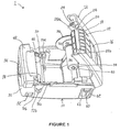
- FIG 1 illustrates a perspective view of a portable printer 1 according to the present invention.
- the portable printer 1 has a main body 10 and a door 12 pivotally coupled to the main body 10 at a back end.
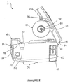
- a pivot shaft 64 threads through meshing teeth 66, 68 respectively of the door 12 and the main body 10 to pivotally connect them at the back end of the portable printer 1, as shown in Figures 2, 3.
- the door 12 may be opened up to approximately 80° for accessing inside the main body 10 of the portable printer 1.
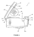
- a holding rack 42 extends perpendicularly inward from the underside of the door 12 near the left side for holding a medium roller support 30, as shown in Figure 3.
- the holding rack 42 may be an integrated part of the door 12, or it may be securely attached to the door 12 by a fixing means.
- the holding rack 42 is an integrated part of the door 12 and is made of same materials as of the door 12.
- the medium roller support 30 has a left paddle end 32, a support arm 36, and a neck section 34 integrally connecting the left paddle end 32 and the support arm section 36.
- the overall lateral length of the medium roller support 30 is approximately 4.44 cm (1.75 inches) long.
- the main body 10 has a printing medium room, which is approximately 8.38 cm (3.3 inches) wide, 12.7 cm (5 inches) long, and 5.59 cm (2.2 inches) deep.
- the printing medium room is sufficiently large to house the medium roller support 30, together with a printing medium roll to be mounted thereon.
- the medium roller support 30 may hold the printing medium roll to be housed within printing medium room of the main body 10 during operation.
- the left paddle end 32 of the medium roller support 30 has a flat ring shape having an outer diameter of approximately 5.33 cm (2.1 inches) and an inner diameter of approximately 1.9 cm (0.75 inches).
- the neck section 34 is shaped like a cylindrical tunnel with an outer diameter of approximately 2.16 cm (0.85 inches) and stepped inner diameters of approximately 1.9 cm (0.75 inches) and 1.78 cm (0.7 inches) respectively.
- a first end of the neck section 34 is perpendicularly integrated to the inner diameter of the left paddle end 32, and a second end, opposite to the first, of the neck section 34 is integrally coupled to a first end of the support arm section 36.
- the support arm section 36 also has a cylindrical tunnel shape with an outer diameter of approximately 1.78 cm (0.7 inches) and an inner diameter of approximately 1.27 cm (0.5 inches).
- the neck section 34 and the support arm section 36 together form a stepped-cylindrical room inside the medium roller support 30.
- a roller support shaft 38 is positioned inside throughout the length of the stepped-cylindrical room of the medium roller support 30 such that the medium roller support 30 is rotatably coupled to the roller support shaft 38.
- the roller support shaft 38 has a diameter of approximately 0.63 cm (0.25 inches) and a length of approximately 6.35 cm (2.5 inches) long.
- a second end, opposite to the first, of the support arm section 36 is partially closed and has a shaft hole having a diameter slightly larger than the diameter of the roller support shaft 38 to allow the roller support shaft 38 to thread through.
- the roller support shaft 38 is coupled to the holding rack 42 by a connecting means 44 for holding the medium roller support 30.
- the connecting means 44 includes a screw adapted to screw through a hole of the holding rack 42 into the roller support shaft 38 for securing the roller support shaft 38 and holding the medium roller support 30.
- a coil spring mechanism 31 is positioned within the stepped-cylindrical room of the neck section 34, as shown in Figure 5.
- the coil spring mechanism 31 encircles the roller support shaft 38 allowing the medium roller support 30 to be laterally pressed to the left until the left paddle end 32 is stopped by the holding rack 42.
- other types of elastic mechanisms may be adopted to replace the coil spring mechanism 31.
- the coil spring mechanism 31 has a holding frame with a lateral length of approximately 1.27 cm (0.5 inches) and the roller support shaft 38 is tightly threaded through the holding frame of the coil spring mechanism 31 horizontally.
- the roller support shaft 38 has a circular groove near a second end, opposite to the first, for receiving a stop 40 fitted onto the circular groove.
- the stop 40 has a generally ring shape having an opening wherein two extrusions respectively extend outwardly from opposite sides of the opening. The two extrusions of the stop 40 help grasp and expand the ring-shape stop 40 for installing or uninstalling onto the circular groove.
- the outer diameter of the stop 40 extends slightly outward of the roller support shaft 38, but no part of the stop 40 will extend beyond the outer diameter of the support arm 36.
- the stop 40 is made of metallic materials. However, any other suitable materials may be used for making the stop 40.
- the coil spring mechanism 31 urges the second end of the support arm 36 against the stop 40. Because the stop 40 is fitted onto the circular groove of the roller support shaft 38 and cannot move laterally outside of the circular groove, the stop 40 therefore prevents the medium roller support 30 from falling off the roller support shaft 38. As noted, the horizontal length of the medium roller support 30 is shorter than the lateral length of the roller support shaft 38. Therefore, the medium roller support 30 may move laterally along the roller support shaft 38 between the stop 40 and the holding rack 42 by pressing back against the coil spring mechanism 31.
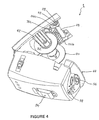
- a right paddle end 80 may be positioned at the second end, i.e., the right end, of the roller support shaft 38, as shown in Figure 4. The right paddle end 80 functions to prevent the printing medium roll mounted on the medium roller support 30 from falling off the medium roller support 30.
- An opening 16 is positioned on a top surface 14 of the door 12.
- the opening 16 is approximately 4.44 cm (1.75 inches) wide and 2.29 cm (0.9 inches) long and is partially above the medium roller support 30 mounted on the door 12.
- a user may check the status of the printing medium roll held by the medium roller support 30 by looking through the opening 16.
- a rectangular stripping slope 20 is located on the top surface 14 near the front end of the door 12, and a rectangular slot 18 is located on the top surface 14 between the stripping slope 20 and the opening 16.
- the slot 18 is parallel to the stripping slope 20 with a distance of approximately 0.25 cm (0.1 inches) between them.
- An optional transparent lid (not shown) may also be positioned on the top surface 14.
- the transparent lid has a size similar to the size of the opening 16 so that it may cover the opening 16 to prevent dusts from entering into the printer 1.
- the slot 18 is approximately 5.59 cm (2.2 inches) wide and 0.41 cm (0.16 inches) long.
- the stripping slope 20 is approximately 5.59 cm (2.2 inches) wide and 1.22 cm (0.48 inches) long. Beginning from the top surface 14 near the slot 18, the stripping slope 20 angles downward toward the front end by approximately 40° relative to the horizontal top surface 14 having a slop length of approximately 1.22 cm (0.48 inches).
- the printing medium roll such as a label roll
- the printing medium roll is typically formed by winding a continuous strip of printing medium, such as a label strip having labels attached to a continuous strip of protective backing, over a cylindrical roll holder.
- the label roll is first mounted on the medium roller support 30 by inserting the cylindrical roll holder onto the neck section 34 and the support arm section 36.
- the label strip is pulled from the label roll toward the front end of the main body 10 and is then turned backward over a platen 24, as shown in Figure 6.
- the protective backing has a gloss surface facing the labels allowing the labels to be peeled off effortlessly.
- the labels are glued to the protective backing, but the adhesive force of the glue is not very strong so that when the label strip is bent over a critical angle, e.g., 30°, the label right over the bent will part from the protective backing and will move tangentially with respect to the protective backing.
- the protective backing moves downward to be threaded between a roller 82 and the platen 24 and then proceeds upward to come out of the top surface 14 through the slot 18.
- the positions of the platen 24, the roller 82, and the slot 18 are properly arranged to cause the label strip to be bent over the critical angle.
- the platen 24 has a cylindrically shaped pressing member having an outer diameter of approximate 0.89 cm (0.35 inches) and a length of approximately 5.51 cm (2.17 inches).
- the pressing member of the platen 24 tightly encircles a platen shaft 25, which has a diameter of approximately 0.41 cm (0.16 inches) and a length of approximately 7.42 cm (2.92 inches).
- the pressing member of the platen 24 and the platen shaft 25 may be respectively made of any suitable materials that are widely known by persons skilled in the art.
- the roller 82 has a roller pressing member made of Teflon materials with an outer diameter of approximately 0.74 cm (0.29 inches) and a length of approximately 5.33 cm (2.1 inches).
- the roller pressing member of the roller 82 also tightly encircles a roller shaft 83 having a diameter of approximately 0.33 cm (0.13 inches) and a length of approximately 6.81 cm (2.68 inches).
- the labels will move tangentially with respective to the protective backing when they are passing the bending point where the protective backing starts to be threaded downward between the roller 82 and the platen 24.
- the stripping slope 20 is positioned above the roller 82 and the angle of the stripping slope 20 is chosen such that the labels will move roughly parallel to and over the stripping slope 20 after the labels move past the bending point.
- the labels will be automatically parted from the protective backing after passing the platen 24 and will come out of the top surface 14 from over the stripping slope 20, while the protective backing will come out of the top surface 14 through the slot 18.
- the slot 18 and the stripping slope 20 jointly function to separate labels and the protective backing after the labels have been printed.
- a plurality of ridges are positioned on the stripping slope 20.
- Each of the ridges 22 has a very narrow width and they extend perpendicular outward from the stripping slope 20 for approximately 0.13 cm (.05 inches).
- the ridges 22 of the stripping slope 20 help prevent the printed labels from sticking to the stripping slope 20.
- the labels may smoothly come out of the portable printer 1 over the stripping slope 20, and the protective backing will come out of the portable printer 1 through the slot 18. As a result, the user needs not to manually peel the label off the protective backing.
- a door locking mechanism 26 is positioned at an underside of the door 12, partly under the stripping slope 20.
- the door locking mechanism 26 has a pair of door locking latches 26a, 26b positioned at opposite ends (left and right) of the door 12, as shown in Figure 1.
- a pair of platen receptive holes are respectively positioned on the door locking latches 26a, 26b.
- the platen 24 is positioned between the door locking latches 26a, 26b and has the platen shaft 25 rotatably coupled to the door locking mechanism 26 through the respective platen receptive holes of the door locking latches 26a, 26b.
- Diameters of the platen receptive holes are slightly larger than a diameter of the platen shaft 25 to allow approximately 6.60 cm (2.6 inches) away from each other to allow some lateral movement of the platen 24 between the door locking latches 26a, 26b.
- the platen shaft 25 is further coupled to a gear 28 positioned at the outer side of the left door locking latch 26a, opposite to the side of the pressing member of the platen 24.
- the platen 24 tightly presses the printing medium against the roller 82 during operation.
- the gear 28 is adapted to rotate the platen 24 so that the platen 24 and the roller 82 may move the printing medium through the printer 1.
- Each of the door locking latches 26a, 26b has an extrusion part respectively facing toward the front end of the portable printer 1 when the door 12 is closed.
- the extrusion parts of the door locking latches 26a, 26b respectively has a cam shape at the front end and a recess having an approximately flap top surface functioning as a latch to lock the door 12 to the main body 10, which will be explained in more detailed
- the roller 82 is movably and rotatably positioned under the stripping slope 20 and is approximately parallel to the platen 24, as shown in Figures 5 and 6.
- the roller shaft 83 of the roller 82 is threaded through two roller receptive holes respectively positioned on the door locking latches 26a, 26b and approximately under the slot 18.
- the roller receptive holes of the door locking latches 26a, 26b are of approximately elliptic shape and are larger than the diameter of the roller's shaft to allow the roller 82 to press against or move away from the platen 24.
- a pair (left and right) of stripper arms 74a, 74b are rotatably coupled to the respective door locking latches 26a, 26b, as shown in Figures 2, 3, and 4.
- the left and right stripper arms 74a, 74b extend behind the roller 82 and are adapted to urge the roller 82 against the platen 24.
- a pair of plungers 76a, 76b is located in the main body 10 respectively at left and right ends of the main body 10 corresponding to the positions of the left and right stripper arms 74a, 74b.
- the plungers 76a, 76b are approximately cylindrically shaped and are housed in their respective pole rooms in the main body 10, as shown in Figure 1. Inside the pole rooms, two coil spring means respectively positioned under the plungers 76a, 76b to urge the plungers 76a, 76b upward and extending outside of the respective pole rooms.
- each plunger 76a or 76b that extends outside of the respective pole room is approximately 0.35 inches long, which is sufficient to contact and push the respective stripper arm 74a or 74b upward when the door 12 is closed against the main body 10. Therefore, the plungers 76a, 76b are positioned corresponding to the stripper arms 74a, 74b such that the plungers 76a, 76b may push the respective stripper arms 74a, 74b, which, in turn, urge the roller 82 against the platen 24 when the door 12 is closed against the main body 10. Conversely, when the door 12 is opened from the main body 10, the plungers 76a, 76b will be separated from the stripper arms 74a, 74b. Thus, stripper arms 74a, 74b are released from pushing the roller 82 against the platen 24, and the user may easily thread the protective backing between the roller 82 and the platen 24.
- a support frame 78 is positioned inside the front end of the main body 10.
- the support frame 78 has two frame side plates respectively positioned at opposite ends (left and right), and a central plate perpendicularly coupled between both frame side plates.
- a support frame shaft (not shown), of approximately 2.76 inches, is threaded through both frame side plates near their respective bottom ends.
- a body locking mechanism 48 also has two body side plates (left and right) respectively positioned parallel to and outside of the left and right frame side plates of the support frame 78. The left and right body side plates of the body locking mechanism 48 are also threaded through by the support frame shaft so that the body locking mechanism 48 is pivotally coupled to the support frame 78.
- the body locking mechanism 48 covers a top front corner of the portable printer 1 and has a pair of body locking latches 70a, 70b respectively positioned on the left and right body side plates near the top.
- the body locking laches 70a, 70b are also positioned corresponding to the positions of the pair of door locking latches 26a, 26b respectively.
- the body locking latches 70a, 70b Similar to the door locking latches 26a, 26b, the body locking latches 70a, 70b, have extrusion parts respectively extending toward the back end.
- Each of the extrusion parts of the respective body locking latches 70a, 70b has a cam shape at the back end to allow sliding against the respective cam-shaped extrusion parts of the door locking latches 26a, 26b.
- the extrusion parts of the respective body locking latches 70a, 70b also respectively has a recess having an approximately flat surface facing down to latch the respective recess of the door locking latches 26a, 26b.
- the recesses of the door locking laches 26a, 26b are of L-shape and the recesses of the body locking mechanism 48 are of ⁇ -shape.
- the body locking latches 70a, 70b are properly positioned relative to the door locking latches 26a, 26b such that the respective door and body locking latches may latch with each other when the door 12 is closed against the main body 10.
- a print head 50 is secured to a support rack 84, as shown in Figure 5.
- the support rack 84 has a left and right small extrusion rods respectively positioned at opposite ends (left and right).
- the extrusion rods of the support rack 84 respectively extends through two print head receptive holes respectively positioned on the left and right frame side plates of the support frame 78.
- the extrusion rods of the support rack 84 respectively has a diameter of approximately 0.25 cm (0.1 inches), and the print head receptive holes could have any shape sufficiently large to house the extrusion rods and to allow movements therein. Therefore, the extrusion rods of the support rack 84 may move freely within the print head receptive holes, and the print head 50 will move accordingly.
- extrusion rods of the support rack 84 are also threaded through a pair of latching holes positioned on the body side plates respectively.
- the body side plates of the body locking mechanism 48 will pull the print head 50 toward the front end to help unlock the door 12 from the main body 10.
- An elastic mechanism 86 is coupled between the central plate of the support frame 78 and the support rack 84, as shown in Figure 5.
- the elastic mechanism 86 urges the print head 50 toward the back end of the portable printer 1, but the orientation of the print head 50 may be freely adjusted by pressing against the elastic mechanism 86.
- the print head 50 is also slightly movable vertically relative to the support frame 78 due to the larger size of the print head receptive holes relative to the diameter of the extrusion rods of the support rack 84.
- the elastic mechanism 86 in conjunction with the print head receptive holes, makes the print head 50 essentially "float" against the support frame 78.
- the elastic mechanism 86 includes a pair of coil springs, but any other alternative elastic mechanisms that serve the purpose may be adopted to accomplish the similar floating result.
- the central plate of the support frame 78 has two extrusion rods at the back side and the support rack 84 correspondingly has two extrusion rods at the front side facing directly against the respective extrusion rods of the support frame 78.
- the pair of the corresponding extrusion rods of the support frame 78 and the support rack 84 confines the corresponding coil spring therein between.
- Each of the coil springs in the preferred embodiment exerts an urging force of approximately 0.536 kg/cm (3.0 lb/inch) between the print head 50 and the support frame 78.
- the urging forces of the coil springs determine how much force a user needs to press the body locking mechanism 48 against the coil springs for releasing the door 12.
- the urging forces of the coil springs also determine an adjustability of the print head 50 relative to the platen 24, as will be further elaborated in the following paragraphs.
- the elastic mechanism 86 is positioned between the support rack 84 and the central plate of the support frame 78, that is behind the front end of the main body 10, to urge the support rack 84, and thus the print head 50, toward the back end of the portable printer 1. Furthermore, extrusion rods at each ends (left and right) of the support rack 84 are inserted into the left and right latching holes of the body side plates respectively. Thus, the support rack 84 will push the body locking latches 70a, 70b of the body locking mechanism 48 backward to keep the door 12 locked when it is closed. Since the body locking mechanism 48 is pivotally coupled to the support frame 78, it can be pressed to move the body locking latches 70a, 70b frontward.
- the user presses the body locking mechanism 48 frontward forcing the support rack 84 to move against the elastic mechanism 86 and to disengage the extrusion parts of the body locking latches 70a, 70b from the extrusion parts of the door locking latches 26a, 26b.
- a security lock 56 is movably positioned on the front panel 55 of the main body 10 to lock or unlock the pressing bar 48, as shown in Figure 1.
- the security lock 56 may be moved up or down along the front panel 55.
- the door locking mechanism 48 is unlocked and can be pressed down to release the door 12.
- the security lock 56 is positioned up, it presses against the door locking mechanism 48 and prevents the door locking mechanism 48 from being pressed down to unlock the door 12.
- the security lock 56 provides a double security for preventing an unintended release of the door 12.
- This double security design is particularly advantageous since a gear mechanism 46, which is coupled to the support frame 78 and will mesh with the gear 28 when the door 12 is closed, tends to urge the door 12 open by pressing the body locking mechanism 48 frontward during operation.
- One of the principal objects of the present invention is to improve the accessibility of the printing medium within a portable printer.
- the present invention mounts the medium roller support 30 on the door 12 to make the medium roller support 30 readily accessible.
- the user of the present invention needs not awkwardly trying to replace the printing medium roll held by a medium roller support coupled to the main body of the conventional portable printer.
- the present invention also positions the print head 50 and the platen 24 in the main body 10 and on the door 12 respectively to further facilitate easy loading and/or replacing of the printing medium roll.
- the configurations of the present invention basically eliminate the need for carefully threading the printing medium between a platen and a print head, as a conventional portable printer often requires.
- These convenient features of the present invention simplify the procedures of replacing a printing medium roll in a portable printer dramatically.
- the present invention automatically separates the labels from the protective backing of the label roll during operation as mentioned above.
- the present invention provides many particular convenient features as compared to the conventional printers.
- a proper alignment of the printing medium relative to the print head 50 is one of the most critical features for having good quality printouts.
- Most conventional portable printers reduce the likelihood of misalignment problems by positioning the platen and the print head on a same bracket to fix their relative position. Since the medium roller support 30 and the platen 24 of the present invention are separate from the main body 10, where the print head 50 is located, the possibility of misalignment between the platen 24 and the print head 50, and thus between the printing medium and the print head 50, increases due to the separation of the platen 24 and the print head 50, as compared to the conventional single-bracket portable printers. This potential misalignment problem, however, is resolved by providing a print head 50 "floating" on the support frame 78 for automatically adjusting the print head position relative to the position of the platen 24 according to the present invention.
- the floating arrangement of the print head 50 allows the print head 50 to be adjustable for a proper alignment with the platen 24.
- the pressing force of the elastic mechanism 86 depends on the strength of components, such as the coil springs, of the elastic mechanism 86 and is carefully selected to provide an adequate pressure on the print head 50 against the platen 24.
- the elastic mechanism 86 will automatically respond to an uneven pressure between the platen 24 and the print head 50 due to the misalignment and will slightly readjust the orientation of the print head 50 to compensate the misalignment.
- the print head receptive holes allow the extrusion rods of the support rack 84 move freely within the print head receptive holes.
- the print head 50 may also be slightly repositioned vertically for a better alignment with the platen 24. As a result, the initial misalignment will be corrected or at least will not deteriorate to cause more misalignment problems during printing.
- the portable printer 1 further includes the gear mechanism 46 locating at the left end of the main body 10.
- a motor 88 positioned within the main body 10 is coupled to the gear mechanism 46 for driving the same.
- the gear mechanism 46 is also positioned relative to the gear 28 of the door 12 so that the gear mechanism 46 will mesh properly with the gear 28 when the door 12 is closed against the main body 10. Therefore, when the door 12 is closed, the motor 88 is coupled to rotate the gear 28 and the platen 24 in order to move the printing medium.
- a wire connector 52 such as a phone jack, may be provided to receive a data transmitting wire (not shown), such as a phone line, for receiving and/or transmitting electronic data for the portable printer 1.
- the wire connector 52 is positioned at the lower right side close to the front of the main body 10.
- a reflective sensor (not shown) may also be mounted on the door 12 at the underside near the opening 16 for sensing the status of the printing medium roll.
- the reflective sensor is coupled to a signal light 58 positioned on the front panel 55.
- the reflective sensor faces perpendicularly to the printing medium roll and could measure the distance between the reflective sensor and the surface of the printing medium roll. When the printing medium roll is unwinding to supply printing medium strip for printing, the distance between the reflective sensor and the printing medium roll increases gradually.
- the reflective sensor will notify the user by sending an end-of-roll signal to the signal light 58 when the distance between the reflective sensor and the printing medium roll reaches a predetermined value.
- the signal light 58 is an LED light.
- the end-of-roll signal may be a sound or any other optical signals, and any type of commercially available reflective sensors may be used for sensing purposes.
- a battery cavity 60 is optionally located at the right side of the main body 10 for receiving a battery or batteries to power the printer 1.
- the battery cavity 60 is covered by a battery cavity door 61 having a door lock 62 for locking or unlocking the battery cavity door 61.
- a lithium ion battery is used, but any other suitable commercially available batteries may be adopted for providing electrical power to the portable printer 1.
- the main body 10 also comprises a pair of semicircle rings 72a, 72b, positioning on opposite sides (left and right) of the main body 10, for hooking the portable printer 1 to a holding means, such as a belt of the user.
- a clip 54 may be fixedly coupled to the main body 10 at the bottom. The clip 54 may be used to clip the portable printer 1 to the holding means.
Landscapes
- Accessory Devices And Overall Control Thereof (AREA)
- Handling Of Sheets (AREA)
Description
- The present invention relates generally to an image producing device and more particularly to a portable printing device having a door-mounted roller support mechanism for easier access to a printing medium roll mounted thereon.
- The conveniences provided by portable printers have made them widely used in the modern business settings for many years. For instance, a person supervising rental car returns often wears a portable printer on his/her belt for printing car rental information or for communicating information to his/her rental car company's main computer. By virtue of carrying a portable printer, the person may print out return information and/or receipts at the parking lot where the rental cars are returned, without the need of going back to the rental office to complete the transactions. The portable printers, thus, save tremendous amounts of time and trouble for customers and they dramatically improve efficiencies of many business transactions.
- There are many different designs of portable printers available on the market. However, only two forms of printing mediums, namely, a separate-sheet form or a medium-roll form, are predominantly used for all printers, whether portable or not. Each printer thus has its specifically designed feeding mechanism to receive either one form of the printing medium, or both. For a typical small-sized portable printer, the medium-roll form is the principal printing medium form used.
- The printing medium may be made of sheets of paper or labels attached to protective backings. For the separate-sheet printing medium form, each sheet of paper or each label is separately fed into the printer for printing. Conversely, the medium-roll form of a printing medium is formed by a continuous paper or label strip fed into the printer by a roller feeding mechanism built into the printer. The continuous strip may have periodic perforations to facilitate tearing the strip of the printing medium apart. Alternatively, other tearing mechanisms may be adopted by the printer to tear the strip of the printing medium roll.
- Having a medium roll as the printing medium form is particularly desirable for most portable printers. Preferably, a portable printer should be small and lightweight, as compared to a regular non-portable printer. Moreover, the portable printer is often designed to print simple receipts, or similar business records. Thus, there is less need of using standard-size business papers for the portable paper. In addition, the medium-roll form is easier to handle for a small size printing medium. As a result, most portable printers use the medium-roll form printing mediums.
- A conventional portable printer generally has a print head for forming images on the printing medium, a platen for pressing the printing medium against the print head and for moving the printing medium, a feeding mechanism for feeding the printing medium to the print head, and a door to be opened for accessing or replacing the printing medium. The feeding mechanism often comprises a medium roller for mounting a printing medium roll thereon, and a motor for rotating the platen and/or the medium roller to move the printing medium toward the print head.
- As the printing medium passes through the portable printer, the printing medium needs to be carefully aligned throughout an internal medium path of the portable printer for a good quality printout. The internal medium path starts from the printing medium roll to the print head and the platen until the printing medium comes out of the portable printer. Thus, the platen of the portable printer should be aligned with the print head to press and move the printing medium properly. The medium roller also has to be carefully situated in the portable printer in order to assure the alignment of the printing medium with the print head. Otherwise, skipped printings, double printings, paper jam, and many other problems might happen due to the misalignment problem of the printing medium in the portable printer. As a result, the print head, the platen, and the medium roller are typically positioned in the vicinity of each other, and a conventional portable printer typically has a single bracket for holding the print head and the platen together to reduce the likelihood of misalignment problems.
- Placing the print head and the platen on a single bracket does reduce the likelihood of misalignment problems for a conventional portable printer. It, however, has drawbacks of inconvenience in replacing the printing medium, for it necessitates threading the printing medium between the print head and the platen. Also, the medium roller of the conventional printer is often positioned inside the portable printer and is hard to reach. Thus, to replace a printing medium in the conventional portable printer, a user has to open the printer door, take off a used printing medium roll, insert a new printing medium roll, carefully thread the strip of the new medium roll between the platen and the print head, and then close the door of the portable printer. These steps, taken as a whole, are quite time-consuming to perform. It is particularly inconvenient if the portable printer is mounted on the belt of the user, such as the person supervising the rental car returns. To replace the printing medium roll in the conventional portable printer, that person will necessarily have to take the printer off the belt and have it reinstalled on the belt after reloading the printing medium roll.
- US-A-4860031 discloses a transport device for a register tape of an electric register mechanism having a housing containing a supply load unit into which a supply roller serving for unwinding the register tape is insertable, and a transport roller which, together with a contact pressure roller, grips a register tape running between both the transport roller and the contact pressure roller and passes it from the supply roller unit to and beyond a register element of the register mechanism for performing a recording on the register tape. The supply unit is at least partly removable from the housing for inserting the supply roller therein.
- An object of the present invention is to provide a mechanism to a portable printer for conveniently replacing the printing medium roll without running into the misalignment problems which typically happen to a conventional portable printer. This object is met by providing a door mounted roller support together with an automated dispense mode engagement according to the present invention, as indicated in the claims appended hereto.
- In summary, the present invention comprises a portable printer having a medium roller support mounted on a door of the portable printer. The portable printer also comprises a platen positioned on the door and a print head positioned on a main body of the portable printer. The print head is movably supported by a suspension mechanism. Thus, the print head could be properly aligned with the platen when the printer door is closed to the main body. The present invention may also have a gearing mechanism functioning to rotate the platen for moving the printing medium.
- In detail, therefore, the present invention provides a printer (1) including a body (10) adapted to house a mounted roll of print media having a protective backing which is removed from the print media after an image is printed on the print media, wherein the printer comprises:
- a door (12) pivotally coupled at one end to the body; the door being adapted to rotate between an open position for providing access to the mounted print media roll and a dosed position enclosing the mounted print media roll within the body;
- a rotating platen (24) rotatably coupled to the door such that the platen is in an operative position inside the body when the door is dosed and is withdrawn from the interior of the body when the door is open;
- a printhead (50) movably coupled to the body for forming images on the print media, the printhead being movable relative to and adapted to automatically align with the rotating platen for preventing misalignment with the platen and the print media when the platen is in the operative position and supporting the print media;
- a roll holder (30) coupled to the door for mounting and holding the print media roll such that the mounted print media roll is inside the printer body when the door is dosed and is outside the printer body when the print media roll is being mounted and dismounted, and
- a stripper mechanism coupled to the door for separating the print media from the
protective backing after an image has been printed, the striper mechanism
comprising:
- a pinch roller (82) rotatably coupled to the door;
- at least one stripper arm (74) responsive to the movement of the door between its open position and its closed position for pushing the peeler roller against the platen when the door is in the closed position and for allowing the pinch roller to move away from the platen when the door is open; and
- a bending point (unnumbered, Fig 6) on the door disposed adjacent the platen downstream from the printhead and upstream from the pinch roller for separating the print media from the protective backing; whereby when the door is open the print media roll may be mounted and dismounted from the roll holder and the protective backing may be threaded between the exposed platen and the exposed pinch roller, and
-
- Preferably, the stripping mechanism further includes a stripping section (20) on the door disposed over the peeler roller and adapted to allow separated print media to move parallel to and over the stripping section after passing past the bending point. This stripping section preferably includes a plurality of ridges adapted to prevent separated print media from sticking to the stripping section. The stripper mechanism may further include a protective backing exit slot (18) on the door disposed substantiate parallel to the stripping section.
- Preferably, the printer further comprises a support frame (78) coupled to a front portion of the printer body opposite the pivotally coupled door end, a printhead support rack (84) moveably coupled to the support frame, the printhead being securely coupled to the printhead support rack, and an elastic mechanism (86) coupled between the printhead support rack and the support frame and adapted to allow the printhead to float against the support frame.
- The printer may comprise a printer body locking mechanism (48) pivotally coupled to the support frame.
- The printer may also comprise a body gear mechanism coupled to a motor housed within the body and a door gear mechanism operatively coupled between the body gear mechanism and one end of the platen for rotatably driving the platen when the door is in the dosed position.
- Preferably, the printer is adapted to receive and transmit electronic data.
- Preferably, the printer is adapted to be powered by a battery.
- The printer may also comprise a print media status sensor coupled to the door proximate to the mounted print media roll.
- The print media roll mounting and holding means may include a spring-loaded print media roll support arm rotatably coupled to the door between the platen and the pivotally coupled door end and adapted to hold the mounted print media roll.
- The foregoing and additional features and advantages of this present invention will become apparent by way of non-limitative examples shown in the accompanying drawings and detailed description that follow. In the figures and written description, numerals indicate the various features of the invention, like numerals referring to like features throughout for both the drawing figures and the written description.
-
- Figure 1 shows a perspective view of a portable printer according to the present invention.
- Figure 2 shows a right side elevational view of the portable printer of Figure 1.
- Figure 3 shows a left side elevational view of the portable printer of Figure 1.
- Figure 4 shows a perspective view from lower left side of the portable printer of Figure 1.
- Figure 5 shows a cross-section elevational view of the portable printer of Figure 1.
- Figure 6 shows a cross-sectional view illustrating a protective backing and a label of a label roll separated by a roller and a platen of the portable printer of Figure 1.
-
- Figure 1 illustrates a perspective view of a
portable printer 1 according to the present invention. In Figure 1, theportable printer 1 has amain body 10 and adoor 12 pivotally coupled to themain body 10 at a back end. Apivot shaft 64 threads through meshingteeth door 12 and themain body 10 to pivotally connect them at the back end of theportable printer 1, as shown in Figures 2, 3. Thus, thedoor 12 may be opened up to approximately 80° for accessing inside themain body 10 of theportable printer 1. - A holding
rack 42 extends perpendicularly inward from the underside of thedoor 12 near the left side for holding amedium roller support 30, as shown in Figure 3. The holdingrack 42 may be an integrated part of thedoor 12, or it may be securely attached to thedoor 12 by a fixing means. In a preferred embodiment, the holdingrack 42 is an integrated part of thedoor 12 and is made of same materials as of thedoor 12. - Shown in Figure 1, the
medium roller support 30 has aleft paddle end 32, asupport arm 36, and a neck section 34 integrally connecting theleft paddle end 32 and thesupport arm section 36. The overall lateral length of themedium roller support 30 is approximately 4.44 cm (1.75 inches) long. Themain body 10 has a printing medium room, which is approximately 8.38 cm (3.3 inches) wide, 12.7 cm (5 inches) long, and 5.59 cm (2.2 inches) deep. The printing medium room is sufficiently large to house themedium roller support 30, together with a printing medium roll to be mounted thereon. Thus, when thedoor 12 is closed, themedium roller support 30 may hold the printing medium roll to be housed within printing medium room of themain body 10 during operation. - The
left paddle end 32 of themedium roller support 30 has a flat ring shape having an outer diameter of approximately 5.33 cm (2.1 inches) and an inner diameter of approximately 1.9 cm (0.75 inches). The neck section 34 is shaped like a cylindrical tunnel with an outer diameter of approximately 2.16 cm (0.85 inches) and stepped inner diameters of approximately 1.9 cm (0.75 inches) and 1.78 cm (0.7 inches) respectively. A first end of the neck section 34 is perpendicularly integrated to the inner diameter of theleft paddle end 32, and a second end, opposite to the first, of the neck section 34 is integrally coupled to a first end of thesupport arm section 36. Thesupport arm section 36 also has a cylindrical tunnel shape with an outer diameter of approximately 1.78 cm (0.7 inches) and an inner diameter of approximately 1.27 cm (0.5 inches). Thus, the neck section 34 and thesupport arm section 36 together form a stepped-cylindrical room inside themedium roller support 30. - A
roller support shaft 38 is positioned inside throughout the length of the stepped-cylindrical room of themedium roller support 30 such that themedium roller support 30 is rotatably coupled to theroller support shaft 38. Theroller support shaft 38 has a diameter of approximately 0.63 cm (0.25 inches) and a length of approximately 6.35 cm (2.5 inches) long. Furthermore, a second end, opposite to the first, of thesupport arm section 36 is partially closed and has a shaft hole having a diameter slightly larger than the diameter of theroller support shaft 38 to allow theroller support shaft 38 to thread through. At a first end near theleft paddle end 32, theroller support shaft 38 is coupled to theholding rack 42 by a connectingmeans 44 for holding themedium roller support 30. In the preferred embodiment, the connectingmeans 44 includes a screw adapted to screw through a hole of the holdingrack 42 into theroller support shaft 38 for securing theroller support shaft 38 and holding themedium roller support 30. - In the preferred embodiment, a coil spring mechanism 31 is positioned within the stepped-cylindrical room of the neck section 34, as shown in Figure 5. The coil spring mechanism 31 encircles the
roller support shaft 38 allowing themedium roller support 30 to be laterally pressed to the left until theleft paddle end 32 is stopped by the holdingrack 42. In alternative embodiments, other types of elastic mechanisms may be adopted to replace the coil spring mechanism 31. The coil spring mechanism 31 has a holding frame with a lateral length of approximately 1.27 cm (0.5 inches) and theroller support shaft 38 is tightly threaded through the holding frame of the coil spring mechanism 31 horizontally. - In one embodiment, the
roller support shaft 38 has a circular groove near a second end, opposite to the first, for receiving astop 40 fitted onto the circular groove. Thestop 40 has a generally ring shape having an opening wherein two extrusions respectively extend outwardly from opposite sides of the opening. The two extrusions of thestop 40 help grasp and expand the ring-shape stop 40 for installing or uninstalling onto the circular groove. When mounted on theroller support shaft 38, the outer diameter of thestop 40 extends slightly outward of theroller support shaft 38, but no part of thestop 40 will extend beyond the outer diameter of thesupport arm 36. In one embodiment, thestop 40 is made of metallic materials. However, any other suitable materials may be used for making thestop 40. The coil spring mechanism 31 urges the second end of thesupport arm 36 against thestop 40. Because thestop 40 is fitted onto the circular groove of theroller support shaft 38 and cannot move laterally outside of the circular groove, thestop 40 therefore prevents themedium roller support 30 from falling off theroller support shaft 38. As noted, the horizontal length of themedium roller support 30 is shorter than the lateral length of theroller support shaft 38. Therefore, themedium roller support 30 may move laterally along theroller support shaft 38 between thestop 40 and theholding rack 42 by pressing back against the coil spring mechanism 31. In an alternative embodiment, aright paddle end 80 may be positioned at the second end, i.e., the right end, of theroller support shaft 38, as shown in Figure 4. The right paddle end 80 functions to prevent the printing medium roll mounted on themedium roller support 30 from falling off themedium roller support 30. - An
opening 16 is positioned on a top surface 14 of thedoor 12. In the preferred embodiment of the present invention, theopening 16 is approximately 4.44 cm (1.75 inches) wide and 2.29 cm (0.9 inches) long and is partially above themedium roller support 30 mounted on thedoor 12. Thus, a user may check the status of the printing medium roll held by themedium roller support 30 by looking through theopening 16. A rectangular strippingslope 20 is located on the top surface 14 near the front end of thedoor 12, and arectangular slot 18 is located on the top surface 14 between the strippingslope 20 and theopening 16. Theslot 18 is parallel to the strippingslope 20 with a distance of approximately 0.25 cm (0.1 inches) between them. An optional transparent lid (not shown) may also be positioned on the top surface 14. The transparent lid has a size similar to the size of theopening 16 so that it may cover theopening 16 to prevent dusts from entering into theprinter 1. Theslot 18 is approximately 5.59 cm (2.2 inches) wide and 0.41 cm (0.16 inches) long. Correspondingly, the strippingslope 20 is approximately 5.59 cm (2.2 inches) wide and 1.22 cm (0.48 inches) long. Beginning from the top surface 14 near theslot 18, the strippingslope 20 angles downward toward the front end by approximately 40° relative to the horizontal top surface 14 having a slop length of approximately 1.22 cm (0.48 inches). - The printing medium roll, such as a label roll, is typically formed by winding a continuous strip of printing medium, such as a label strip having labels attached to a continuous strip of protective backing, over a cylindrical roll holder. To load the label strip in the
portable printer 1, the label roll is first mounted on themedium roller support 30 by inserting the cylindrical roll holder onto the neck section 34 and thesupport arm section 36. The label strip is pulled from the label roll toward the front end of themain body 10 and is then turned backward over aplaten 24, as shown in Figure 6. The protective backing has a gloss surface facing the labels allowing the labels to be peeled off effortlessly. The labels are glued to the protective backing, but the adhesive force of the glue is not very strong so that when the label strip is bent over a critical angle, e.g., 30°, the label right over the bent will part from the protective backing and will move tangentially with respect to the protective backing. After the label strip passes theplaten 24, the protective backing moves downward to be threaded between aroller 82 and theplaten 24 and then proceeds upward to come out of the top surface 14 through theslot 18. As shown in Figure 6, the positions of theplaten 24, theroller 82, and theslot 18 are properly arranged to cause the label strip to be bent over the critical angle. In the preferred embodiment, theplaten 24 has a cylindrically shaped pressing member having an outer diameter of approximate 0.89 cm (0.35 inches) and a length of approximately 5.51 cm (2.17 inches). The pressing member of theplaten 24 tightly encircles aplaten shaft 25, which has a diameter of approximately 0.41 cm (0.16 inches) and a length of approximately 7.42 cm (2.92 inches). The pressing member of theplaten 24 and theplaten shaft 25 may be respectively made of any suitable materials that are widely known by persons skilled in the art. Similarly, theroller 82 has a roller pressing member made of Teflon materials with an outer diameter of approximately 0.74 cm (0.29 inches) and a length of approximately 5.33 cm (2.1 inches). The roller pressing member of theroller 82 also tightly encircles aroller shaft 83 having a diameter of approximately 0.33 cm (0.13 inches) and a length of approximately 6.81 cm (2.68 inches). - As stated, the labels will move tangentially with respective to the protective backing when they are passing the bending point where the protective backing starts to be threaded downward between the
roller 82 and theplaten 24. The strippingslope 20 is positioned above theroller 82 and the angle of the strippingslope 20 is chosen such that the labels will move roughly parallel to and over the strippingslope 20 after the labels move past the bending point. Thus, the labels will be automatically parted from the protective backing after passing theplaten 24 and will come out of the top surface 14 from over the strippingslope 20, while the protective backing will come out of the top surface 14 through theslot 18. As a consequence, theslot 18 and the strippingslope 20 jointly function to separate labels and the protective backing after the labels have been printed. Moreover, a plurality of ridges are positioned on the strippingslope 20. In the preferred embodiment, there are seven ridges on the strippingslope 20, but the number of ridges may vary according to the length of the strippingslope 20. Each of theridges 22 has a very narrow width and they extend perpendicular outward from the strippingslope 20 for approximately 0.13 cm (.05 inches). Theridges 22 of the strippingslope 20 help prevent the printed labels from sticking to the strippingslope 20. Thus, the labels may smoothly come out of theportable printer 1 over the strippingslope 20, and the protective backing will come out of theportable printer 1 through theslot 18. As a result, the user needs not to manually peel the label off the protective backing. - A door locking mechanism 26 is positioned at an underside of the
door 12, partly under the strippingslope 20. The door locking mechanism 26 has a pair of door locking latches 26a, 26b positioned at opposite ends (left and right) of thedoor 12, as shown in Figure 1. A pair of platen receptive holes are respectively positioned on the door locking latches 26a, 26b. Theplaten 24 is positioned between the door locking latches 26a, 26b and has theplaten shaft 25 rotatably coupled to the door locking mechanism 26 through the respective platen receptive holes of the door locking latches 26a, 26b. Diameters of the platen receptive holes are slightly larger than a diameter of theplaten shaft 25 to allow approximately 6.60 cm (2.6 inches) away from each other to allow some lateral movement of theplaten 24 between the door locking latches 26a, 26b. Theplaten shaft 25 is further coupled to agear 28 positioned at the outer side of the leftdoor locking latch 26a, opposite to the side of the pressing member of theplaten 24. Theplaten 24 tightly presses the printing medium against theroller 82 during operation. Thus, thegear 28 is adapted to rotate theplaten 24 so that theplaten 24 and theroller 82 may move the printing medium through theprinter 1. Each of the door locking latches 26a, 26b has an extrusion part respectively facing toward the front end of theportable printer 1 when thedoor 12 is closed. The extrusion parts of the door locking latches 26a, 26b respectively has a cam shape at the front end and a recess having an approximately flap top surface functioning as a latch to lock thedoor 12 to themain body 10, which will be explained in more detailed - As stated, the
roller 82 is movably and rotatably positioned under the strippingslope 20 and is approximately parallel to theplaten 24, as shown in Figures 5 and 6. Theroller shaft 83 of theroller 82 is threaded through two roller receptive holes respectively positioned on the door locking latches 26a, 26b and approximately under theslot 18. The roller receptive holes of the door locking latches 26a, 26b are of approximately elliptic shape and are larger than the diameter of the roller's shaft to allow theroller 82 to press against or move away from theplaten 24. In addition, a pair (left and right) ofstripper arms 74a, 74b are rotatably coupled to the respectivedoor locking latches right stripper arms 74a, 74b extend behind theroller 82 and are adapted to urge theroller 82 against theplaten 24. A pair of plungers 76a, 76b is located in themain body 10 respectively at left and right ends of themain body 10 corresponding to the positions of the left andright stripper arms 74a, 74b. The plungers 76a, 76b are approximately cylindrically shaped and are housed in their respective pole rooms in themain body 10, as shown in Figure 1. Inside the pole rooms, two coil spring means respectively positioned under the plungers 76a, 76b to urge the plungers 76a, 76b upward and extending outside of the respective pole rooms. The portion of each plunger 76a or 76b that extends outside of the respective pole room is approximately 0.35 inches long, which is sufficient to contact and push therespective stripper arm 74a or 74b upward when thedoor 12 is closed against themain body 10. Therefore, the plungers 76a, 76b are positioned corresponding to thestripper arms 74a, 74b such that the plungers 76a, 76b may push therespective stripper arms 74a, 74b, which, in turn, urge theroller 82 against theplaten 24 when thedoor 12 is closed against themain body 10. Conversely, when thedoor 12 is opened from themain body 10, the plungers 76a, 76b will be separated from thestripper arms 74a, 74b. Thus,stripper arms 74a, 74b are released from pushing theroller 82 against theplaten 24, and the user may easily thread the protective backing between theroller 82 and theplaten 24. - Referring to Figure 1, a
support frame 78 is positioned inside the front end of themain body 10. Thesupport frame 78 has two frame side plates respectively positioned at opposite ends (left and right), and a central plate perpendicularly coupled between both frame side plates. A support frame shaft (not shown), of approximately 2.76 inches, is threaded through both frame side plates near their respective bottom ends. Abody locking mechanism 48 also has two body side plates (left and right) respectively positioned parallel to and outside of the left and right frame side plates of thesupport frame 78. The left and right body side plates of thebody locking mechanism 48 are also threaded through by the support frame shaft so that thebody locking mechanism 48 is pivotally coupled to thesupport frame 78. Thebody locking mechanism 48 covers a top front corner of theportable printer 1 and has a pair of body locking latches 70a, 70b respectively positioned on the left and right body side plates near the top. The body locking laches 70a, 70b are also positioned corresponding to the positions of the pair of door locking latches 26a, 26b respectively. Similar to the door locking latches 26a, 26b, the body locking latches 70a, 70b, have extrusion parts respectively extending toward the back end. Each of the extrusion parts of the respective body locking latches 70a, 70b has a cam shape at the back end to allow sliding against the respective cam-shaped extrusion parts of the door locking latches 26a, 26b. The extrusion parts of the respective body locking latches 70a, 70b also respectively has a recess having an approximately flat surface facing down to latch the respective recess of the door locking latches 26a, 26b. The recesses of thedoor locking laches body locking mechanism 48 are of ┐-shape. The body locking latches 70a, 70b are properly positioned relative to the door locking latches 26a, 26b such that the respective door and body locking latches may latch with each other when thedoor 12 is closed against themain body 10. - A
print head 50 is secured to asupport rack 84, as shown in Figure 5. Thesupport rack 84 has a left and right small extrusion rods respectively positioned at opposite ends (left and right). The extrusion rods of thesupport rack 84 respectively extends through two print head receptive holes respectively positioned on the left and right frame side plates of thesupport frame 78. The extrusion rods of thesupport rack 84 respectively has a diameter of approximately 0.25 cm (0.1 inches), and the print head receptive holes could have any shape sufficiently large to house the extrusion rods and to allow movements therein. Therefore, the extrusion rods of thesupport rack 84 may move freely within the print head receptive holes, and theprint head 50 will move accordingly. In addition, the extrusion rods of thesupport rack 84 are also threaded through a pair of latching holes positioned on the body side plates respectively. Thus, when the user presses thebody locking mechanism 48, the body side plates of thebody locking mechanism 48 will pull theprint head 50 toward the front end to help unlock thedoor 12 from themain body 10. - An
elastic mechanism 86 is coupled between the central plate of thesupport frame 78 and thesupport rack 84, as shown in Figure 5. Theelastic mechanism 86 urges theprint head 50 toward the back end of theportable printer 1, but the orientation of theprint head 50 may be freely adjusted by pressing against theelastic mechanism 86. Theprint head 50 is also slightly movable vertically relative to thesupport frame 78 due to the larger size of the print head receptive holes relative to the diameter of the extrusion rods of thesupport rack 84. Thus, theelastic mechanism 86, in conjunction with the print head receptive holes, makes theprint head 50 essentially "float" against thesupport frame 78. In a preferred embodiment, theelastic mechanism 86 includes a pair of coil springs, but any other alternative elastic mechanisms that serve the purpose may be adopted to accomplish the similar floating result. The central plate of thesupport frame 78 has two extrusion rods at the back side and thesupport rack 84 correspondingly has two extrusion rods at the front side facing directly against the respective extrusion rods of thesupport frame 78. The pair of the corresponding extrusion rods of thesupport frame 78 and thesupport rack 84 confines the corresponding coil spring therein between. Each of the coil springs in the preferred embodiment exerts an urging force of approximately 0.536 kg/cm (3.0 lb/inch) between theprint head 50 and thesupport frame 78. The urging forces of the coil springs determine how much force a user needs to press thebody locking mechanism 48 against the coil springs for releasing thedoor 12. The urging forces of the coil springs also determine an adjustability of theprint head 50 relative to theplaten 24, as will be further elaborated in the following paragraphs. - As noted, the
body locking mechanism 48 is pivotally coupled to thesupport frame 78 of themain body 10. When thedoor 12 is closing, the extrusion parts of door locking latches 26a, 26b will initially push the extrusion parts of the body locking latches 70a, 70b, and the wholebody locking mechanism 48, frontward until thebody locking mechanism 48 snaps back due to the meshing of the respective recesses of both lockingmechanisms 26, 48. The recesses of thebody locking mechanism 48 press the recesses of the door locking mechanisms 26 downward to latch thedoor 12 with themain body 10. The surfaces of the recesses are flat and can slide against each other for locking and/or unlocking thedoor 12. Theelastic mechanism 86 is positioned between thesupport rack 84 and the central plate of thesupport frame 78, that is behind the front end of themain body 10, to urge thesupport rack 84, and thus theprint head 50, toward the back end of theportable printer 1. Furthermore, extrusion rods at each ends (left and right) of thesupport rack 84 are inserted into the left and right latching holes of the body side plates respectively. Thus, thesupport rack 84 will push the body locking latches 70a, 70b of thebody locking mechanism 48 backward to keep thedoor 12 locked when it is closed. Since thebody locking mechanism 48 is pivotally coupled to thesupport frame 78, it can be pressed to move the body locking latches 70a, 70b frontward. To open thedoor 12, the user presses thebody locking mechanism 48 frontward forcing thesupport rack 84 to move against theelastic mechanism 86 and to disengage the extrusion parts of the body locking latches 70a, 70b from the extrusion parts of the door locking latches 26a, 26b. - A
security lock 56 is movably positioned on thefront panel 55 of themain body 10 to lock or unlock thepressing bar 48, as shown in Figure 1. Thesecurity lock 56 may be moved up or down along thefront panel 55. When thesecurity lock 56 is positioned down, thedoor locking mechanism 48 is unlocked and can be pressed down to release thedoor 12. When thesecurity lock 56 is positioned up, it presses against thedoor locking mechanism 48 and prevents thedoor locking mechanism 48 from being pressed down to unlock thedoor 12. Thus, in conjunction with the latches 70a, 70b of thebody locking mechanism 48, thesecurity lock 56 provides a double security for preventing an unintended release of thedoor 12. This double security design is particularly advantageous since agear mechanism 46, which is coupled to thesupport frame 78 and will mesh with thegear 28 when thedoor 12 is closed, tends to urge thedoor 12 open by pressing thebody locking mechanism 48 frontward during operation. - One of the principal objects of the present invention is to improve the accessibility of the printing medium within a portable printer. To accomplish this, the present invention mounts the
medium roller support 30 on thedoor 12 to make themedium roller support 30 readily accessible. As compared to the conventional portable printer, the user of the present invention needs not awkwardly trying to replace the printing medium roll held by a medium roller support coupled to the main body of the conventional portable printer. The present invention also positions theprint head 50 and theplaten 24 in themain body 10 and on thedoor 12 respectively to further facilitate easy loading and/or replacing of the printing medium roll. Since theprint head 50 and theplaten 24 are widely separate when thedoor 12 is opened, the configurations of the present invention basically eliminate the need for carefully threading the printing medium between a platen and a print head, as a conventional portable printer often requires. These convenient features of the present invention simplify the procedures of replacing a printing medium roll in a portable printer dramatically. In addition, the present invention automatically separates the labels from the protective backing of the label roll during operation as mentioned above. Thus, the present invention provides many particular convenient features as compared to the conventional printers. - A proper alignment of the printing medium relative to the
print head 50 is one of the most critical features for having good quality printouts. Most conventional portable printers reduce the likelihood of misalignment problems by positioning the platen and the print head on a same bracket to fix their relative position. Since themedium roller support 30 and theplaten 24 of the present invention are separate from themain body 10, where theprint head 50 is located, the possibility of misalignment between theplaten 24 and theprint head 50, and thus between the printing medium and theprint head 50, increases due to the separation of theplaten 24 and theprint head 50, as compared to the conventional single-bracket portable printers. This potential misalignment problem, however, is resolved by providing aprint head 50 "floating" on thesupport frame 78 for automatically adjusting the print head position relative to the position of theplaten 24 according to the present invention. - The floating arrangement of the
print head 50 allows theprint head 50 to be adjustable for a proper alignment with theplaten 24. The pressing force of theelastic mechanism 86 depends on the strength of components, such as the coil springs, of theelastic mechanism 86 and is carefully selected to provide an adequate pressure on theprint head 50 against theplaten 24. When an initial misalignment occurs between theprint head 50 and theplaten 24, theelastic mechanism 86 will automatically respond to an uneven pressure between theplaten 24 and theprint head 50 due to the misalignment and will slightly readjust the orientation of theprint head 50 to compensate the misalignment. As mentioned, the print head receptive holes allow the extrusion rods of thesupport rack 84 move freely within the print head receptive holes. Thus, theprint head 50 may also be slightly repositioned vertically for a better alignment with theplaten 24. As a result, the initial misalignment will be corrected or at least will not deteriorate to cause more misalignment problems during printing. - Referring to Figure 1, the
portable printer 1 further includes thegear mechanism 46 locating at the left end of themain body 10. Amotor 88 positioned within themain body 10 is coupled to thegear mechanism 46 for driving the same. Thegear mechanism 46 is also positioned relative to thegear 28 of thedoor 12 so that thegear mechanism 46 will mesh properly with thegear 28 when thedoor 12 is closed against themain body 10. Therefore, when thedoor 12 is closed, themotor 88 is coupled to rotate thegear 28 and theplaten 24 in order to move the printing medium. - A
wire connector 52, such as a phone jack, may be provided to receive a data transmitting wire (not shown), such as a phone line, for receiving and/or transmitting electronic data for theportable printer 1. In the preferred embodiment, thewire connector 52 is positioned at the lower right side close to the front of themain body 10. A reflective sensor (not shown) may also be mounted on thedoor 12 at the underside near theopening 16 for sensing the status of the printing medium roll. The reflective sensor is coupled to asignal light 58 positioned on thefront panel 55. The reflective sensor faces perpendicularly to the printing medium roll and could measure the distance between the reflective sensor and the surface of the printing medium roll. When the printing medium roll is unwinding to supply printing medium strip for printing, the distance between the reflective sensor and the printing medium roll increases gradually. Thus, the reflective sensor will notify the user by sending an end-of-roll signal to thesignal light 58 when the distance between the reflective sensor and the printing medium roll reaches a predetermined value. In the preferred embodiment, thesignal light 58 is an LED light. Alternatively, the end-of-roll signal may be a sound or any other optical signals, and any type of commercially available reflective sensors may be used for sensing purposes. - A
battery cavity 60 is optionally located at the right side of themain body 10 for receiving a battery or batteries to power theprinter 1. Thebattery cavity 60 is covered by abattery cavity door 61 having adoor lock 62 for locking or unlocking thebattery cavity door 61. In the preferred embodiment, a lithium ion battery is used, but any other suitable commercially available batteries may be adopted for providing electrical power to theportable printer 1. Themain body 10 also comprises a pair of semicircle rings 72a, 72b, positioning on opposite sides (left and right) of themain body 10, for hooking theportable printer 1 to a holding means, such as a belt of the user. Additionally, aclip 54 may be fixedly coupled to themain body 10 at the bottom. Theclip 54 may be used to clip theportable printer 1 to the holding means. - From the foregoing, it will be appreciated that, although specific embodiments of the invention have been described herein for purposes of illustration, various modifications may be made by persons skilled in the art without deviating from the spirit and/or scope of the invention. Particularly, other suitable types of door and body locking mechanisms may be adopted to lock the
door 12 to themain body 10. An infrared sensor may also be included to allow theportable printer 1 to transmit electronic data by infrared. Furthermore, the inventive concepts of the present invention may be equally applicable to any portable or non-portable printers and any dimensions of the preferred embodiment may be adjusted accordingly to fit in other alternative embodiments.
whereby when the door is closed, the print media is pressed by the platen against the printhead and the protective backing is separated from the labels as the pinch roller pushing against the rotating platen cooperate to pull the protective backing around the bending point.
Claims (11)
- A printer (1) including a body (10) adapted to house a mounted roll of print media having a protective backing which is removed from the print media after an image is printed on the print media, wherein the printer comprises:whereby when the door is open the print media roll may be mounted and dismounted from the roll holder and the protective backing may be threaded between the exposed platen and the exposed pinch roller, anda door (12) pivotally coupled at one end to the body; the door being adapted to rotate between an open position for providing access to the mounted print media roll and a closed position enclosing the mounted print media roll within the body;a rotating platen (24) rotatably coupled to the door such that the platen is in an operative position inside the body when the door is closed and is withdrawn from the interior of the body when the door is open;a printhead (50) movably coupled to the body for forming images on the print media, the printhead being movable relative to and adapted to automatically align with the rotating platen for preventing misalignment with the platen and the print media when the platen is in the operative position and supporting the print media; median roller support (30) coupled to the door for mounting and holding the print media roll such that the mounted print media roll is inside the printer body when the door is closed and is outside the printer body when the print media roll is being mounted and dismounted, anda stripper mechanism coupled to the door for separating the print media from the protective backing after an image has been printed, the striper mechanism comprising:a pinch roller (82) rotatably- coupled to the door;at least one stripper arm (74) responsive to the movement of the door between its open position and its closed position for pushing the pinch roller against the platen when the door is in the closed position and for allowing the pinch roller to move away from the platen when the door is open; anda bending point on the door disposed adjacent the platen downstream from the printhead and upstream from the pinch roller for separating the print media from the protective backing;
whereby when the door is closed, the print media is pressed by the platen against the printhead and the protective backing is separated from the labels as the pinch roller pushing against the rotating platen cooperate to pull the protective backing around the bending point. - The printer of claim 1, wherein the stripping mechanism further includes a stripping section (20) on the door disposed over the peeler roller and adapted to allow separated print media to move parallel to and over the stripping section after passing past the bending point.
- The printer of claim 2, wherein the stripping section includes a plurality of ridges adapted to prevent separated print media from sticking to the stripping section.
- The printer of claim 2 or 3, wherein the stripper mechanism further includes a protective backing exit slot (18) on the door disposed substantially parallel to the stripping section.
- The printer of any preceding claim, wherein the printer is further characterized by a support frame (78) coupled to a front portion of the printer body opposite the pivotally coupled door end, a printhead support rack (84) moveably coupled to the support frame, the printhead being securely coupled to the printhead support rack, and an elastic mechanism (86) coupled between the printhead support rack and the support frame and adapted to allow the printhead to float against the support frame.
- The printer of claim 4, wherein the printer is further characterized by a printer body locking mechanism (48) pivotally coupled to the support frame.
- The printer of any preceding claim, wherein the printer is further characterized by a body gear mechanism coupled to a motor housed within the body and a door gear mechanism operatively coupled between the body gear mechanism and one end of the platen for rotatably driving the platen when the door is in the closed position.
- The printer of any preceding claim, wherein the printer is adapted to receive and transmit electronic data.
- The printer of any preceding claim, wherein the printer is adapted to be powered by a battery.
- The printer of any preceding claim, wherein the printer is further characterized by a print media status sensor coupled to the door proximate to the mounted print media roll.
- The printer of any preceding claim, wherein the print media roll mounting and holding means includes a spring-loaded print media roll support arm rotatably coupled to the door between the platen and the pivotally coupled door end and adapted to hold the mounted print media roll.
Applications Claiming Priority (4)
| Application Number | Priority Date | Filing Date | Title |
|---|---|---|---|
| US411020 | 1995-03-27 | ||
| US12734899P | 1999-04-01 | 1999-04-01 | |
| US127348P | 1999-04-01 | ||
| US09/411,020 US6261013B1 (en) | 1999-04-01 | 1999-10-04 | Door mounted roll support |
Publications (2)
| Publication Number | Publication Date |
|---|---|
| EP1052109A1 EP1052109A1 (en) | 2000-11-15 |
| EP1052109B1 true EP1052109B1 (en) | 2004-06-16 |
Family
ID=26825563
Family Applications (1)
| Application Number | Title | Priority Date | Filing Date |
|---|---|---|---|
| EP00200385A Revoked EP1052109B1 (en) | 1999-04-01 | 2000-02-07 | Portable marker device with door mounted roller support |
Country Status (3)
| Country | Link |
|---|---|
| US (1) | US6261013B1 (en) |
| EP (1) | EP1052109B1 (en) |
| DE (1) | DE60011512T2 (en) |
Families Citing this family (28)
| Publication number | Priority date | Publication date | Assignee | Title |
|---|---|---|---|---|
| FR2790998B1 (en) * | 1999-03-16 | 2001-04-20 | Sagem | OFFICE MACHINE WITH ROLL PAPER PRINTER |
| US6241407B1 (en) * | 1999-09-16 | 2001-06-05 | Monarch Marking Systems, Inc. | Portable printer |
| DE10109882C1 (en) * | 2001-02-22 | 2002-08-01 | Espera Werke Gmbh | Device for printing a strip of tape or labels adhering to a strip of tape |
| USD473262S1 (en) | 2001-05-15 | 2003-04-15 | Pitney Bowes Inc. | Core assembly for a printer |
| FR2830003B1 (en) * | 2001-09-21 | 2003-12-05 | Axiohm | APPARATUS FOR DISTRIBUTING A SECTION OF A TAPE |
| US6609844B1 (en) * | 2001-11-09 | 2003-08-26 | Zih Corp. | Portable printer having automatic print alignment |
| USD478116S1 (en) | 2002-06-17 | 2003-08-05 | Toshiba Tec Kabushiki Kaisha | Label printer |
| FR2841821B1 (en) * | 2002-07-06 | 2004-10-01 | Denis Claude Jean Montagutelli | DEVICE FOR A THERMAL PRINTING MECHANISM FOR CONTROLLING THE REQUIRED POSITIONING OF A STRIP PRINTING TAPE BETWEEN AN ELASTIC SUPPORT ROLLER AND A THERMAL PRINTING HEAD |
| JP2004114640A (en) * | 2002-09-30 | 2004-04-15 | Fujitsu Ltd | Thermal printer and portable terminal device |
| EP1543982A1 (en) * | 2003-12-15 | 2005-06-22 | Banksys S.A. | Printer device |
| JP4333367B2 (en) * | 2004-01-06 | 2009-09-16 | ブラザー工業株式会社 | Roll sheet holder and tape printer |
| US7287850B2 (en) * | 2004-01-22 | 2007-10-30 | Casio Computer Co., Ltd. | Portable electronic apparatus |
| US7578628B2 (en) * | 2005-05-27 | 2009-08-25 | Intermec Ip Corp. | Portable electronic device including coupling member with electrical supply contacts |
| US20070012148A1 (en) * | 2005-07-14 | 2007-01-18 | Robert Workman | Electronic cutting apparatus and methods for cutting |
| JP4955257B2 (en) * | 2005-11-09 | 2012-06-20 | 富士通コンポーネント株式会社 | Printer device |
| US7387459B2 (en) * | 2006-01-18 | 2008-06-17 | Paxar Americas, Inc. | Portable printer and method |
| DE102007037653A1 (en) * | 2007-08-09 | 2009-02-19 | OCé PRINTING SYSTEMS GMBH | Apparatus and method for removing a web of printable substrate |
| US8646998B2 (en) * | 2012-04-17 | 2014-02-11 | Toshiba Tec Kabushiki Kaisha | Core holding structure and printer |
| JP5991466B2 (en) * | 2012-05-02 | 2016-09-14 | ブラザー工業株式会社 | Adhesive tape printer |
| JP6355354B2 (en) * | 2014-02-13 | 2018-07-11 | 三栄電機株式会社 | Label printer |
| JP6767189B2 (en) * | 2016-07-26 | 2020-10-14 | セイコーインスツル株式会社 | Thermal printers and portable terminals |
| CN106183471B (en) * | 2016-08-31 | 2019-03-19 | 重庆品胜科技有限公司 | A kind of printer of floating type label pressure rod structure |
| JP6991879B2 (en) * | 2018-02-13 | 2022-01-13 | 東芝テック株式会社 | Printer |
| JP6633718B2 (en) * | 2018-11-07 | 2020-01-22 | サトーホールディングス株式会社 | Printer |
| JP6854944B2 (en) * | 2020-04-06 | 2021-04-07 | サトーホールディングス株式会社 | Printer |
| JP7435295B2 (en) * | 2020-06-18 | 2024-02-21 | セイコーエプソン株式会社 | printing device |
| CN113135047B (en) * | 2021-05-12 | 2022-08-26 | 重庆品胜科技有限公司 | Label printer |
| CN121224314B (en) * | 2025-09-23 | 2026-07-21 | 乐丰包装科技(无锡)有限公司 | Thermal transfer label printer |
Citations (2)
| Publication number | Priority date | Publication date | Assignee | Title |
|---|---|---|---|---|
| US4120245A (en) * | 1977-01-10 | 1978-10-17 | Sanitary Scale Company | Label printer |
| GB2139985A (en) * | 1983-04-12 | 1984-11-21 | Monarch Marking Systems Inc | Hand-held labeler |
Family Cites Families (13)
| Publication number | Priority date | Publication date | Assignee | Title |
|---|---|---|---|---|
| DE2512274C3 (en) * | 1975-03-20 | 1979-01-18 | Siemens Ag, 1000 Berlin Und 8000 Muenchen | Device for mounting the platen, the paper squeegee and the pressure bar of a printing machine |
| DE3334217A1 (en) * | 1983-09-22 | 1985-04-04 | Goerz Electro Gmbh, Wien | TRANSPORT DEVICE FOR THE REGISTRATION STRIP OF AN ELECTRICAL REGISTRATION DEVICE |
| JPS60115471A (en) * | 1983-11-26 | 1985-06-21 | Matsushita Graphic Commun Syst Inc | Recording paper containing device |
| KR0133931B1 (en) * | 1988-11-30 | 1998-04-20 | 오가 노리오 | Printer |
| US5110226A (en) * | 1990-10-19 | 1992-05-05 | Norand Corporation | Battery operated data entry terminal device and printer attachment |
| JP2922659B2 (en) | 1991-02-27 | 1999-07-26 | 東芝テック株式会社 | Printer device |
| US5348407A (en) * | 1992-05-19 | 1994-09-20 | Hewlett-Packard Company | Snap-on control panel |
| JPH06237323A (en) * | 1993-02-09 | 1994-08-23 | Ricoh Co Ltd | Portable facsimile machine |
| CN1083775C (en) * | 1996-11-08 | 2002-05-01 | 星精密株式会社 | Recording apparatus |
| US5806993A (en) * | 1997-03-18 | 1998-09-15 | Comtec Information Systems, Inc. | Portable interactive miniature printer |
| JP4045029B2 (en) * | 1997-10-09 | 2008-02-13 | セイコーエプソン株式会社 | Printer |
| JP3721745B2 (en) * | 1997-10-17 | 2005-11-30 | ブラザー工業株式会社 | Recording device |
| US5860753A (en) | 1997-12-18 | 1999-01-19 | Comtec Information Systems, Inc. | Mechanism for centering rolls of paper stock supplied for printing |
-
1999
- 1999-10-04 US US09/411,020 patent/US6261013B1/en not_active Expired - Lifetime
-
2000
- 2000-02-07 EP EP00200385A patent/EP1052109B1/en not_active Revoked
- 2000-02-07 DE DE60011512T patent/DE60011512T2/en not_active Expired - Fee Related
Patent Citations (2)
| Publication number | Priority date | Publication date | Assignee | Title |
|---|---|---|---|---|
| US4120245A (en) * | 1977-01-10 | 1978-10-17 | Sanitary Scale Company | Label printer |
| GB2139985A (en) * | 1983-04-12 | 1984-11-21 | Monarch Marking Systems Inc | Hand-held labeler |
Also Published As
| Publication number | Publication date |
|---|---|
| EP1052109A1 (en) | 2000-11-15 |
| US6261013B1 (en) | 2001-07-17 |
| DE60011512T2 (en) | 2005-08-25 |
| DE60011512D1 (en) | 2004-07-22 |
Similar Documents
| Publication | Publication Date | Title |
|---|---|---|
| US6261013B1 (en) | Door mounted roll support | |
| CN106232372B (en) | Media processing apparatus with enhanced media and ribbon loading and unloading features | |
| CN106103115B (en) | Tape drum and tape printing apparatus | |
| JP4671062B2 (en) | Printing device | |
| KR890001280B1 (en) | Printer | |
| US7909522B2 (en) | Portable printer with adjustable media tray | |
| EP1698476B1 (en) | Tape printer | |
| US20010005216A1 (en) | Thermal printer | |
| US7896564B2 (en) | Portable printer | |
| CN106103114B (en) | Tape drum and tape printing apparatus | |
| US20020051652A1 (en) | Card cleaning device | |
| JPH10291707A (en) | Web roll and web roll storage cassette | |
| CN116442657A (en) | A thermal label printer with hidden cover opening structure | |
| US20050036819A1 (en) | Printer and method of printing | |
| CN118418584A (en) | A small thermal transfer printer that is easy to carry and use on business trips | |
| US6366749B1 (en) | Process cartridge and image forming apparatus using the same | |
| US20090214281A1 (en) | Portable printer and methods | |
| CN210190890U (en) | Paper Decks and Handheld Label Printers | |
| CN106103112A (en) | With printing device and with printing system | |
| CN220763883U (en) | Thermal transfer printer structure | |
| CN111546792A (en) | A thermal printer with retractable thermal sheet | |
| JPH0255169A (en) | Printer for both continuous sheet and single slip sheet | |
| JP2001162871A (en) | Printer and image recording apparatus incorporating a plurality of such printers | |
| CN110978802A (en) | Portable thermal label printer | |
| US5944307A (en) | Finger device for feed cassette using common printing papers |
Legal Events
| Date | Code | Title | Description |
|---|---|---|---|
| PUAI | Public reference made under article 153(3) epc to a published international application that has entered the european phase |
Free format text: ORIGINAL CODE: 0009012 |
|
| AK | Designated contracting states |
Kind code of ref document: A1 Designated state(s): DE FR GB |
|
| AX | Request for extension of the european patent |
Free format text: AL;LT;LV;MK;RO;SI |
|
| 17P | Request for examination filed |
Effective date: 20010504 |
|
| AKX | Designation fees paid |
Free format text: DE FR GB |
|
| 17Q | First examination report despatched |
Effective date: 20010924 |
|
| RAP1 | Party data changed (applicant data changed or rights of an application transferred) |
Owner name: ZIH CORP. |
|
| GRAP | Despatch of communication of intention to grant a patent |
Free format text: ORIGINAL CODE: EPIDOSNIGR1 |
|
| GRAS | Grant fee paid |
Free format text: ORIGINAL CODE: EPIDOSNIGR3 |
|
| GRAA | (expected) grant |
Free format text: ORIGINAL CODE: 0009210 |
|
| AK | Designated contracting states |
Kind code of ref document: B1 Designated state(s): DE FR GB |
|
| REG | Reference to a national code |
Ref country code: GB Ref legal event code: FG4D |
|
| REF | Corresponds to: |
Ref document number: 60011512 Country of ref document: DE Date of ref document: 20040722 Kind code of ref document: P |
|
| PGFP | Annual fee paid to national office [announced via postgrant information from national office to epo] |
Ref country code: GB Payment date: 20050202 Year of fee payment: 6 |
|
| PGFP | Annual fee paid to national office [announced via postgrant information from national office to epo] |
Ref country code: DE Payment date: 20050203 Year of fee payment: 6 |
|
| PGFP | Annual fee paid to national office [announced via postgrant information from national office to epo] |
Ref country code: FR Payment date: 20050208 Year of fee payment: 6 |
|
| ET | Fr: translation filed | ||
| PLAQ | Examination of admissibility of opposition: information related to despatch of communication + time limit deleted |
Free format text: ORIGINAL CODE: EPIDOSDOPE2 |
|
| PLBQ | Unpublished change to opponent data |
Free format text: ORIGINAL CODE: EPIDOS OPPO |
|
| PLBI | Opposition filed |
Free format text: ORIGINAL CODE: 0009260 |
|
| PLAB | Opposition data, opponent's data or that of the opponent's representative modified |
Free format text: ORIGINAL CODE: 0009299OPPO |
|
| PLAQ | Examination of admissibility of opposition: information related to despatch of communication + time limit deleted |
Free format text: ORIGINAL CODE: EPIDOSDOPE2 |
|
| PLAR | Examination of admissibility of opposition: information related to receipt of reply deleted |
Free format text: ORIGINAL CODE: EPIDOSDOPE4 |
|
| PLBQ | Unpublished change to opponent data |
Free format text: ORIGINAL CODE: EPIDOS OPPO |
|
| PLAX | Notice of opposition and request to file observation + time limit sent |
Free format text: ORIGINAL CODE: EPIDOSNOBS2 |
|
| 26 | Opposition filed |
Opponent name: PAXAR AMERCIAS, INC Effective date: 20050304 |
|
| R26 | Opposition filed (corrected) |
Opponent name: PAXAR AMERCIAS, INC Effective date: 20050304 |
|
| PLAF | Information modified related to communication of a notice of opposition and request to file observations + time limit |
Free format text: ORIGINAL CODE: EPIDOSCOBS2 |
|
| PG25 | Lapsed in a contracting state [announced via postgrant information from national office to epo] |
Ref country code: GB Free format text: LAPSE BECAUSE OF NON-PAYMENT OF DUE FEES Effective date: 20060207 |
|
| RAP2 | Party data changed (patent owner data changed or rights of a patent transferred) |
Owner name: ZIH CORPORATION |
|
| RAP2 | Party data changed (patent owner data changed or rights of a patent transferred) |
Owner name: ZIH CORPORATION |
|
| PG25 | Lapsed in a contracting state [announced via postgrant information from national office to epo] |
Ref country code: DE Free format text: LAPSE BECAUSE OF NON-PAYMENT OF DUE FEES Effective date: 20060901 |
|
| GBPC | Gb: european patent ceased through non-payment of renewal fee |
Effective date: 20060207 |
|
| REG | Reference to a national code |
Ref country code: FR Ref legal event code: ST Effective date: 20061031 |
|
| RDAF | Communication despatched that patent is revoked |
Free format text: ORIGINAL CODE: EPIDOSNREV1 |
|
| PG25 | Lapsed in a contracting state [announced via postgrant information from national office to epo] |
Ref country code: FR Free format text: LAPSE BECAUSE OF NON-PAYMENT OF DUE FEES Effective date: 20060228 |
|
| RDAG | Patent revoked |
Free format text: ORIGINAL CODE: 0009271 |
|
| STAA | Information on the status of an ep patent application or granted ep patent |
Free format text: STATUS: PATENT REVOKED |
|
| 27W | Patent revoked |
Effective date: 20071023 |