EP1052095A1 - Einrichtung zur Kontrolle der Lage von Druckplatten auf dem Plattenzylinder von Druckmaschinen - Google Patents
Einrichtung zur Kontrolle der Lage von Druckplatten auf dem Plattenzylinder von Druckmaschinen Download PDFInfo
- Publication number
- EP1052095A1 EP1052095A1 EP00107764A EP00107764A EP1052095A1 EP 1052095 A1 EP1052095 A1 EP 1052095A1 EP 00107764 A EP00107764 A EP 00107764A EP 00107764 A EP00107764 A EP 00107764A EP 1052095 A1 EP1052095 A1 EP 1052095A1
- Authority
- EP
- European Patent Office
- Prior art keywords
- plate
- printing
- pressure plate
- displacement sensor
- plate cylinder
- Prior art date
- Legal status (The legal status is an assumption and is not a legal conclusion. Google has not performed a legal analysis and makes no representation as to the accuracy of the status listed.)
- Granted
Links
- 238000007639 printing Methods 0.000 title claims abstract description 42
- 238000006073 displacement reaction Methods 0.000 claims abstract description 33
- 238000011156 evaluation Methods 0.000 claims abstract description 14
- 238000007645 offset printing Methods 0.000 claims description 2
- 238000005259 measurement Methods 0.000 abstract 1
- 241001422033 Thestylus Species 0.000 description 8
- 238000001514 detection method Methods 0.000 description 4
- 238000004080 punching Methods 0.000 description 3
- 230000003287 optical effect Effects 0.000 description 2
- 230000005540 biological transmission Effects 0.000 description 1
- 230000004069 differentiation Effects 0.000 description 1
- 210000003746 feather Anatomy 0.000 description 1
- 239000012535 impurity Substances 0.000 description 1
- 230000001939 inductive effect Effects 0.000 description 1
- 230000003993 interaction Effects 0.000 description 1
- 230000005415 magnetization Effects 0.000 description 1
- 239000000463 material Substances 0.000 description 1
- 239000003973 paint Substances 0.000 description 1
- 230000002123 temporal effect Effects 0.000 description 1
Images

Classifications
-
- B—PERFORMING OPERATIONS; TRANSPORTING
- B41—PRINTING; LINING MACHINES; TYPEWRITERS; STAMPS
- B41F—PRINTING MACHINES OR PRESSES
- B41F27/00—Devices for attaching printing elements or formes to supports
- B41F27/005—Attaching and registering printing formes to supports
-
- B—PERFORMING OPERATIONS; TRANSPORTING
- B41—PRINTING; LINING MACHINES; TYPEWRITERS; STAMPS
- B41P—INDEXING SCHEME RELATING TO PRINTING, LINING MACHINES, TYPEWRITERS, AND TO STAMPS
- B41P2227/00—Mounting or handling printing plates; Forming printing surfaces in situ
- B41P2227/30—Detecting the correct position of printing plates on the cylinder
Definitions
- the invention relates to a device for controlling the Location of printing plates on the plate cylinder of printing machines, especially sheetfed offset presses according to the Preamble of claim 1.
- the individual printing plates With sheetfed offset presses, the individual printing plates first with the edge assigned to the start of printing attached a fastener and then around the Mounted the outer circumference of the plate cylinder. Thereupon follows fixing the edge associated with the crouching end. So that the individual printing plates are in register with each other are at the leading edge (start of printing) Punched out, which with the, plate cylinder or the attachment means attached in the form of register pins cooperate. The printing start edge of the printing plate is only attached if the Pressure plate with its punched holes on the register pins is present.
- EP 0075900 A1 describes a device for controlling the Clamping of printing plates on the plate cylinder in exact register an offset printing machine known in which the Edge of the printing plate 2 assigned to the start of printing Punched out. These die cuts are part of the the fastening device receiving the printing start edge attached register stops (register pins) together.
- the styli are Display devices assigned so that the position of the Can read the printing plate with respect to the plate cylinder.
- This previously known device is used for register-oriented alignment of printing plates on the plate cylinder. Whether one manually or automatically fed pressure plate with the U-shaped Punched out correctly at the stops (register pins) can not be determined with this previously known device become.
- the object of the present invention is therefore a device to control the registration of pressure plates on the plate cylinder of printing machines according to the The preamble of claim 1 to develop in such a way that in simple and accurate from the material of the printing plate independent register control is possible.
- a Position sensor downstream evaluation unit the signal of Sensor is evaluated in terms of time, in that that a within a given period of time no more changing way signal than in indication for one with the U-shaped punchings are in contact with the register stops Printing plate is evaluated. If the printing plate is manual or automatically (transport system) of those in the plate cylinder Fastener supplied, so the movement the printing plate stopped exactly when this with the U-shaped punchings are applied to the register stops.
- the measuring range of the displacement sensor is corrugated in such a way so that a pressure plate if this is not with the U-shaped Die cuts are made at the register stops, by the Travel sensor cannot be detected.
- the displacement sensor according to the invention can of the invention in the fastening device for the pressure plate (in the plate cylinder).
- the displacement sensor is in contact with the Front edge of the pressure plate interacts.
- the displacement sensor can be used as an optical operating according to the triangulation principle Be designed sensor.
- the fastening device a resilient has stored stylus, perpendicular to the plane of the Pressure plate in the detection area of the fastening device is arranged for the printing plate. If the pressure plate in the fastening device with the register stops introduced, this stylus experiences a deflection that can be detected by an associated measuring device.
- the assigned measuring device which with the stylus forms according to the invention, can also in Plate cylinder or on the fastening device for the Pressure plate attached. Measuring the deflection of the Stylus and thus the path of the pressure plate leading edge inside the fastening device can be non-contact (optical, inductive) or by means of contacting elements respectively.
- the displacement transducer according to the invention preferably assigned to the center of the fastening device or arranged there.
- the fastening device to two or more displacement transducers assign which with the between the register stops or the edge areas outside the register stops the pressure plate interact.
- Is the displacement transducer according to the invention e.g. stylus with Measuring device
- the displacement transducer arranged in the plate cylinder, so that Signal from the displacement sensor via a rotary transformer or contactless transmission means to the preferably stationary Evaluation unit arranged outside the plate cylinder transfer.
- the invention is preferably designed when the Position transducers arranged outside the plate cylinder and in the position intended for feeding the printing plate to the plate cylinder and thus the fastening device is employed.
- the Position sensor with respect to the plate cylinder or fastening device by attacks or other suitable means.
- illustrated embodiment of the invention is a in the middle between the register stops in the fastening device arranged, spring-loaded stylus provided, the one inserted into the fastening device Pressure plate experiences a corresponding deflection.
- the radially outward end of this stylus has an area of permanent magnetization (permanent magnet) with which a preferably outside the plate cylinder arranged and when feeding the new printing plate to the Plate cylinder adjustable magnetic sensor is assigned.
- This magnetic sensor is preferably a differential magneto-recessive Sensor designed by a the location of the Corresponding magnet and within the measuring range too proportional signal can be removed. The signal of this Magnetic sensor is fed to the evaluation unit and there evaluated with regard to the path-time behavior.
- the evaluation unit essentially comprises a differentiation stage, so that nothing changes over time Path signal is detectable.
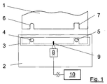
- a plate cylinder 2 shown in principle has one the printing start edge of a printing plate 1 receiving fastening device 3 in the form of a clamping rail. At the Front edge of the pressure plate 1 are spaced apart two U-shaped punchings 6, 7 arranged, which with in the fastening device 3 arranged stops 4, 5 (Register pins) interact. Define these stops 4, 5 the correct position of the pressure plate 1 on the Plate cylinder 2.
- the fastening device 3 of the plate cylinder 2 assigned a displacement sensor 8, through which the position of the Printing plate front edge within the fastening device 3 is detectable.
- the measuring range 9, within which the position the pressure plate leading edge in the fastening device 3 is detectable is shown in Figure 1.
- the displacement sensor 8 can be arranged in the plate cylinder 2 or according to a preferred embodiment of the invention outside of Plate cylinder 2.
- An evaluation unit 10 is in position with the displacement sensor 8 Signal connection in which the travel time signals of the travel sensor 8 in the manner explained further below be evaluated.
- Figure 2 shows a section through the designed as a clamping rail Fastening device 3 for the pressure start edge the pressure plate 1.
- the front edge of the pressure plate 1 is in introduced a detection area 11 formed as a gap. This detection area 11 is by moving to close a component where through the pressure plate 1 is clamped.
- a recess 12 of the fastening device 3 is a perpendicular to the plane of the pressure plate 1 and thus also to Feeding direction of the pressure plate 1 extending stylus 13 arranged.
- This stylus 13 is by not shown Means movable in the feed direction of the pressure plate 1 (arrow) and resilient (spring 14). The stylus 13 extends in the radial direction of that not shown in Figure 2 Plate cylinder 1.
- FIG. 2 is through the recess 12 from the fastening device 3 led out end of the stylus 13th a displacement sensor 8 is assigned.
- the end of the stylus 13 has a pernament magnet 15, which is accordingly Displacement sensor 8 as the location of this permanent magnet 15 within a predetermined measuring range 9 (FIG. 1) Sensor trained.
- the displacement sensor 8 can - as already mentioned - on the plate cylinder attached and thus pernament of the fastening device 3 in addition to the stylus 13.
- Prefers The invention is designed when the displacement transducer 8 is tested is hung and only in the for changing position of the plate cylinder provided by printing plates 2 employed on this and the fastening device 3 becomes. By means not shown in the figures causes the transducer 8 a predetermined distance and orientation with regard to the fastening device 3 and occupies the stylus 13 attached therein.
- the evaluation unit 10 connected to the displacement sensor 8 there is an analysis of the travel time signal of the travel sensor 8 regarding its temporal behavior. As long as the pressure plate 1 is still fed and with the punched 6, 7th does not abut the stops 4, 5 ( Figure 1), changed the path signal S with time t ( Figure 3). The steepness of the travel time signal S, t depends on the feed rate the printing plate 1. Once the leading edge of the Pressure plate 1 with the punched holes 6, 7 at the stops 4, 5 is present, the path signal S changes with respect to the time t no more. Through the evaluation unit 10 is now within a predetermined time period T checked whether the path signal S changes within this time period T.
- the evaluation unit 10 generates a corresponding output signal, what to display and / or Control of the fastening device 3 can be used can.
Landscapes
- Inking, Control Or Cleaning Of Printing Machines (AREA)
- Supply, Installation And Extraction Of Printed Sheets Or Plates (AREA)
- Rotary Presses (AREA)
Abstract
Description
- Fig. 1
- die Anordnung des erfindungsgemäßen Wegaufnehmers in einer Darstellung von oben,
- Fig. 2
- die Anordnung des Taststiftes in der Befestigungsvorrichtung sowie dessen Zusammenwirken mit dem Wegaufnehmer und
- Fig. 3
- die Auswertung der Weg- Zeitsignale des Wegaufnehmers.
- 1
- Druckplatte
- 2
- Plattenzylinder
- 3
- Befestigungsvorrichtung (Klemmschiene)
- 4
- Anschlag (Registerstift)
- 5
- Anschlag (Registerstift)
- 6
- Stanzung
- 7
- Stanzung
- 8
- Wegaufnehmer (Sensor)
- 9
- Meßbereich (Wegaufnehmer 8)
- 10
- Auswertereinheit
- 11
- Erfassungsbereich (Klemmspalt)
- 12
- Ausnehmung
- 13
- Taststift
- 14
- Feder
- 15
- Pernamentmagnet (Taststift 13)
- S
- Wegsignal (Wegaufnehmer 8)
- t
- Zeit
- T
- vorgegebene Zeitspanne
Claims (7)
- Einrichtung zur Kontrolle der Lage von Druckplatten auf dem Plattenzylinder von Druckmaschinen, insbesondere Bogenoffsetdruckmaschinen, mit einer den Druckanfang der Druckplatte aufnehmenden Befestigungsvorrichtung, wobei an der Druckanfang-Kante der Druckplatte eine mit einem Anschlag am Plattenzylinder zusammenwirkende U-förmige Ausstanzung angebracht ist und mit einem die Position der Druckplattenkante erfasssenden Wegaufnehmer,
dadurch gekennzeichnet,
daß dem Wegaufnehmer (8) ein die Lage der Vorderkante der Druckplatte (1) in der Befestigungsvorrichtung (3) hinsichtlich der Zeit wiedergebendes Weg- Zeitsignal (S, t) entnehmbar ist, und daß dem Wegaufnehmer (8) eine Auswertereinheit (10) nachgeschaltet ist, durch welche die zeitliche Änderung des Signals (S) des Wegaufnehmers (8) ermittelbar ist. - Einrichtung nach Anspruch 1,
dadurch gekennzeichnet,
daß durch den Wegaufnehmer (8) die Lage der Vorderkante der Druckplatte (1) innerhalb eines Meßbereiches (9) vorgegebener Größe erfaßbar ist. - Einrichtung nach Anspruch 1 oder 2,
dadurch gekennzeichnet,
daß der Wegaufnehmer (8) als ein berührungslos die Lage der Kante der Druckplatte (1) erfaßender Sensor ist. - Einrichtung nach Anspruch 1 oder 2
dadurch gekennzeichnet,
daß in der Befestigungsvorrichtung (3) ein durch die Kante der Druckplatte (1) auslenkbarer, senkrecht zur Zuführrichtung der Druckplatte sich erstreckender Taststift (13) angeordnet ist, dessen Position durch den Wegaufnehmer (8) erfaßbar ist. - Einrichtung nach einem der vorhergehenden Ansprüche,
dadurch gekennzeichnet,
daß der Wegaufnehmer (8) im Plattenzylinder (2) angeordnet ist. - Einrichtung nach einem der Ansprüche 1 - 4,
dadurch gekennzeichnet,
daß der Wegaufnehmer (8) außerhalb des Plattenzylinders (2) gestellfest aufgehängt und in einer zum Zuführen der neuen Druckplatte (1) zum Plattenzylinder (2) vorgesehenen Stellung anstellbar ist. - Einrichtung nach Anspruch 4,
dadurch gekennzeichnet,
daß der Taststift (13) an einem Ende einen Pernamentmagneten (15) aufweist und der Wegaufnehmer (8) ein die Position des Pernamentmagneten (15) erfassender Sensor ist.
Applications Claiming Priority (2)
| Application Number | Priority Date | Filing Date | Title |
|---|---|---|---|
| DE29907121U DE29907121U1 (de) | 1999-04-22 | 1999-04-22 | Einrichtung zur Kontrolle der Lage von Druckplatten auf dem Plattenzylinder von Druckmaschinen |
| DE29907121U | 1999-04-22 |
Publications (2)
| Publication Number | Publication Date |
|---|---|
| EP1052095A1 true EP1052095A1 (de) | 2000-11-15 |
| EP1052095B1 EP1052095B1 (de) | 2007-05-30 |
Family
ID=8072536
Family Applications (1)
| Application Number | Title | Priority Date | Filing Date |
|---|---|---|---|
| EP00107764A Expired - Lifetime EP1052095B1 (de) | 1999-04-22 | 2000-04-11 | Einrichtung zur Kontrolle der Lage von Druckplatten auf dem Plattenzylinder von Druckmaschinen |
Country Status (3)
| Country | Link |
|---|---|
| EP (1) | EP1052095B1 (de) |
| AT (1) | ATE363395T1 (de) |
| DE (2) | DE29907121U1 (de) |
Cited By (1)
| Publication number | Priority date | Publication date | Assignee | Title |
|---|---|---|---|---|
| US7730836B2 (en) | 2007-02-09 | 2010-06-08 | Heidelberger Druckmaschinen Ag | Method of aligning a printing plate against a stop |
Citations (3)
| Publication number | Priority date | Publication date | Assignee | Title |
|---|---|---|---|---|
| EP0075900A1 (de) * | 1981-09-30 | 1983-04-06 | grapho metronic Mess- und Regeltechnik GmbH & Co. KG | Vorrichtung zur Kontrolle des registergenauen Aufspannens von Druckplatten auf dem Plattenzylinder einer Offset-Druckmaschine |
| US5497703A (en) * | 1993-02-27 | 1996-03-12 | Heidelberger Druckmaschinen Ag | Device for adjusting the oblique register in a clamping device for locking printing plates in an offset printing machine |
| EP0581212B1 (de) * | 1992-07-31 | 1997-03-19 | Komori Corporation | Vorrichtung zum Montieren einer Druckplatte für eine Druckpresse |
-
1999
- 1999-04-22 DE DE29907121U patent/DE29907121U1/de not_active Expired - Lifetime
-
2000
- 2000-04-11 EP EP00107764A patent/EP1052095B1/de not_active Expired - Lifetime
- 2000-04-11 AT AT00107764T patent/ATE363395T1/de not_active IP Right Cessation
- 2000-04-11 DE DE50014359T patent/DE50014359D1/de not_active Expired - Lifetime
Patent Citations (3)
| Publication number | Priority date | Publication date | Assignee | Title |
|---|---|---|---|---|
| EP0075900A1 (de) * | 1981-09-30 | 1983-04-06 | grapho metronic Mess- und Regeltechnik GmbH & Co. KG | Vorrichtung zur Kontrolle des registergenauen Aufspannens von Druckplatten auf dem Plattenzylinder einer Offset-Druckmaschine |
| EP0581212B1 (de) * | 1992-07-31 | 1997-03-19 | Komori Corporation | Vorrichtung zum Montieren einer Druckplatte für eine Druckpresse |
| US5497703A (en) * | 1993-02-27 | 1996-03-12 | Heidelberger Druckmaschinen Ag | Device for adjusting the oblique register in a clamping device for locking printing plates in an offset printing machine |
Cited By (1)
| Publication number | Priority date | Publication date | Assignee | Title |
|---|---|---|---|---|
| US7730836B2 (en) | 2007-02-09 | 2010-06-08 | Heidelberger Druckmaschinen Ag | Method of aligning a printing plate against a stop |
Also Published As
| Publication number | Publication date |
|---|---|
| DE29907121U1 (de) | 1999-07-01 |
| DE50014359D1 (de) | 2007-07-12 |
| EP1052095B1 (de) | 2007-05-30 |
| ATE363395T1 (de) | 2007-06-15 |
Similar Documents
| Publication | Publication Date | Title |
|---|---|---|
| EP1452827B1 (de) | Vorrichtung mit einem in einem Rohr bewegbaren Molch und einem Positionsdetektor für den Molch | |
| DE10241904B9 (de) | Sensor für Königszapfen | |
| EP0582903B1 (de) | Vorrichtung zur Kontrolle der registergerechten Anlage einer Druckplatte auf dem Plattenzylinder von Druckmaschinen, insbesondere Bogenoffsetdruckmaschinen | |
| EP1649250B1 (de) | Vorrichtung und verfahren zur erfassung des wegs eines zielobjekts | |
| EP2166312B2 (de) | Magnetischer oder induktiver Wegsensor | |
| EP0819913A1 (de) | Verfahren und Vorrichtung zur Positionierung von nicht-geradlinigen bewegten insbesondere rotierenden Maschinenteilen | |
| EP3663722B1 (de) | Verfahren zur automatischen kalibrierung eines magnetischen sensors und magnetischer sensor | |
| DE19712829B4 (de) | Vorrichtung zur Erkennung der Position eines beweglichen Gegenstandes | |
| DE102021107898A1 (de) | Kettenlängungsüberwachungsvorrichtung und verfahren zur ermittlung des verschleisses | |
| EP1052095B1 (de) | Einrichtung zur Kontrolle der Lage von Druckplatten auf dem Plattenzylinder von Druckmaschinen | |
| EP3976439B1 (de) | Sensoreinrichtung für eine anordnung zur detektion und analyse eines entlang einer spur, insbesondere entlang eines gleises, bewegten rades eines fahrzeugs | |
| EP0651231A1 (de) | Verfahren und Vorrichtung zur Messung der Dicke von Druckereierzeugnissen, wie Zeitungen, Zeitschriften und Teilen hiervon | |
| DE2520851C3 (de) | Vorrichtung zur Erfassung der Einwirkung eines sich bewegenden Elements auf ein Abgriffsystem | |
| EP3156528A1 (de) | Textilmaschine mit einem entlang der arbeitsstellen verfahrbaren serviceaggregat und verfahren zur positionierung eines serviceaggregats vor einer arbeitsstelle | |
| EP4190436B1 (de) | Industrielle mischmaschine | |
| DE3522809C2 (de) | ||
| EP0966653A1 (de) | Vorrichtung zur positionserfassung eines beweglich angeordneten magneten zum erzeugen eines magnetischen feldes | |
| DE19756475A1 (de) | Bedienhebel und Verfahren zum Betreiben des Bedienhebels | |
| EP0490266B1 (de) | Annäherungsschalter | |
| EP1046502B1 (de) | Einrichtung zur Kontrolle der registerechten Anlage von Druckplatten | |
| EP3674035B1 (de) | Spannvorrichtung mit induktiver abfrageeinheit | |
| EP1046503B1 (de) | Einrichtung zur Kontrolle der Lage von Druckplatten | |
| DE60034471T2 (de) | Elektronisches lenksäulenmodul | |
| DE4318220C2 (de) | Vorrichtung zur Bogenlängenerkennung an Bogendruckmaschinen | |
| DE202021106467U1 (de) | Stellventileinheit mit einem Ventilgehäuse |
Legal Events
| Date | Code | Title | Description |
|---|---|---|---|
| PUAI | Public reference made under article 153(3) epc to a published international application that has entered the european phase |
Free format text: ORIGINAL CODE: 0009012 |
|
| 17P | Request for examination filed |
Effective date: 20000812 |
|
| AK | Designated contracting states |
Kind code of ref document: A1 Designated state(s): AT BE CH CY DE DK ES FI FR GB GR IE IT LI LU MC NL PT SE |
|
| AX | Request for extension of the european patent |
Free format text: AL;LT;LV;MK;RO;SI |
|
| AKX | Designation fees paid |
Free format text: AT BE CH CY DE DK ES FI FR GB GR IE IT LI LU MC NL PT SE |
|
| GRAP | Despatch of communication of intention to grant a patent |
Free format text: ORIGINAL CODE: EPIDOSNIGR1 |
|
| GRAS | Grant fee paid |
Free format text: ORIGINAL CODE: EPIDOSNIGR3 |
|
| GRAA | (expected) grant |
Free format text: ORIGINAL CODE: 0009210 |
|
| AK | Designated contracting states |
Kind code of ref document: B1 Designated state(s): AT BE CH CY DE DK ES FI FR GB GR IE IT LI LU MC NL PT SE |
|
| PG25 | Lapsed in a contracting state [announced via postgrant information from national office to epo] |
Ref country code: FI Free format text: LAPSE BECAUSE OF FAILURE TO SUBMIT A TRANSLATION OF THE DESCRIPTION OR TO PAY THE FEE WITHIN THE PRESCRIBED TIME-LIMIT Effective date: 20070530 |
|
| REG | Reference to a national code |
Ref country code: GB Ref legal event code: FG4D Free format text: NOT ENGLISH |
|
| REG | Reference to a national code |
Ref country code: CH Ref legal event code: EP |
|
| REG | Reference to a national code |
Ref country code: IE Ref legal event code: FG4D Free format text: LANGUAGE OF EP DOCUMENT: GERMAN |
|
| REF | Corresponds to: |
Ref document number: 50014359 Country of ref document: DE Date of ref document: 20070712 Kind code of ref document: P |
|
| PG25 | Lapsed in a contracting state [announced via postgrant information from national office to epo] |
Ref country code: SE Free format text: LAPSE BECAUSE OF FAILURE TO SUBMIT A TRANSLATION OF THE DESCRIPTION OR TO PAY THE FEE WITHIN THE PRESCRIBED TIME-LIMIT Effective date: 20070830 |
|
| PG25 | Lapsed in a contracting state [announced via postgrant information from national office to epo] |
Ref country code: ES Free format text: LAPSE BECAUSE OF FAILURE TO SUBMIT A TRANSLATION OF THE DESCRIPTION OR TO PAY THE FEE WITHIN THE PRESCRIBED TIME-LIMIT Effective date: 20070910 |
|
| ET | Fr: translation filed | ||
| NLV1 | Nl: lapsed or annulled due to failure to fulfill the requirements of art. 29p and 29m of the patents act | ||
| GBV | Gb: ep patent (uk) treated as always having been void in accordance with gb section 77(7)/1977 [no translation filed] |
Effective date: 20070530 |
|
| REG | Reference to a national code |
Ref country code: IE Ref legal event code: FD4D |
|
| PG25 | Lapsed in a contracting state [announced via postgrant information from national office to epo] |
Ref country code: IE Free format text: LAPSE BECAUSE OF FAILURE TO SUBMIT A TRANSLATION OF THE DESCRIPTION OR TO PAY THE FEE WITHIN THE PRESCRIBED TIME-LIMIT Effective date: 20070530 Ref country code: DK Free format text: LAPSE BECAUSE OF FAILURE TO SUBMIT A TRANSLATION OF THE DESCRIPTION OR TO PAY THE FEE WITHIN THE PRESCRIBED TIME-LIMIT Effective date: 20070530 Ref country code: NL Free format text: LAPSE BECAUSE OF FAILURE TO SUBMIT A TRANSLATION OF THE DESCRIPTION OR TO PAY THE FEE WITHIN THE PRESCRIBED TIME-LIMIT Effective date: 20070530 Ref country code: PT Free format text: LAPSE BECAUSE OF FAILURE TO SUBMIT A TRANSLATION OF THE DESCRIPTION OR TO PAY THE FEE WITHIN THE PRESCRIBED TIME-LIMIT Effective date: 20071030 |
|
| PLBE | No opposition filed within time limit |
Free format text: ORIGINAL CODE: 0009261 |
|
| STAA | Information on the status of an ep patent application or granted ep patent |
Free format text: STATUS: NO OPPOSITION FILED WITHIN TIME LIMIT |
|
| PG25 | Lapsed in a contracting state [announced via postgrant information from national office to epo] |
Ref country code: IT Free format text: LAPSE BECAUSE OF FAILURE TO SUBMIT A TRANSLATION OF THE DESCRIPTION OR TO PAY THE FEE WITHIN THE PRESCRIBED TIME-LIMIT Effective date: 20070530 Ref country code: GB Free format text: LAPSE BECAUSE OF FAILURE TO SUBMIT A TRANSLATION OF THE DESCRIPTION OR TO PAY THE FEE WITHIN THE PRESCRIBED TIME-LIMIT Effective date: 20070530 Ref country code: GR Free format text: LAPSE BECAUSE OF FAILURE TO SUBMIT A TRANSLATION OF THE DESCRIPTION OR TO PAY THE FEE WITHIN THE PRESCRIBED TIME-LIMIT Effective date: 20070831 |
|
| 26N | No opposition filed |
Effective date: 20080303 |
|
| BERE | Be: lapsed |
Owner name: MAN ROLAND DRUCKMASCHINEN A.G. Effective date: 20080430 |
|
| PG25 | Lapsed in a contracting state [announced via postgrant information from national office to epo] |
Ref country code: MC Free format text: LAPSE BECAUSE OF NON-PAYMENT OF DUE FEES Effective date: 20080430 |
|
| REG | Reference to a national code |
Ref country code: CH Ref legal event code: PL |
|
| PG25 | Lapsed in a contracting state [announced via postgrant information from national office to epo] |
Ref country code: LI Free format text: LAPSE BECAUSE OF NON-PAYMENT OF DUE FEES Effective date: 20080430 Ref country code: CH Free format text: LAPSE BECAUSE OF NON-PAYMENT OF DUE FEES Effective date: 20080430 |
|
| PG25 | Lapsed in a contracting state [announced via postgrant information from national office to epo] |
Ref country code: BE Free format text: LAPSE BECAUSE OF NON-PAYMENT OF DUE FEES Effective date: 20080430 |
|
| REG | Reference to a national code |
Ref country code: FR Ref legal event code: CD |
|
| PG25 | Lapsed in a contracting state [announced via postgrant information from national office to epo] |
Ref country code: CY Free format text: LAPSE BECAUSE OF FAILURE TO SUBMIT A TRANSLATION OF THE DESCRIPTION OR TO PAY THE FEE WITHIN THE PRESCRIBED TIME-LIMIT Effective date: 20070530 |
|
| PG25 | Lapsed in a contracting state [announced via postgrant information from national office to epo] |
Ref country code: LU Free format text: LAPSE BECAUSE OF NON-PAYMENT OF DUE FEES Effective date: 20080411 |
|
| PGFP | Annual fee paid to national office [announced via postgrant information from national office to epo] |
Ref country code: FR Payment date: 20100506 Year of fee payment: 11 |
|
| PGFP | Annual fee paid to national office [announced via postgrant information from national office to epo] |
Ref country code: AT Payment date: 20100415 Year of fee payment: 11 |
|
| PGFP | Annual fee paid to national office [announced via postgrant information from national office to epo] |
Ref country code: DE Payment date: 20110421 Year of fee payment: 12 |
|
| REG | Reference to a national code |
Ref country code: AT Ref legal event code: MM01 Ref document number: 363395 Country of ref document: AT Kind code of ref document: T Effective date: 20110411 |
|
| REG | Reference to a national code |
Ref country code: FR Ref legal event code: ST Effective date: 20111230 |
|
| PG25 | Lapsed in a contracting state [announced via postgrant information from national office to epo] |
Ref country code: FR Free format text: LAPSE BECAUSE OF NON-PAYMENT OF DUE FEES Effective date: 20110502 |
|
| PG25 | Lapsed in a contracting state [announced via postgrant information from national office to epo] |
Ref country code: AT Free format text: LAPSE BECAUSE OF NON-PAYMENT OF DUE FEES Effective date: 20110411 |
|
| REG | Reference to a national code |
Ref country code: DE Ref legal event code: R081 Ref document number: 50014359 Country of ref document: DE Owner name: MANROLAND SHEETFED GMBH, DE Free format text: FORMER OWNER: MANROLAND AG, 63075 OFFENBACH, DE Effective date: 20120509 |
|
| REG | Reference to a national code |
Ref country code: DE Ref legal event code: R119 Ref document number: 50014359 Country of ref document: DE Effective date: 20121101 |
|
| PG25 | Lapsed in a contracting state [announced via postgrant information from national office to epo] |
Ref country code: DE Free format text: LAPSE BECAUSE OF NON-PAYMENT OF DUE FEES Effective date: 20121101 |