EP1052013A1 - Macroporous support having a permeability gradient and method for its production - Google Patents
Macroporous support having a permeability gradient and method for its production Download PDFInfo
- Publication number
- EP1052013A1 EP1052013A1 EP00119122A EP00119122A EP1052013A1 EP 1052013 A1 EP1052013 A1 EP 1052013A1 EP 00119122 A EP00119122 A EP 00119122A EP 00119122 A EP00119122 A EP 00119122A EP 1052013 A1 EP1052013 A1 EP 1052013A1
- Authority
- EP
- European Patent Office
- Prior art keywords
- support
- macroporous
- porosity
- gradient
- flow
- Prior art date
- Legal status (The legal status is an assumption and is not a legal conclusion. Google has not performed a legal analysis and makes no representation as to the accuracy of the status listed.)
- Withdrawn
Links
- 230000035699 permeability Effects 0.000 title claims abstract description 17
- 238000000034 method Methods 0.000 title claims description 24
- 238000004519 manufacturing process Methods 0.000 title abstract description 9
- 238000005470 impregnation Methods 0.000 claims abstract description 30
- 239000007788 liquid Substances 0.000 claims abstract description 30
- 239000011148 porous material Substances 0.000 claims abstract description 30
- 239000012528 membrane Substances 0.000 claims abstract description 28
- 239000000463 material Substances 0.000 claims abstract description 22
- 239000012530 fluid Substances 0.000 claims abstract description 14
- XLYOFNOQVPJJNP-UHFFFAOYSA-N water Substances O XLYOFNOQVPJJNP-UHFFFAOYSA-N 0.000 claims abstract description 12
- 239000007921 spray Substances 0.000 claims abstract description 11
- 238000005507 spraying Methods 0.000 claims abstract description 9
- 238000006073 displacement reaction Methods 0.000 claims abstract description 7
- 229920006395 saturated elastomer Polymers 0.000 claims abstract description 6
- 238000001914 filtration Methods 0.000 claims description 27
- 238000002360 preparation method Methods 0.000 claims description 11
- 238000007654 immersion Methods 0.000 claims description 6
- 239000000243 solution Substances 0.000 claims 3
- 238000002347 injection Methods 0.000 claims 1
- 239000007924 injection Substances 0.000 claims 1
- 239000012466 permeate Substances 0.000 description 21
- 239000011347 resin Substances 0.000 description 12
- 229920005989 resin Polymers 0.000 description 12
- 230000008569 process Effects 0.000 description 9
- 239000000919 ceramic Substances 0.000 description 8
- 238000005245 sintering Methods 0.000 description 8
- 239000000203 mixture Substances 0.000 description 7
- PNEYBMLMFCGWSK-UHFFFAOYSA-N aluminium oxide Inorganic materials [O-2].[O-2].[O-2].[Al+3].[Al+3] PNEYBMLMFCGWSK-UHFFFAOYSA-N 0.000 description 5
- 238000005520 cutting process Methods 0.000 description 5
- 230000035515 penetration Effects 0.000 description 5
- 238000002791 soaking Methods 0.000 description 5
- 229910010293 ceramic material Inorganic materials 0.000 description 4
- QSHDDOUJBYECFT-UHFFFAOYSA-N mercury Chemical compound [Hg] QSHDDOUJBYECFT-UHFFFAOYSA-N 0.000 description 4
- 229910052753 mercury Inorganic materials 0.000 description 4
- 239000002245 particle Substances 0.000 description 4
- 238000002459 porosimetry Methods 0.000 description 4
- 230000000750 progressive effect Effects 0.000 description 4
- ZWEHNKRNPOVVGH-UHFFFAOYSA-N 2-Butanone Chemical compound CCC(C)=O ZWEHNKRNPOVVGH-UHFFFAOYSA-N 0.000 description 3
- 238000007664 blowing Methods 0.000 description 3
- 238000004132 cross linking Methods 0.000 description 3
- 230000003247 decreasing effect Effects 0.000 description 3
- 239000004810 polytetrafluoroethylene Substances 0.000 description 3
- 229920001343 polytetrafluoroethylene Polymers 0.000 description 3
- 239000000843 powder Substances 0.000 description 3
- RTZKZFJDLAIYFH-UHFFFAOYSA-N Diethyl ether Chemical compound CCOCC RTZKZFJDLAIYFH-UHFFFAOYSA-N 0.000 description 2
- LFQSCWFLJHTTHZ-UHFFFAOYSA-N Ethanol Chemical compound CCO LFQSCWFLJHTTHZ-UHFFFAOYSA-N 0.000 description 2
- MCMNRKCIXSYSNV-UHFFFAOYSA-N Zirconium dioxide Chemical compound O=[Zr]=O MCMNRKCIXSYSNV-UHFFFAOYSA-N 0.000 description 2
- 239000007900 aqueous suspension Substances 0.000 description 2
- 239000003822 epoxy resin Substances 0.000 description 2
- 238000000227 grinding Methods 0.000 description 2
- 229910052500 inorganic mineral Inorganic materials 0.000 description 2
- 239000011707 mineral Substances 0.000 description 2
- 229920000647 polyepoxide Polymers 0.000 description 2
- 239000004848 polyfunctional curative Substances 0.000 description 2
- 239000002904 solvent Substances 0.000 description 2
- 239000000725 suspension Substances 0.000 description 2
- GEYOCULIXLDCMW-UHFFFAOYSA-N 1,2-phenylenediamine Chemical compound NC1=CC=CC=C1N GEYOCULIXLDCMW-UHFFFAOYSA-N 0.000 description 1
- KUBDPQJOLOUJRM-UHFFFAOYSA-N 2-(chloromethyl)oxirane;4-[2-(4-hydroxyphenyl)propan-2-yl]phenol Chemical compound ClCC1CO1.C=1C=C(O)C=CC=1C(C)(C)C1=CC=C(O)C=C1 KUBDPQJOLOUJRM-UHFFFAOYSA-N 0.000 description 1
- OKTJSMMVPCPJKN-UHFFFAOYSA-N Carbon Chemical compound [C] OKTJSMMVPCPJKN-UHFFFAOYSA-N 0.000 description 1
- 235000014066 European mistletoe Nutrition 0.000 description 1
- 235000012300 Rhipsalis cassutha Nutrition 0.000 description 1
- 229920002125 Sokalan® Polymers 0.000 description 1
- 241000221012 Viscum Species 0.000 description 1
- 239000002253 acid Substances 0.000 description 1
- 230000006978 adaptation Effects 0.000 description 1
- 239000011324 bead Substances 0.000 description 1
- 230000008901 benefit Effects 0.000 description 1
- 230000033228 biological regulation Effects 0.000 description 1
- 229910052799 carbon Inorganic materials 0.000 description 1
- 239000003054 catalyst Substances 0.000 description 1
- 230000008859 change Effects 0.000 description 1
- 238000006243 chemical reaction Methods 0.000 description 1
- 239000003795 chemical substances by application Substances 0.000 description 1
- 239000012141 concentrate Substances 0.000 description 1
- 238000005260 corrosion Methods 0.000 description 1
- 230000007797 corrosion Effects 0.000 description 1
- 238000005336 cracking Methods 0.000 description 1
- 238000007598 dipping method Methods 0.000 description 1
- 238000001035 drying Methods 0.000 description 1
- 230000008030 elimination Effects 0.000 description 1
- 238000003379 elimination reaction Methods 0.000 description 1
- 238000005516 engineering process Methods 0.000 description 1
- 238000000605 extraction Methods 0.000 description 1
- 238000001125 extrusion Methods 0.000 description 1
- 238000011049 filling Methods 0.000 description 1
- 210000001061 forehead Anatomy 0.000 description 1
- 239000011521 glass Substances 0.000 description 1
- 239000008187 granular material Substances 0.000 description 1
- 239000012510 hollow fiber Substances 0.000 description 1
- 239000008240 homogeneous mixture Substances 0.000 description 1
- 230000014759 maintenance of location Effects 0.000 description 1
- 238000005374 membrane filtration Methods 0.000 description 1
- 229910052751 metal Inorganic materials 0.000 description 1
- 239000002184 metal Substances 0.000 description 1
- 230000005012 migration Effects 0.000 description 1
- 238000013508 migration Methods 0.000 description 1
- 230000004048 modification Effects 0.000 description 1
- 238000012986 modification Methods 0.000 description 1
- 239000011368 organic material Substances 0.000 description 1
- 239000004584 polyacrylic acid Substances 0.000 description 1
- 229920000642 polymer Polymers 0.000 description 1
- 238000000079 presaturation Methods 0.000 description 1
- 238000012545 processing Methods 0.000 description 1
- 230000001954 sterilising effect Effects 0.000 description 1
- 238000004659 sterilization and disinfection Methods 0.000 description 1
- 238000003756 stirring Methods 0.000 description 1
- 239000000126 substance Substances 0.000 description 1
- 230000007704 transition Effects 0.000 description 1
- 238000013519 translation Methods 0.000 description 1
- 238000011144 upstream manufacturing Methods 0.000 description 1
Images
Classifications
-
- B—PERFORMING OPERATIONS; TRANSPORTING
- B01—PHYSICAL OR CHEMICAL PROCESSES OR APPARATUS IN GENERAL
- B01D—SEPARATION
- B01D69/00—Semi-permeable membranes for separation processes or apparatus characterised by their form, structure or properties; Manufacturing processes specially adapted therefor
- B01D69/10—Supported membranes; Membrane supports
- B01D69/107—Organic support material
-
- B—PERFORMING OPERATIONS; TRANSPORTING
- B01—PHYSICAL OR CHEMICAL PROCESSES OR APPARATUS IN GENERAL
- B01D—SEPARATION
- B01D69/00—Semi-permeable membranes for separation processes or apparatus characterised by their form, structure or properties; Manufacturing processes specially adapted therefor
- B01D69/10—Supported membranes; Membrane supports
-
- B—PERFORMING OPERATIONS; TRANSPORTING
- B01—PHYSICAL OR CHEMICAL PROCESSES OR APPARATUS IN GENERAL
- B01D—SEPARATION
- B01D63/00—Apparatus in general for separation processes using semi-permeable membranes
- B01D63/06—Tubular membrane modules
- B01D63/066—Tubular membrane modules with a porous block having membrane coated passages
Definitions
- the present invention relates to a macroporous support which has a permeability gradient along the flow of the fluid to be treated, as well as its process Manufacturing.
- the invention relates in particular to such a macroporous support in sintered ceramic material, sintered glass, sintered metal or carbon, pierced with a or several longitudinal and parallel channels, and of which the surface of said channels is covered with one or several filter layers of ceramic material sintered or organic, in which a liquid circulates purify or concentrate, or generally a fluid to treat.
- the macroporous support and layer assembly filter is called below membrane.
- the fluid to be treated arrives by an entry chamber at an entry end of the porous support or (macro) block, flows in the channels to an outlet end, to a exit; a fraction of liquid to be treated or permeate radially crosses the layer and the macroporous support, before being collected in the outlet side chamber permeate.
- the liquid to be treated circulates along the channel (s), and this flow induces a pressure drop between the inlet and the output of said channels.
- This pressure drop depends of a set of parameters such as for example the speed of the liquid to be treated or purified in the canal, the viscosity of said liquid, as well as the diameter hydraulic channel.
- This decreasing variation in pressure of the liquid to be treated along the channel (s) modifies the transverse flow of permeate which crosses the filter layer and then the macroporous body.
- the inlet pressure in the channels is 3.8 bars
- the outlet pressure of the channels is 2 bars
- the pressure in the permeate outlet chamber is constant for example 1.5 bars.
- the transverse pressure drop varies the along the membrane from 2.3 to 0.5 bars.
- US-P-4,105,547 describes a device for tangential filtration using a additional compensation for the longitudinal pressure drop.
- Said additional system consists in that the surface outside of the support side of the permeate, is swept by the permeate which circulates in the same direction as the liquid to process so as to create in the permeate chamber a longitudinal pressure drop such as the loss of transverse load remains approximately constant the along the filter.
- Patent EP-A-0 333 753 describes a method of realization of this device which compensates this induced transverse pressure drop variation by the circulation of a liquid inside one or multiple channels.
- the said system consists in the establishment of a permeate circulation on the exterior surface of a tubular membrane, a porous support pierced with a channel or a porous block also pierced with one or multiple channels.
- Such filter media can be assembled individually or in bundles in a housing where the permeate chamber is filled with filling bodies such as beads or granules which induce resistance to the longitudinal flow of the permeate which is of a nature to offset the variation in pressure drop longitudinal induced by the circulation of the liquid at treat in the channel (s) covered with a layer of filtration.
- the invention therefore aims to provide a device simple tangential filtration requires no adaptation of existing equipment and no additional energy costs.
- the invention provides a macroporous support for tangential filtration with a gradient of permeability according to the direction of flow of the fluid at treat.
- the invention also provides a macroporous support for tangential filtration with a gradient of average porosity on the belt depending on the direction of flow of the fluid to be treated, the average porosity increasing in said direction of flow.
- the porosity gradient mean corresponds to an impregnation gradient from of the external surface of said support.
- the diameter of the pore of the impregnated area is between 0.1 and 0.8 times the pore diameter of the unimpregnated area, preferably between 0.3 and 0.5.
- the porosity ratio average output / average porosity included between 1.1 and 4.
- the level of initial porosity is between 15 and 45%.
- the invention also provides a membrane comprising a macroporous support according to the invention, in combination with a filtration layer.
- the invention also provides a method of preparation a macroporous support according to the invention, comprising the step of immersion in a slip or a solution organic in a substantially vertical position of a support macroporous, the bottom end of which is blocked.
- the residence time is between 0 and 15 sec., preferably between 0.5 and 8 dry. for the least and most parts respectively submerged.
- the invention also provides a method of preparation a macroporous support according to the invention, comprising the step of spraying a slip or a organic solution on a normal macroporous support, the spray zone moving along said support.
- the speed of displacement of the spray nozzle is included between 0.1 cm / s and 3 cm / s, preferably 0.7 cm / s and 1.7 cm / s.
- the spraying material flow rate is variable along said support, the speed of displacement of the spray nozzle being constant.
- the material flow rate of spraying is constant, the moving speed of the spray nozzle being variable along said support.
- the invention also provides a method of preparation a macroporous support according to the invention, comprising the water saturation step of a macroporous support normal, then the step of injecting gas into said support whose outlet end is free, partially closed or completely closed, and the step immersion in a substantially horizontal position of said support in slip or organic solution.
- the invention also relates to a support macroporous saturated with liquid having a gradient of free volume.
- the invention provides the use of a support macroporous according to the invention, for filtration tangential.
- the invention also provides the use of a membrane according to the invention, for filtration tangential.
- macroporous support is used in its common sense to those skilled in the art, and includes in particular supports for membrane filtration including hollow fibers.
- unmodified porosity or initial designates the porosity of the macroporous support before application of the treatment according to the invention.
- Porosity represents the pore volume of the support expressed in percent volume of the support volume.
- a support "initial” is a support before applying the treatment according to the invention.
- a support "initial" macroporous has a pore diameter of more than 4 ⁇ m, typically between 4 and 50 ⁇ m.
- modified porosity designates the porosity of the support area modified by the application of treatment according to the invention.
- the average porosity of a slice transverse of given thickness of the macroporous support varies increasing in the longitudinal direction of said support, which is the direction of circulation of the liquid to be treated, so that the permeability of said support in the transverse direction varies from similarly in the longitudinal direction.
- the average porosity term means the average porosity between the modified and unmodified areas of the support macroporous.
- This permeability gradient generates a gradient longitudinal of the transverse pressure drop of the permeate through the support, which is approximately equal to the longitudinal gradient of pressure of liquid to be treated in the channel. It follows that the transverse pressure drop between inside the channel and the interface between the layer filtering and the support is approximately constant along the entire length of the membrane, allowing optimize filtration without using a related equipment.
- This permeability gradient is obtained in particular by a gradient of average porosity, which will be described more in detail below.
- the first one variant consists of impregnating the support macroporous over part of its thickness, from its outer surface.
- the impregnation front according to this variant can be sharp or diffuse.
- this variant there is then a modification of the average porosity of the support.
- Another variant consists of a deposit on the outer surface of the support permeate side of a layer decreasing thickness, the pore size of which is smaller than that of the pores of the support.
- the porosity gradient is obtained directly at the time of manufacture of the macroporous support and by example by continuously changing the load of an agent porogenic throughout the support during its extrusion by a screw extruder for example or by making the sintering of the macroporous support according to a gradient of temperature and / or for example using a transition to speed gradient.
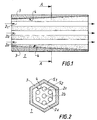
- the support according to the invention 1 comprises channels 2a, 2b and 2c, and has an area at its outer surface impregnated with a material, represented by the hatched area 3.
- the direction of flow of the liquid to be treated is indicated by the arrows.
- the front 4 is sharp; it can however be diffuse.
- FIG. 2 which is a section A-A, the same support is represented with the same references.
- the belt section corresponds to the sum of the areas S1 and S2, which are the surfaces of the sections of the zones modified and unmodified respectively.
- Forehead shown is the same as shown in figure 1.
- the support present in its longitudinal direction a gradient of medium porosity (Pm).
- Pm medium porosity
- the average porosity can be calculated as a mean between the porosity of the modified zone and the porosity of the unmodified area on the surface of the belt section. This average is defined in surface terms.
- the elements necessary to calculate the average porosity are shown in figure 2. In the figure 2, in which there is a very clear front, we can calculate the average porosity Pm as follows:
- Pm [(P1 x S1) + (P2 x S2)] / (S1 + S2) where P1 and P2 are the respective porosities of the modified area of surface S1 and of the unmodified area of surface S2.
- the device of the invention is according to a mode of realization of a macroporous block pierced with one or more channels possibly covered with a filter layer, and impregnated, from its outer side surface permeate, decreasingly in the direction of the length, at least over part of its thickness, with a mineral or organic material so as to reduce the porosity of the impregnated zone with respect to the non-zone impregnated.
- the ratio of the average porosity of the exit end of the macroporous block on the porosity mean of the input end of the macroporous block is between 1.1 and 4. This change in porosity allows to establish a pressure drop evolution transverse which is substantially equivalent to the loss longitudinal load, induced by the liquid to be treated flowing through the channel (s).
- the permeate undergoes resistance additional to the flow in the impregnated area of which the porosity is lower than in the non-zone impregnated. This constraint increases with the thickness of the impregnated area, and therefore must be larger at entry level of the fluid to be treated.
- Such a filtration device therefore imposes a sense circulation for the liquid to be treated, i.e. the end of the most impregnated porous block will be arranged on the side of the liquid inlet chamber to process, the other weakly impregnated end is it arranged on the side of the liquid outlet chamber to treat.
- the transverse pressure drop is defined by so as to obtain a filtration regime compatible with the nature of the liquid to be treated. It has therefore been adapted in advance at the speed of circulation in the fluid channels to be treated, and to the characteristics of viscosity and filtration rate of said fluid. AT the reverse to achieve filtration with a membrane given according to the invention, the speed of circulation of the liquid to be filtered in the channels so to obtain a longitudinal pressure drop gradient in the channels equal to the longitudinal gradient of loss of transverse load on the permeate.
- the porosity of the block impregnation material macroporous can be a ceramic material similarly composition than that of the macroporous block.
- the filtration device has resistance to corrosion at least as high as that of the porous block.
- the impregnation material is the same composition than that of the macroporous block, we benefit equal expansion coefficients.
- the filtration device presents no risk of cracking which may result from stresses during its manufacture, then its use with hot fluids, or steam sterilization.
- the impregnation material is obtained from a powder of the same composition and sintering temperature compatible with that from which filter layer is obtained, it is useless to perform separate sintering operations for the filter layer and impregnation material.
- the impregnation operation does not affect the sintering operations conventionally implemented for the manufacture of ceramic filtration elements.
- the impregnation material may be of the same nature as the material of the macroporous support, namely mineral and introduced into the support in the form of a suspension or slip.
- the material is of organic origin, it can be any resin and for example an epoxy resin or a polymer and for example a PTFE introduced in the form of a suspension.
- the impregnation solution or composition has a suitable viscosity, for example understood between 15-400 mPa.s, preferably 30-100 mPa.s.
- the process of manufacturing the filtration device includes the steps to prepare a deflocculated slip from a powder of a ceramic or polymeric material of which the average particle size is between 0.1 and 4 microns, viscosity suitable for this technology soaking, and the powder concentration of ceramic or polymeric material is between 2.5 and 75% by volume depending on the thickness of the block porous material that one wishes to impregnate, followed by the step of progressive soaking of the porous block whose ends channels are blocked, in this slip, of preferably by shaking it, then the sintering step impregnation material.
- the soaking time is between 0 and 15 seconds and preferably between 0.5 and 8 seconds for respectively the submerged zones during the time the shortest (which will give the most average porosity close to the initial porosity) and the areas submerged for the longest time (which will give the average porosity most different from porosity initial).
- the impregnation is carried out at one stage of the process which does not risk modifying the characteristics of membranes at the later stage of their sintering, and / or so that the following steps of the process do not degrade the characteristics of the impregnation, such as for example the permeability of the impregnated area.
- the impregnation may be only partial (in the lengthwise) in a support area macroporous.
- a gradual presaturation technique porous support which is characterized in that it is saturated the porous block with a liquid, preferably water, that we blow with compressed air in the channels from one end of the porous body, the other end may be free, partially or completely closed, in order to establish a pressure drop which is sufficient to gradually eliminate in the direction longitudinal of the porous block, the liquid contained in the porosity of said block, then in that the block is quenched porous in vertical, oblique or horizontal position in a slip made from ceramic material or polymeric as previously described.
- the slip will occupy the free pore volume which has gradually released by blowing, without the duration of stay of the porous block in the slip significantly influences the penetration of areas which should be lightly impregnated.
- This support saturated with liquid and having a cone of free volume is also an element of the invention.
- Such a manufacturing process when the material impregnation is a ceramic or polymeric material includes the use of a slip whose concentration of ceramic or polymeric material is between i and 60% by volume that we project, by example using compressed air, through a spray nozzle moved opposite the outer surface of the porous block which is in rotation along its longitudinal axis.
- the displacement of the nozzle can be progressive, i.e. at variable speed (increasing or decreasing) and constant flow, or at constant speed and variable flow. Speed and flow can also vary both at the same time.
- Another technique can also be used, which consists in using a pump upstream of the nozzle high pressure liquid.
- the removal process can consist of a homogeneous mixture of resin, required amount of hardener and thinner which lowers the viscosity of said mixture, then in that one projects the preparation via a nozzle spray which is moved gradually in look at the surface of the porous block which is located even in rotation along its longitudinal axis and in this that the temperature crosslinking of the resin.
- the temperature cycle is defined among other things by so as to favor the lowering of viscosity, in order to facilitate the migration of the resin in the porosity of the block so as to only partially block porosity of the block.
- An aqueous alumina slip is prepared, with an average particle diameter of 0.4 micron, that we deflocculate with a polyacrylic acid such as DARVAN C® then grinding in a jar.
- this slip consists of: Alumina AES-11 43% DARVAN C® 3.3% Water 53.7% Viscosity 70 mPas.
- the macroporous support or block has a length of 1020 mm, and is drilled with 19 channels of 4 mm diameter, allowing to define a 2 mm belt large. It is characterized by an initial porosity of 33 % and an initial pore diameter of 12 ⁇ m.
- a soaking device including a clamp holding the support firmly macroporous in vertical position, a guide rail for the gripper controlled by a servomotor, plugs semipermeable to seal the support channels macroporous.
- the clamp gradually immerses the support macroporous in the slip contained in a tank of which the bottom is equipped with a stirring device for the slip suitable for holding the aqueous suspension homogeneous.
- the holding clamp is controlled until immersion total in the support bath then extraction.
- the pilot programming is such that the linear speed of displacement of the support is substantially constant in absolute value, about 25.5 cm / s, so the time of stay of the party that is the shortest time in contact with the slip is about 0.5 s, while the time for stay for the longest part in contact with the slip is about 8 s.
- the porosity of the impregnated area is 8% while that of the non-impregnated zone (initial porosity) is 33%.
- the average porosity, along the support, calculated on the belt varies from 30.5 to 10.5, a ratio input - output of 2.9.
- the pore diameter of the area modified measured by mercury porosimetry is 4 ⁇ m, or 0.33 times the initial pore diameter.
- a modified support such as that described in example i a zirconia filtration layer with a pore diameter of 0.1 ⁇ m.
- the transverse water permeability is measured by applying a pressure difference between the channels and the external surface of 1 bar. This gives a flow rate of 1.5 l / H (i.e. a permeability of 640 l / Hm 2 bar) for the inlet section of the membrane and a flow rate of 4.7 l / Hm 2 bar (i.e. a permeability of 2000 l / Hm 2 bar) for the outlet section.
- the ratio of the transverse permeabilities of the two sections is therefore 0.32.
- An aqueous alumina slip is prepared with an average particle size of around 1 ⁇ m which is deflocculated with the aid of an alkylpolyglycol acid phosphoric ether (EMPHOS® PS21A), then perform grinding in a jar.
- EMPHOS® PS21A alkylpolyglycol acid phosphoric ether
- this slip is composed of: Alumina A.16 37.3% EMPHOS® PS21A 1.8% Water 40.9% Ethanol 20% Viscosity 27 mPas
- the tube is covered with a filter layer of 3 ⁇ m pore diameter, and the belt is 3 mm large.
- this membrane is impregnated by projection of the slip. To do this, the support macroporous is rotated at a speed of about 100 rpm along its longitudinal axis.
- a pressurized nozzle projects the slip on the outer surface of the membrane. This nozzle moves parallel to the axis of the tube so progressive. Its translation speed is gradually increased from 0.7 cm / s to 1.7 cm / s, thus obtaining a variation in the amount of slip projected as a function of the longitudinal location of the external surface element considered.
- the impregnation front is diffuse, the depth is measured average mistletoe impregnation is 1.7 mm at the end and 0.5 mm at the outlet end of the support.
- the impregnation is linear in thickness external of the macroporous support.
- the porosity of the impregnated area is 12%.
- the average porosity, along the support, calculated on the belt ranges from 39.5 to 26.3, an entry ratio - 1.5 output.
- the pore diameter of the modified area measured by mercury porosimetry is 10.5 ⁇ m, i.e. 0.7 times the initial pore diameter.
- the porous membrane of Example 3 is projected onto the same slip diluted with water so as to obtain a volume concentration of alumina of 1%.
- the projection nozzle moves at speed constant of 0.1 cm / s, but its flow increases gradually from 1 l / min to 26 l / min.
- the impregnation front is diffuse.
- the average penetration depth varies from 0.5 mm for the most modified zone at 0 mm for the least zone modified.
- the porosity of the impregnated area is 20%.
- the average porosity, along the support, calculated on the belt varies from 45 to 40.8, i.e. a porosity ratio average of 1.1.
- the pore diameter of the modified area measured by mercury porosimetry is 7.5 ⁇ m or 0.5 times the pore diameter of the unmodified area.
- the immersion speed of 113 cm / s is constant. From that the membrane is immersed, it is immediately removed at the same speed of movement, so that the residence time of the shortest part in contact with the slip is 0 s, while the time longest stay for the longest part in contact with the slip is about 15 s.
- the porosity of the impregnated area is 4%.
- the average porosity, along the support, calculated on the belt varies from 15 to 5.1, i.e. an entry-exit ratio 2.9.
- the pore diameter of the modified zone measured by mercury porosimetry is 0.4 ⁇ m, or 0.1 times the initial pore diameter.
- a DJEBA DER 331 type epoxy resin is prepared based on epichloridrines (available from Dow-Chemical), which is mixed with a hardener based on phenylenediamine, then a methyl ethyl ketone solvent which provides a volume concentration of resin 60% and lower the viscosity of the mixture.
- the processing temperature of this example is about 20 ° C.
- the part thus treated is kept in rotation until elimination of the solvent phase, then complete crosslinking of the resin.
- This operation is preferably carried out at constant temperature.
- the impregnation front is diffuse and the porosity maximum of the impregnated area is 4%.
- the cutting of slice in the support allows to estimate the depths penetration at 3.5 mm for one end and at 0.2 mm for the other end.
- the average porosity, along the support, calculated on the belt varies from 7.2% to 28.7% that is to say an average porosity ratio of 4.
- the pore diameter is 1 ⁇ m or 0.12 times the diameter initial.
Abstract
Description
La présence invention concerne un support macroporeux qui présente un gradient de perméabilité le long de l'écoulement du fluide à traiter, ainsi que son procédé de fabrication. L'invention concerne notamment un tel support macroporeux en matériau céramique fritté, en verre fritté, en métal fritté ou en carbone, percé de un ou plusieurs canaux longitudinaux et parallèles, et dont la surface desdits canaux est recouverte d'une ou plusieurs couches filtrantes en un matériau céramique fritté ou organique, dans lesquels circule un liquide à épurer ou à concentrer, ou de façon générale un fluide à traiter. L'ensemble support macroporeux et couche filtrante est appelé ci-dessous membrane.The present invention relates to a macroporous support which has a permeability gradient along the flow of the fluid to be treated, as well as its process Manufacturing. The invention relates in particular to such a macroporous support in sintered ceramic material, sintered glass, sintered metal or carbon, pierced with a or several longitudinal and parallel channels, and of which the surface of said channels is covered with one or several filter layers of ceramic material sintered or organic, in which a liquid circulates purify or concentrate, or generally a fluid to treat. The macroporous support and layer assembly filter is called below membrane.
Dans un tel dispositif, le fluide à traiter arrive par une chambre d'entrée à une extrémité d'entrée du support ou bloc (macro)poreux, s'écoule dans les canaux jusqu'à une extrémité de sortie, vers une chambre de sortie; une fraction de liquide à traiter ou perméat traverse radialement la couche et le support macroporeux, avant d'être recueilli dans la chambre de sortie côté perméat.In such a device, the fluid to be treated arrives by an entry chamber at an entry end of the porous support or (macro) block, flows in the channels to an outlet end, to a exit; a fraction of liquid to be treated or permeate radially crosses the layer and the macroporous support, before being collected in the outlet side chamber permeate.
Suivant le principe de la filtration tangentielle, le liquide à traiter circule le long du ou des canaux, et cet écoulement induit une perte de charge entre l'entrée et la sortie desdits canaux. Cette perte de charge dépend d'un ensemble de paramètres tels que par exemple, la vitesse du liquide à traiter ou à épurer dans le canal, la viscosité dudit liquide, de même que le diamètre hydraulique du canal. Cette variation décroissante de la pression du liquide à traiter le long du ou des canaux modifie l'écoulement transversal du perméat qui traverse la couche filtrante puis le corps macroporeux.According to the principle of tangential filtration, the liquid to be treated circulates along the channel (s), and this flow induces a pressure drop between the inlet and the output of said channels. This pressure drop depends of a set of parameters such as for example the speed of the liquid to be treated or purified in the canal, the viscosity of said liquid, as well as the diameter hydraulic channel. This decreasing variation in pressure of the liquid to be treated along the channel (s) modifies the transverse flow of permeate which crosses the filter layer and then the macroporous body.
Il s'ensuit une décroissance de la perte de charge transversale qui est la différence entre la pression d'un point du canal et la pression de la chambre de perméat, suivant le sens de circulation du liquide dans le ou les canaux. Cette décroissance peut affecter les performances du dispositif de filtration, en réduisant par exemple le débit de perméat, ou en modifiant par exemple le seuil de rétention, et aussi, en établissant des régimes de filtration différents le long du ou des canaux.It follows a decrease in the pressure drop transverse which is the difference between the pressure of a point of the channel and the pressure of the chamber permeate, according to the direction of circulation of the liquid in the channel (s). This decrease can affect performance of the filtration device, reducing for example the permeate flow, or by modifying by example the retention threshold, and also, by establishing different filtration regimes along the canals.
Par exemple, dans une membrane classique présentant des canaux de 4 mm de diamètre, la pression d'entrée dans les canaux est de 3,8 bars, la pression de sortie des canaux est de 2 bars, tandis que la pression dans la chambre de sortie du perméat est constante par exemple 1,5 bars. Ainsi, la perte de charge transversale varie le long de la membrane de 2,3 à 0,5 bars.For example, in a conventional membrane having 4 mm diameter channels, the inlet pressure in the channels is 3.8 bars, the outlet pressure of the channels is 2 bars, while the pressure in the permeate outlet chamber is constant for example 1.5 bars. Thus, the transverse pressure drop varies the along the membrane from 2.3 to 0.5 bars.
Avec une telle membrane classique, l'ensemble des paramètres dimensionnels liés à la géométrie de l'élément filtrant, hydrauliques liés au liquide à traiter et aux conditions de fonctionnement, ne permettent pas d'optimiser complètement l'opération de filtration parce qu'il est impossible d'être à l'optimum de perte de charge transversale tout au long de la membrane.With such a conventional membrane, all of the dimensional parameters related to element geometry filter, hydraulic linked to the liquid to be treated and operating conditions, do not allow to fully optimize the filtration operation because that it is impossible to be at the optimum loss of transverse load all along the membrane.
Le brevet US-P-4,105,547 décrit un dispositif de filtration tangentielle utilisant un système de compensation annexe de la perte de charge longitudinale. Ledit système annexe consiste en ce que la surface extérieure du support côté du perméat, est balayée par le perméat qui circule dans le même sens que le liquide à traiter de manière de créer dans la chambre de perméat une perte de charge longitudinale telle que la perte de charge transversale reste approximativement constante le long du filtre.US-P-4,105,547 describes a device for tangential filtration using a additional compensation for the longitudinal pressure drop. Said additional system consists in that the surface outside of the support side of the permeate, is swept by the permeate which circulates in the same direction as the liquid to process so as to create in the permeate chamber a longitudinal pressure drop such as the loss of transverse load remains approximately constant the along the filter.
Le brevet EP-A-0 333 753 décrit un mode de réalisation de ce dispositif qui permet de compenser cette variation de perte de charge transversale induite par la circulation d'un liquide à l'intérieur d'un ou plusieurs canaux. Comme dans le dispositif précédent, ledit système consiste en ce qu'il est établi une circulation de perméat à la surface extérieure d'une membrane tubulaire, d'un support poreux percé d'un canal ou bien d'un bloc poreux lui aussi percé d'un ou plusieurs canaux. De tels médias filtrants peuvent être assemblés unitairement ou en faisceau dans un carter où la chambre de perméat est remplie de corps de remplissage tels que billes ou granulés qui induisent une résistance à l'écoulement longitudinal du perméat qui est de nature à contrebalancer la variation de perte de charge longitudinale induite par la circulation du liquide à traiter dans le ou les canaux recouverts d'une couche de filtration.Patent EP-A-0 333 753 describes a method of realization of this device which compensates this induced transverse pressure drop variation by the circulation of a liquid inside one or multiple channels. As in the previous device, the said system consists in the establishment of a permeate circulation on the exterior surface of a tubular membrane, a porous support pierced with a channel or a porous block also pierced with one or multiple channels. Such filter media can be assembled individually or in bundles in a housing where the permeate chamber is filled with filling bodies such as beads or granules which induce resistance to the longitudinal flow of the permeate which is of a nature to offset the variation in pressure drop longitudinal induced by the circulation of the liquid at treat in the channel (s) covered with a layer of filtration.
Ces deux systèmes selon l'art antérieur, nécessitent de créer une boucle de recirculation du perméat activée par une pompe de circulation qui doit être en mesure de fournir la perte de charge souhaitée. De tels systèmes utilisent nécessairement des carters ou enceintes spécifiques dans lesquels il pourra être établi une circulation de perméat sur la surface externe du ou des médias filtrants et dans le même sens que celui du liquide à traiter à l'intérieur du ou des canaux.These two systems according to the prior art, require create an activated permeate recirculation loop by a circulation pump which must be able to provide the desired pressure drop. Such systems necessarily use housings or enclosures specific in which it can be established a permeate circulation on the external surface of the filter media and in the same direction as that of liquid to be treated inside the channel (s).
Ces dispositifs de l'art antérieur présentent plusieurs inconvénients, tels que :
- surcoût de la boucle de recirculation et de son système de contrôle et régulation;
- coût énergétique lié au fonctionnement de cette boucle supplémentaire;
- surcoût lié à la spécificité du ou des carters.
- additional cost of the recirculation loop and its control and regulation system;
- energy cost linked to the operation of this additional loop;
- additional cost linked to the specificity of the casing (s).
L'invention a donc pour but de fournir un dispositif de filtration tangentielle qui soit simple, qui ne nécessite aucune adaptation des matériels existants et aucun coût énergétique additionnel.The invention therefore aims to provide a device simple tangential filtration requires no adaptation of existing equipment and no additional energy costs.
Ainsi, l'invention fournit un support macroporeux pour filtration tangentielle présentant un gradient de perméabilité selon le sens d'écoulement du fluide à traiter. Thus, the invention provides a macroporous support for tangential filtration with a gradient of permeability according to the direction of flow of the fluid at treat.
L'invention fournit aussi un support macroporeux pour filtration tangentielle présentant un gradient de porosité moyenne sur la ceinture selon le sens d'écoulement du fluide à traiter, la porosité moyenne augmentant selon ledit sens d'écoulement.The invention also provides a macroporous support for tangential filtration with a gradient of average porosity on the belt depending on the direction of flow of the fluid to be treated, the average porosity increasing in said direction of flow.
Selon un mode de réalisation, le gradient de porosité moyenne correspond à un gradient d'imprégnation à partir de la surface externe dudit support.According to one embodiment, the porosity gradient mean corresponds to an impregnation gradient from of the external surface of said support.
Selon un autre mode de réalisation, le diamètre des pores de la zone imprégnée est compris entre 0,1 et 0,8 fois le diamètre des pores de la zone non-imprégnée, de préférence entre 0,3 et 0,5.According to another embodiment, the diameter of the pore of the impregnated area is between 0.1 and 0.8 times the pore diameter of the unimpregnated area, preferably between 0.3 and 0.5.
Selon un autre mode de réalisation, le ratio porosité moyenne sortie / porosité moyenne entrée est compris entre 1,1 et 4.According to another embodiment, the porosity ratio average output / average porosity included between 1.1 and 4.
Selon un autre mode de réalisation, le niveau de porosité initial est compris entre 15 et 45%.According to another embodiment, the level of initial porosity is between 15 and 45%.
L'invention fournit aussi une membrane comprenant un support macroporeux selon l'invention, en association avec une couche de filtration.The invention also provides a membrane comprising a macroporous support according to the invention, in combination with a filtration layer.
L'invention fournit aussi un procédé de préparation d'un support macroporeux selon l'invention, comprenant l'étape d'immersion dans une barbotine ou une solution organique en position sensiblement verticale d'un support macroporeux dont l'extrémité inférieure est bouchée.The invention also provides a method of preparation a macroporous support according to the invention, comprising the step of immersion in a slip or a solution organic in a substantially vertical position of a support macroporous, the bottom end of which is blocked.
Selon un mode de réalisation, le temps de séjour est compris entre 0 et 15 sec., de préférence entre 0,5 et 8 sec. pour les parties respectivement les moins et plus immergées.According to one embodiment, the residence time is between 0 and 15 sec., preferably between 0.5 and 8 dry. for the least and most parts respectively submerged.
L'invention fournit encore un procédé de préparation d'un support macroporeux selon l'invention, comprenant l'étape de pulvérisation d'une barbotine ou d'une solution organique sur un support macroporeux normal, la zone de pulvérisation se déplaçant le long dudit support.The invention also provides a method of preparation a macroporous support according to the invention, comprising the step of spraying a slip or a organic solution on a normal macroporous support, the spray zone moving along said support.
Selon un mode de réalisation, la vitesse de déplacement de la buse de pulvérisation est comprise entre 0,1 cm/s et 3 cm/s, de préférence 0,7 cm/s et 1,7 cm/s. According to one embodiment, the speed of displacement of the spray nozzle is included between 0.1 cm / s and 3 cm / s, preferably 0.7 cm / s and 1.7 cm / s.
Selon une variante, le débit matière de pulvérisation est variable le long dudit support, la vitesse de déplacement de la buse de pulvérisation étant constante.According to a variant, the spraying material flow rate is variable along said support, the speed of displacement of the spray nozzle being constant.
Selon une autre variante, le débit matière de pulvérisation est constant, la vitesse de déplacement de la buse de pulvérisation étant variable le long dudit support.According to another variant, the material flow rate of spraying is constant, the moving speed of the spray nozzle being variable along said support.
L'invention fournit encore un procédé de préparation d'un support macroporeux selon l'invention, comprenant l'étape de saturation en eau d'un support macroporeux normal, puis de l'étape d'injection de gaz dans ledit support dont l'extrémité de sortie est libre, partiellement obturée ou complètement obturée, et l'étape d'immersion en position sensiblement horizontale dudit support dans une barbotine ou une solution organique.The invention also provides a method of preparation a macroporous support according to the invention, comprising the water saturation step of a macroporous support normal, then the step of injecting gas into said support whose outlet end is free, partially closed or completely closed, and the step immersion in a substantially horizontal position of said support in slip or organic solution.
L'invention a encore pour objet un support macroporeux saturé en liquide présentant un gradient de volume libre.The invention also relates to a support macroporous saturated with liquid having a gradient of free volume.
Enfin, l'invention fournit l'utilisation d'un support macroporeux selon l'invention, pour la filtration tangentielle.Finally, the invention provides the use of a support macroporous according to the invention, for filtration tangential.
Enfin, l'invention fournit encore l'utilisation d'une membrane selon l'invention, pour la filtration tangentielle.Finally, the invention also provides the use of a membrane according to the invention, for filtration tangential.
L'invention est décrite dans la description qui suit, et en référence aux dessins, dans lesquels :
- la figure 1 est une coupe selon l'axe longitudinal d'un support selon une variante de l'invention;
- la figure 2 est une coupe transversale d'un support selon une variante de l'invention.
- Figure 1 is a section along the longitudinal axis of a support according to a variant of the invention;
- Figure 2 is a cross section of a support according to a variant of the invention.
Le terme support macroporeux est utilisé dans son sens commun pour l'homme de l'art, et englobe notamment les supports pour filtration par membrane y compris les fibres creuses. Le terme de porosité non modifiée ou initiale désigne la porosité du support macroporeux avant application du traitement selon l'invention. La porosité représente le volume de pores du support exprimé en pourcent volumique du volume de support . Un support "initial" est un support avant l'application du traitement selon l'invention. En général, un support macroporeux "initial" présente un diamètre de pore de plus de 4 µm, typiquement compris entre 4 et 50 µm.The term macroporous support is used in its common sense to those skilled in the art, and includes in particular supports for membrane filtration including hollow fibers. The term unmodified porosity or initial designates the porosity of the macroporous support before application of the treatment according to the invention. Porosity represents the pore volume of the support expressed in percent volume of the support volume. A support "initial" is a support before applying the treatment according to the invention. In general, a support "initial" macroporous has a pore diameter of more than 4 µm, typically between 4 and 50 µm.
Le terme de porosité modifiée désigne la porosité de la zone du support modifiée par l'application du traitement selon l'invention.The term modified porosity designates the porosity of the support area modified by the application of treatment according to the invention.
Selon l'invention, la porosité moyenne d'une tranche transversale d'épaisseur donnée du support macroporeux varie de façon croissante dans la direction longitudinale dudit support, qui est la direction de circulation du liquide à traiter, de façon à ce que la perméabilité dudit support dans la direction transversale varie de façon similaire dans la direction longitudinale. Le terme de porosité moyenne désigne la moyenne de porosité entre les zones modifiées et non modifiées du support macroporeux.According to the invention, the average porosity of a slice transverse of given thickness of the macroporous support varies increasing in the longitudinal direction of said support, which is the direction of circulation of the liquid to be treated, so that the permeability of said support in the transverse direction varies from similarly in the longitudinal direction. The average porosity term means the average porosity between the modified and unmodified areas of the support macroporous.
Ce gradient de perméabilité engendre un gradient longitudinal de la perte de charge transversale du perméat à travers le support, lequel est approximativement égal au gradient longitudinal de pression de liquide à traiter dans le canal. Il en découle que la perte de charge transversale entre l'intérieur du canal et l'interface entre la couche filtrante et le support est approximativement constante sur toute la longueur de la membrane, ce qui permet d'optimiser la filtration sans faire appel à un appareillage connexe.This permeability gradient generates a gradient longitudinal of the transverse pressure drop of the permeate through the support, which is approximately equal to the longitudinal gradient of pressure of liquid to be treated in the channel. It follows that the transverse pressure drop between inside the channel and the interface between the layer filtering and the support is approximately constant along the entire length of the membrane, allowing optimize filtration without using a related equipment.
Ce gradient de perméabilité est obtenu notamment par un gradient de porosité moyenne, ce qui sera décrit plus en détail ci-dessous. On obtiendrait le même résultat on modifiant le diamètre des pores, soit dans la masse du support, soit dans la région du support comprise entre la surface extérieure du support côté perméat et l'enveloppe des canaux qui le traverse qu'on appellera ci dessous "ceinture" du support.This permeability gradient is obtained in particular by a gradient of average porosity, which will be described more in detail below. We would get the same result modifying the diameter of the pores, ie in the mass of the support, i.e. in the support region between outer surface of the permeate side support and the envelope channels which crosses it which we will call below support "belt".
Différents procédés et variantes sont disponibles pour atteindre les objectifs ci-dessus. La première variante consiste en une imprégnation du support macroporeux sur une partie de son épaisseur, à partir de sa surface externe. Le front d'imprégnation selon cette variante peut être net ou diffus. Selon cette variante il y a alors modification de la porosité moyenne du support. Une autre variante consiste en un dépôt sur la surface extérieure du support côté perméat d'une couche d'épaisseur décroissante, dont la dimension des pores est inférieure à celle des pores du support. Ces deux variantes peuvent être combinées. Dans une troisième variante, le gradient de porosité est obtenu directement au moment de la fabrication du support macroporeux et par exemple en modifiant continûment la charge d'un agent porogène tout au long du support lors de son extrusion par une extrudeuse à vis par exemple ou en réalisant le frittage du support macroporeux suivant un gradient de température et/ou par exemple en utilisant un four à passage à gradient de vitesse.Different processes and variants are available to achieve the above goals. The first one variant consists of impregnating the support macroporous over part of its thickness, from its outer surface. The impregnation front according to this variant can be sharp or diffuse. According to this variant there is then a modification of the average porosity of the support. Another variant consists of a deposit on the outer surface of the support permeate side of a layer decreasing thickness, the pore size of which is smaller than that of the pores of the support. These two variants can be combined. In a third variant, the porosity gradient is obtained directly at the time of manufacture of the macroporous support and by example by continuously changing the load of an agent porogenic throughout the support during its extrusion by a screw extruder for example or by making the sintering of the macroporous support according to a gradient of temperature and / or for example using a transition to speed gradient.
En référence à la figure 1, le support selon
l'invention 1 comprend des canaux 2a, 2b et 2c, et
présente au niveau de sa surface extérieure une zone
imprégnée d'un matériau, représentée par la zone hachurée
3. Le sens de l'écoulement du liquide à traiter est
indiqué par les flèches. Dans le mode de réalisation
représenté, le front 4 est net; il peut cependant être
diffus.Referring to Figure 1, the support according to
the
En référence à la figure 2 qui est une coupe A-A, le même support est représenté avec les mêmes références. La section de la ceinture correspond à la somme des surfaces S1 et S2, qui sont les surfaces des sections des zones modifiée et non-modifiée respectivement. Le front représenté est le même que celui représenté à la figure 1. Referring to Figure 2 which is a section A-A, the same support is represented with the same references. The belt section corresponds to the sum of the areas S1 and S2, which are the surfaces of the sections of the zones modified and unmodified respectively. Forehead shown is the same as shown in figure 1.
Selon l'invention, le support présente dans sa direction longitudinale un gradient de porosité moyenne (Pm). La porosité moyenne est calculée de façon classique par une intégrale Pm = ∫PdS où P est la porosité en un point et dS l'élément de surface dans la section du support considérée, l'intégrale étant prise sur toute la surface de la section de la ceinture.According to the invention, the support present in its longitudinal direction a gradient of medium porosity (Pm). Average porosity is calculated conventionally by an integral Pm = ∫PdS where P is the porosity in one point and dS the surface element in the section of the support considered, the integral being taken over the entire belt section area.
Dans le cas particulier décrit par les figures 1 et 2, la porosité moyenne peut être calculée comme une moyenne entre la porosité de la zone modifiée et la porosité de la zone non modifiée sur la surface de la section de la ceinture. Cette moyenne est définie en termes de surface. Les éléments nécessaires au calcul de la porosité moyenne sont indiqués figure 2. Sur la figure 2, dans laquelle on note un front très net, on peut calculer la porosité moyenne Pm comme suit :In the particular case described by FIGS. 1 and 2, the average porosity can be calculated as a mean between the porosity of the modified zone and the porosity of the unmodified area on the surface of the belt section. This average is defined in surface terms. The elements necessary to calculate the average porosity are shown in figure 2. In the figure 2, in which there is a very clear front, we can calculate the average porosity Pm as follows:
Le dispositif de l'invention est selon un mode de réalisation un bloc macroporeux percé d'un ou plusieurs canaux recouverts éventuellement d'une couche filtrante, et imprégné, à partir de sa surface extérieure côté perméat, de manière décroissante dans le sens de la longueur, au moins sur une partie de son épaisseur, avec un matériau minéral ou organique de manière à réduire la porosité de la zone imprégnée par rapport à la zone non imprégnée. Le rapport de la porosité moyenne de l'extrémité de sortie du bloc macroporeux sur la porosité moyenne de l'extrémité d'entrée du bloc macroporeux est compris entre 1,1 et 4. Cette évolution de porosité permet d'établir une évolution de perte de charge transversale qui soit sensiblement équivalente à la perte de charge longitudinale, induite par le liquide à traiter qui circule dans le ou les canaux. En effet au passage du support macroporeux, le perméat subit une résistance supplémentaire à l'écoulement dans la zone imprégnée dont la porosité est plus faible que dans la zone non imprégnée. Cette contrainte croít avec l'épaisseur de la zone imprégnée, et donc doit être plus importante au niveau de l'entrée du fluide à traiter.The device of the invention is according to a mode of realization of a macroporous block pierced with one or more channels possibly covered with a filter layer, and impregnated, from its outer side surface permeate, decreasingly in the direction of the length, at least over part of its thickness, with a mineral or organic material so as to reduce the porosity of the impregnated zone with respect to the non-zone impregnated. The ratio of the average porosity of the exit end of the macroporous block on the porosity mean of the input end of the macroporous block is between 1.1 and 4. This change in porosity allows to establish a pressure drop evolution transverse which is substantially equivalent to the loss longitudinal load, induced by the liquid to be treated flowing through the channel (s). Indeed when the macroporous support, the permeate undergoes resistance additional to the flow in the impregnated area of which the porosity is lower than in the non-zone impregnated. This constraint increases with the thickness of the impregnated area, and therefore must be larger at entry level of the fluid to be treated.
Un tel dispositif de filtration impose donc un sens de circulation pour le liquide à traiter, c'est à dire l'extrémité du bloc poreux la plus imprégnée sera disposée du côté de la chambre d'entrée du liquide à traiter, l'autre extrémité faiblement imprégnée est elle disposée du côté de la chambre de sortie du liquide à traiter.Such a filtration device therefore imposes a sense circulation for the liquid to be treated, i.e. the end of the most impregnated porous block will be arranged on the side of the liquid inlet chamber to process, the other weakly impregnated end is it arranged on the side of the liquid outlet chamber to treat.
Dans ces conditions de fonctionnement, on établit entre l'extrémité d'entrée du support macroporeux et son extrémité de sortie une perte de charge longitudinale suffisante pour permettre qu'une fraction du liquide à traiter qui circule dans le ou les canaux, traverse la couche filtrante et le support macroporeux.Under these operating conditions, we establish between the entry end of the macroporous support and its outlet end longitudinal pressure drop sufficient to allow only a fraction of the liquid to treat that flows through the channel (s), crosses the filter layer and the macroporous support.
La perte de charge transversale est définie de manière à obtenir un régime de filtration compatible avec la nature du liquide à traiter. Elle a donc été adaptée par avance à la vitesse de circulation dans le ou les canaux du fluide à traiter, et à aux caractéristiques de viscosité et au débit de filtration dudit fluide. A l'inverse pour réaliser la filtration avec une membrane donnée selon l'invention, on adapte la vitesse de circulation du liquide à filtrer dans les canaux de façon à obtenir un gradient longitudinal de perte de charge dans les canaux égal au gradient longitudinal de perte de charge transversale subie par le perméat.The transverse pressure drop is defined by so as to obtain a filtration regime compatible with the nature of the liquid to be treated. It has therefore been adapted in advance at the speed of circulation in the fluid channels to be treated, and to the characteristics of viscosity and filtration rate of said fluid. AT the reverse to achieve filtration with a membrane given according to the invention, the speed of circulation of the liquid to be filtered in the channels so to obtain a longitudinal pressure drop gradient in the channels equal to the longitudinal gradient of loss of transverse load on the permeate.
Du fait de la porosité de la zone modifiée, de même que de la décroissance de celle-ci dans le sens longitudinal d'écoulement du fluide à traiter, il s'ensuit une bonne homogénéité de la perte de charge transversale entre l'intérieur des canaux et l'interface entre la couche filtrante et le support macroporeux, le long du ou des canaux, et donc une homogénéité du flux de perméation.Due to the porosity of the modified area, likewise than the decrease of it in the sense longitudinal flow of the fluid to be treated, it good homogeneity of the pressure drop ensues transverse between the interior of the channels and the interface between the filter layer and the macroporous support, the along the channel (s), and therefore a homogeneity of the flow of permeation.
Le matériau d'imprégnation de la porosité du bloc macroporeux peut être un matériau céramique de même composition que celle du bloc macroporeux. Dans ce cas, le dispositif de filtration présente une résistance à la corrosion au moins aussi élevée que celle du bloc poreux.The porosity of the block impregnation material macroporous can be a ceramic material similarly composition than that of the macroporous block. In that case, the filtration device has resistance to corrosion at least as high as that of the porous block.
Dans le cas où le matériau d'imprégnation est de même composition que celui du bloc macroporeux, on bénéficie d'une égalité des coefficients de dilatation. Dans ce cas, le dispositif de filtration ne présente aucun risque de fissuration pouvant résulter des contraintes thermiques lors de sa fabrication, puis de son utilisation avec des fluides chauds, ou de la stérilisation à la vapeur d'eau.In the case where the impregnation material is the same composition than that of the macroporous block, we benefit equal expansion coefficients. In this case, the filtration device presents no risk of cracking which may result from stresses during its manufacture, then its use with hot fluids, or steam sterilization.
Si par ailleurs, le matériau d'imprégnation est obtenu à partir d'une poudre de même composition et de température de frittage compatible avec celle à partir de laquelle est obtenue la couche filtrante, il est inutile d'effectuer des opérations de frittage séparées pour la couche filtrante et le matériau d'imprégnation. Dans ce cas, l'opération d'imprégnation n'a aucune incidence sur les opérations de frittage classiquement mises en oeuvre pour la fabrication d'éléments de filtration céramiques.If, furthermore, the impregnation material is obtained from a powder of the same composition and sintering temperature compatible with that from which filter layer is obtained, it is useless to perform separate sintering operations for the filter layer and impregnation material. In this case, the impregnation operation does not affect the sintering operations conventionally implemented for the manufacture of ceramic filtration elements.
Le matériau d'imprégnation, ainsi qu'il a été indiqué, peut être de même nature que le matériau du support macroporeux, à savoir minéral et introduit dans le support sous forme d'une suspension ou barbotine. Si le matériau est d'origine organique, il peut être toute résine et par exemple une résine époxyde ou un polymère et par exemple un PTFE introduit sous forme d'une suspension. La solution ou composition d'imprégnation présente une viscosité adaptée, par exemple comprise entre 15-400 mPa.s, de préférence 30-100 mPa.s.The impregnation material, as it has been indicated, may be of the same nature as the material of the macroporous support, namely mineral and introduced into the support in the form of a suspension or slip. Yes the material is of organic origin, it can be any resin and for example an epoxy resin or a polymer and for example a PTFE introduced in the form of a suspension. The impregnation solution or composition has a suitable viscosity, for example understood between 15-400 mPa.s, preferably 30-100 mPa.s.
Notamment lorsque le matériau d'imprégnation est un matériau céramique ou polymérique, le procédé de fabrication du dispositif de filtration comprend les étapes de préparation d'une barbotine défloculée à partir d'une poudre d'un matériau céramique ou polymérique dont la taille moyenne de particules est comprise entre 0,1 et 4 microns, de viscosité adaptée à la présente technologie de trempage, et dont la concentration en poudre de matériau céramique ou polymérique est comprise entre 2,5 et 75% volumique en fonction de l'épaisseur du bloc poreux que l'on souhaite imprégner, suivie de l'étape de trempage progressif du bloc poreux dont les extrémités des canaux sont bouchées, dans cette barbotine, de préférence en agitant celle-ci, puis l'étape de frittage du matériau d'imprégnation.Especially when the impregnation material is a ceramic or polymeric material, the process of manufacturing the filtration device includes the steps to prepare a deflocculated slip from a powder of a ceramic or polymeric material of which the average particle size is between 0.1 and 4 microns, viscosity suitable for this technology soaking, and the powder concentration of ceramic or polymeric material is between 2.5 and 75% by volume depending on the thickness of the block porous material that one wishes to impregnate, followed by the step of progressive soaking of the porous block whose ends channels are blocked, in this slip, of preferably by shaking it, then the sintering step impregnation material.
Selon cette technique, on effectue de préférence l'imprégnation du bloc poreux en position verticale ou oblique, le temps de trempage est compris entre 0 et 15 secondes et préférentiellement entre 0,5 et 8 secondes pour respectivement les zones immergées pendant le temps le plus court (qui donneront la porosité moyenne la plus proche de la porosité initiale) et les zones les immergées pendant le temps le plus long (qui donneront la porosité moyenne la plus différente de la porosité initiale).According to this technique, it is preferably carried out impregnating the porous block in a vertical position or oblique, the soaking time is between 0 and 15 seconds and preferably between 0.5 and 8 seconds for respectively the submerged zones during the time the shortest (which will give the most average porosity close to the initial porosity) and the areas submerged for the longest time (which will give the average porosity most different from porosity initial).
L'imprégnation est mise en oeuvre à une étape du procédé qui ne risque pas de modifier les caractéristiques des membranes au stade ultérieur de leur frittage, et/ou de sorte que les étapes suivantes du procédé ne viennent pas dégrader les caractéristiques physiques de l'imprégnation, comme par exemple la perméabilité de la zone imprégnée.The impregnation is carried out at one stage of the process which does not risk modifying the characteristics of membranes at the later stage of their sintering, and / or so that the following steps of the process do not degrade the characteristics of the impregnation, such as for example the permeability of the impregnated area.
L'imprégnation peut n'être que partielle (dans le sens de la longueur) dans une zone du support macroporeux.The impregnation may be only partial (in the lengthwise) in a support area macroporous.
Dans une deuxième variante, on peut aussi avoir recours à une technique de présaturation graduelle du support poreux qui est caractérisée en ce que l'on sature le bloc poreux avec un liquide, de préférence de l'eau, que l'on souffle avec de l'air comprimé dans les canaux depuis une des extrémités du corps poreux, l'autre extrémité pouvant être libre, partiellement ou totalement obturée, afin d'établir une perte de charge qui soit suffisante pour éliminer graduellement dans le sens longitudinal du bloc poreux, le liquide contenue dans la porosité dudit bloc, puis en ce que l'on trempe le bloc poreux en position verticale, oblique ou horizontale dans une barbotine à base de matériau céramique ou polymérique telle que décrite précédemment. Dans ce cas, la barbotine viendra occuper le volume poreux libre qui a été graduellement libéré par le soufflage, sans que la durée de séjour du bloc poreux dans la barbotine influence sensiblement la pénétration des zones qui doivent être faiblement imprégnées.In a second variant, we can also have use of a gradual presaturation technique porous support which is characterized in that it is saturated the porous block with a liquid, preferably water, that we blow with compressed air in the channels from one end of the porous body, the other end may be free, partially or completely closed, in order to establish a pressure drop which is sufficient to gradually eliminate in the direction longitudinal of the porous block, the liquid contained in the porosity of said block, then in that the block is quenched porous in vertical, oblique or horizontal position in a slip made from ceramic material or polymeric as previously described. In that case, the slip will occupy the free pore volume which has gradually released by blowing, without the duration of stay of the porous block in the slip significantly influences the penetration of areas which should be lightly impregnated.
Ce support saturé en liquide et présentant un cône de volume libre est aussi un élément de l'invention.This support saturated with liquid and having a cone of free volume is also an element of the invention.
On pourrait aussi pour faciliter la pénétration de la barbotine dans le volume inoccupé par le liquide de la préimprégnation mettre sous vide le bloc poreux.One could also to facilitate the penetration of the slip into the volume unoccupied by the liquid of the prepreg vacuum the porous block.
Selon cette technique avec soufflage d'air, on effectue de préférence l'imprégnation du bloc poreux en position horizontale.According to this technique with air blowing, we preferably performs the impregnation of the porous block in horizontal position.
Selon la technique ci-dessus, on obtient un front d'imprégnation sensiblement net. Procédé par pulvérisation:According to the above technique, we obtain a front substantially net impregnation. Spraying process:
On peut utiliser d'autres moyens qui sont de nature à créer notamment un gradient de porosité dans le bloc poreux comme par exemple la projection d'une barbotine. Un tel procédé de fabrication lorsque le matériau d'imprégnation est un matériau céramique ou polymérique, comprend l'utilisation d'une barbotine dont la concentration en matériau céramique ou polymérique est comprise entre i et 60% volumique que l'on projette, par exemple à l'aide d'air comprimé, par l'intermédiaire d'une buse de pulvérisation déplacée en regard de la surface extérieure du bloc poreux qui se trouve en rotation suivant son axe longitudinal.We can use other means that are likely to create in particular a porosity gradient in the block porous like for example the projection of a slip. Such a manufacturing process when the material impregnation is a ceramic or polymeric material, includes the use of a slip whose concentration of ceramic or polymeric material is between i and 60% by volume that we project, by example using compressed air, through a spray nozzle moved opposite the outer surface of the porous block which is in rotation along its longitudinal axis.
Le déplacement de la buse peut être progressif, c'est-à-dire à vitesse variable (croissante ou décroissante) et débit constant, ou à vitesse constante et à débit variable. Les vitesse et débit peuvent aussi varier tous les deux en même temps. The displacement of the nozzle can be progressive, i.e. at variable speed (increasing or decreasing) and constant flow, or at constant speed and variable flow. Speed and flow can also vary both at the same time.
On peut aussi suivant cette technique faire une projection de barbotine sans utiliser l'air comme vecteur. Dans ce cas, le réservoir contenant la barbotine sera mis sous pression.We can also use this technique to slip projection without using air as vector. In this case, the tank containing the slip will be pressurized.
Une autre technique peut aussi être utilisée, qui consiste à utiliser en amont de la buse une pompe à liquide à haute pression.Another technique can also be used, which consists in using a pump upstream of the nozzle high pressure liquid.
Selon la technique ci-dessus, on obtient un front d' imprégnation sensiblement diffus.According to the above technique, we obtain a front substantially diffuse impregnation.
Lorsque le matériau d'imprégnation est une résine, le procédé de dépose peut entre autres consister en ce que l'on réalise un mélange homogène de résine, de la quantité requise de durcisseur et d'un diluant qui abaisse la viscosité dudit mélange, puis en ce que l'on projette la préparation par l'intermédiaire d'un buse de pulvérisation que l'on déplace de manière progressive en regard de la surface du bloc poreux qui se trouve lui même en rotation suivant son axe longitudinal et en ce que l'on procéde à la réticulation en température de la résine.When the impregnation material is a resin, the among other things, the removal process can consist of a homogeneous mixture of resin, required amount of hardener and thinner which lowers the viscosity of said mixture, then in that one projects the preparation via a nozzle spray which is moved gradually in look at the surface of the porous block which is located even in rotation along its longitudinal axis and in this that the temperature crosslinking of the resin.
Le cycle de température est entre autres défini de façon à favoriser l'abaissement de la viscosité, afin de faciliter la migration de la résine dans la porosité du bloc de manière à n'obturer que partiellement la porosité du bloc.The temperature cycle is defined among other things by so as to favor the lowering of viscosity, in order to facilitate the migration of the resin in the porosity of the block so as to only partially block porosity of the block.
Comme dans le cas précédent, on peut envisager d'imprégner le corps poreux en utilisant une résine avec catalyseur de réticulation à froid, elle aussi à deux composants que l'on dilue de manière à obtenir une viscosité qui permet de n'obturer que partiellement la porosité du bloc.As in the previous case, we can consider to impregnate the porous body using a resin with cold crosslinking catalyst, also in two components which are diluted so as to obtain a viscosity which only partially closes the porosity of the block.
Comme dans le cas précédent, on peut envisager de travailler avec des résines de type monocomposant, que l'on diluera dans les mêmes conditions, puis que l'on déposera et réticulera en température suivant des cycles adaptés.As in the previous case, we can consider work with one-component type resins, that we will dilute under the same conditions, and then we deposit and crosslink in temperature following cycles adapted.
Par ailleurs, dans le cas d'utilisation des types de résines précités, on peut aussi réaliser l'imprégnation par trempage progressif du corps poreux dans une solution diluée de résine de type tels que décrits ci-dessus, puis de procéder à la réticulation par réaction chimique à froid ou en température.In addition, when using the types of above-mentioned resins, it is also possible to impregnate by progressive soaking of the porous body in a solution diluted type resin as described above and then cross-link by chemical reaction to cold or temperature.
Les exemples suivants illustrent l'invention sans la limiter.The following examples illustrate the invention without limit.
On prépare une barbotine aqueuse à base d'alumine, dont le diamètre moyen de particules est de 0,4 micron, que l'on déflocule avec un acide polyacrylique tel que le DARVAN C® puis l'on effectue un broyage en jarre.An aqueous alumina slip is prepared, with an average particle diameter of 0.4 micron, that we deflocculate with a polyacrylic acid such as DARVAN C® then grinding in a jar.
En proportion volumique, cette barbotine est
constituée de:
Le support ou bloc macroporeux présente une longueur de 1020 mm, et est percé de 19 canaux de 4 mm de diamètre, permettant de définir une ceinture de 2 mm de large. Il est caractérisé par une porosité initiale de 33 % et un diamètre de pore initial de 12 µm. On imprègne ce bloc poreux à l'aide d'un dispositif de trempage comprenant une pince tenant fermement le support macroporeux en position verticale, un rail de guidage pour la pince piloté par un servomoteur, des bouchons semiperméables permettant d'obturer les canaux du support macroporeux. La pince immerge progressivement le support macroporeux dans la barbotine contenue dans une cuve dont le fond est équipé d'un dispositif d'agitation de la barbotine adapté pour maintenir la suspension aqueuse homogène.The macroporous support or block has a length of 1020 mm, and is drilled with 19 channels of 4 mm diameter, allowing to define a 2 mm belt large. It is characterized by an initial porosity of 33 % and an initial pore diameter of 12 µm. We permeate this porous block using a soaking device including a clamp holding the support firmly macroporous in vertical position, a guide rail for the gripper controlled by a servomotor, plugs semipermeable to seal the support channels macroporous. The clamp gradually immerses the support macroporous in the slip contained in a tank of which the bottom is equipped with a stirring device for the slip suitable for holding the aqueous suspension homogeneous.
La pince de maintien est pilotée jusqu'à immersion totale dans le bain du support puis extraction. La programmation du pilote est telle que la vitesse linéaire de déplacement du support est sensiblement constante en valeur absolue, environ 25,5 cm/s, de sorte que le temps de séjour de la partie la moins longtemps en contact avec la barbotine est d'environ 0,5 s, tandis que le temps de séjour pour la partie la plus longtemps en contact avec la barbotine est d'environ 8 s.The holding clamp is controlled until immersion total in the support bath then extraction. The pilot programming is such that the linear speed of displacement of the support is substantially constant in absolute value, about 25.5 cm / s, so the time of stay of the party that is the shortest time in contact with the slip is about 0.5 s, while the time for stay for the longest part in contact with the slip is about 8 s.
Puis on sèche et l'on fritte le support macroporeux ainsi modifié à 1480°C pendant 5 heures.Then dry and sinter the macroporous support thus modified at 1480 ° C for 5 hours.
En découpant des sections dans le support macroporeux, on mesure la profondeur d'imprégnation qui est de 2 mm à l'extrémité d'entrée et de 0,2 mm à l'extrémité de sortie du support. On note que le front est net et que l'imprégnation est linéaire dans l'épaisseur externe du support macroporeux.By cutting sections in the support macroporous, we measure the depth of impregnation which is 2 mm at the inlet end and 0.2 mm at the outlet end of the support. We note that the front is clear and that the impregnation is linear in the external thickness of the macroporous support.
La porosité de la zone imprégnée est de 8% tandis que celle de la zone non-imprégnée (porosité initiale) est de 33%. La porosité moyenne, le long du support, calculée sur la ceinture varie de 30,5 à 10,5, soit un ratio entrée - sortie de 2,9. Le diamètre de pores de la zone modifiée mesuré par porosimétrie mercure est de 4 µm, soit 0,33 fois le diamètre de pore initial.The porosity of the impregnated area is 8% while that of the non-impregnated zone (initial porosity) is 33%. The average porosity, along the support, calculated on the belt varies from 30.5 to 10.5, a ratio input - output of 2.9. The pore diameter of the area modified measured by mercury porosimetry is 4 µm, or 0.33 times the initial pore diameter.
On dépose sur un support modifié tel que celui décrit dans l'exemple i une couche de filtration en zircone présentant un diamètre de pores de 0,1 µm.It is deposited on a modified support such as that described in example i a zirconia filtration layer with a pore diameter of 0.1 µm.
On découpe des tronçons de 1 cm de large dans la membrane. Pour chaque tronçon on mesure la perméabilité transversale à l'eau en appliquant une différence de pression entre les canaux et la surface extérieure de 1 bar. On obtient ainsi un débit de 1,5 l/H (soit une perméabilité de 640 l/Hm2 bar) pour le tronçon d'entrée de la membrane et un débit de 4,7 l/Hm2 bar (soit une perméabilité de 2000 l/Hm2 bar) pour le tronçon de sortie. Le rapport des perméabilités transversales des deux tronçons est donc de 0,32.Cut sections of 1 cm wide in the membrane. For each section, the transverse water permeability is measured by applying a pressure difference between the channels and the external surface of 1 bar. This gives a flow rate of 1.5 l / H (i.e. a permeability of 640 l / Hm 2 bar) for the inlet section of the membrane and a flow rate of 4.7 l / Hm 2 bar (i.e. a permeability of 2000 l / Hm 2 bar) for the outlet section. The ratio of the transverse permeabilities of the two sections is therefore 0.32.
On prépare une barbotine aqueuse à base d'alumine dont la taille moyenne des particules est d'environ 1 µm que l'on déflocule avec l'aide d'un acide alkylpolyglycol étherphosphorique (EMPHOS® PS21A ), puis l'on effectue un broyage en jarre. An aqueous alumina slip is prepared with an average particle size of around 1 µm which is deflocculated with the aid of an alkylpolyglycol acid phosphoric ether (EMPHOS® PS21A), then perform grinding in a jar.
En proportion volumique, cette barbotine est composée
de:
On utilise un tube macroporeux présentant une porosité initiale de 45 % et un diamètre de pores initial de 15 µm. Le tube est recouvert d'une couche filtrante de 3 µm de diamètre de pores, et la ceinture a 3 mm de large.A macroporous tube with a initial porosity of 45% and an initial pore diameter 15 µm. The tube is covered with a filter layer of 3 µm pore diameter, and the belt is 3 mm large.
On imprègne la surface externe de cette membrane par projection de la barbotine. Pour ce faire, le support macroporeux est mis en rotation à une vitesse d'environ 100 tpm suivant son axe longitudinal.The outer surface of this membrane is impregnated by projection of the slip. To do this, the support macroporous is rotated at a speed of about 100 rpm along its longitudinal axis.
Une buse alimentée sous pression projette la barbotine sur la surface extérieure de la membrane. Cette buse se déplace parallèlement à l'axe du tube de manière progressive. Sa vitesse de translation est progressivement augmentée de 0,7 cm/s à 1,7 cm/s, obtenant ainsi une variation de la quantité de barbotine projetée en fonction de la localisation longitudinale de l'élément de surface extérieure considéré.A pressurized nozzle projects the slip on the outer surface of the membrane. This nozzle moves parallel to the axis of the tube so progressive. Its translation speed is gradually increased from 0.7 cm / s to 1.7 cm / s, thus obtaining a variation in the amount of slip projected as a function of the longitudinal location of the external surface element considered.
Après sèchage et frittage à 1625°C pendant 3 heures on obtient une membrane modifiée.After drying and sintering at 1625 ° C for 3 hours a modified membrane is obtained.
En découpant des sections dans cette membrane, le front d'imprégnation est diffus, on mesure la profondeur moyenne d'imprégnation gui est de 1,7 mm à l'extrémité d'entrée et de 0,5 mm à l'extrémité de sortie du support. On note que l'imprégnation est linéaire dans l'épaisseur externe du support macroporeux.By cutting sections in this membrane, the impregnation front is diffuse, the depth is measured average mistletoe impregnation is 1.7 mm at the end and 0.5 mm at the outlet end of the support. We note that the impregnation is linear in thickness external of the macroporous support.
La porosité de la zone imprégnée est de 12%. La porosité moyenne, le long du support, calculée sur la ceinture varie de 39,5 à 26,3, soit un ratio entrée - sortie de 1,5. Le diamètre de pores de la zone modifiée mesuré par porosimétrie mercure est de 10,5 µm, soit 0,7 fois le diamètre de pore initial. The porosity of the impregnated area is 12%. The average porosity, along the support, calculated on the belt ranges from 39.5 to 26.3, an entry ratio - 1.5 output. The pore diameter of the modified area measured by mercury porosimetry is 10.5 µm, i.e. 0.7 times the initial pore diameter.
On projette sur la membrane poreuse de l'exemple 3 la même barbotine diluée avec de l'eau de façon à obtenir une concentration volumique en alumine de 1 %.The porous membrane of Example 3 is projected onto the same slip diluted with water so as to obtain a volume concentration of alumina of 1%.
La buse de projection se déplace à la vitesse constante de 0,1 cm/s, mais son débit augmente progressivement de 1 l/mn à 26 l/mn.The projection nozzle moves at speed constant of 0.1 cm / s, but its flow increases gradually from 1 l / min to 26 l / min.
Comme précédemment on procède à un frittage, puis à la détermination des porosités moyennes par découpe de tranche. Le front d'imprégnation est diffus. La profondeur moyenne de pénétration varie de 0,5 mm pour la zone la plus modifiée à 0 mm pour la zone la moins modifiée . La porosité de la zone imprégnée est de 20%. La porosité moyenne, le long du support, calculée sur la ceinture varie de 45 à 40,8, soit un ratio de porosité moyenne de 1,1. Le diamètre de pores de la zone modifiée mesuré par porosimétrie mercure est de 7,5 µm soit 0,5 fois le diamètre de pores de la zone non modifiée.As before, sintering is carried out, then determination of average porosities by cutting slice. The impregnation front is diffuse. The average penetration depth varies from 0.5 mm for the most modified zone at 0 mm for the least zone modified. The porosity of the impregnated area is 20%. The average porosity, along the support, calculated on the belt varies from 45 to 40.8, i.e. a porosity ratio average of 1.1. The pore diameter of the modified area measured by mercury porosimetry is 7.5 µm or 0.5 times the pore diameter of the unmodified area.
On découpe des tronçons de 1 cm de large dans la membrane. Pour chaque tronçon on mesure la perméabilité à l'eau en appliquant une différence de pression entre le canal et la surface extérieure de 1 bar. On obtient ainsi une perméabilité de 13 m3/Hm2 bar pour le tronçon d'entrée de la membrane et une perméabilité de 27 m3/Hm2 bar pour le tronçon de sortie. Le rapport de perméabilité est donc de 0,48.Cut sections of 1 cm wide in the membrane. For each section, the water permeability is measured by applying a pressure difference between the channel and the external surface of 1 bar. This gives a permeability of 13 m3 / Hm 2 bar for the inlet section of the membrane and a permeability of 27 m3 / Hm 2 bar for the outlet section. The permeability ratio is therefore 0.48.
On utilise une bloc macroporeux cylindrique
présentant une longueur de 850 mm, et percé de 19 canaux
de 3 mm de diamètre recouverts d'une couche filtrante
ayant un diamètre de pore de 0,45 µm. On définit une
ceinture de 1 mm de large. Cette membrane est caractérisé
par une porosité initiale de 15 % et un diamètre de pore
initial de 4 µm. On plonge cette membrane dans un bac
d'eau de manière à saturer la porosité du support. On
sort cette membrane du bac, on obture partiellement une
extrémité, et on souffle de l'air comprimé propre et sec
par l'extrémité libre des canaux. On élimine ainsi une
partie de l'eau contenue dans la membrane afin d'obtenir
un gradient conique d'eau dans le support macroporeux. La
pièce est ensuite immergée à l'aide du dispositif décrit
dans l'exemple 1 dans une suspension aqueuse à 65 %
volumique de PTFE, le diamètre des particules de PTFE
étant de 0,1 µm.We use a cylindrical macroporous block
850 mm long, and drilled with 19
La vitesse d'immersion de 113 cm/s est constante. Dès que la membrane est immergée, elle est immédiatement retirée à la même vitesse de déplacement , de sorte que le temps de séjour de la partie la moins longtemps en contact avec la barbotine est de 0 s, tandis que le temps de séjour le plus long pour la partie la plus longtemps en contact avec la barbotine est d'environ 15 s.The immersion speed of 113 cm / s is constant. From that the membrane is immersed, it is immediately removed at the same speed of movement, so that the residence time of the shortest part in contact with the slip is 0 s, while the time longest stay for the longest part in contact with the slip is about 15 s.
Puis on sèche et l'on fritte le support macroporeux ainsi modifiés à 300°C pendant 1/2 heure.Then dry and sinter the macroporous support thus modified at 300 ° C for 1/2 hour.
En découpant des sections dans le support macroporeux, on mesure la profondeur d'imprégnation qui est de 0,9 mm à l'extrémité d'entrée et de 0 mm à l'extrémité de sortie du support. On note que l'imprégnation est linéaire dans l'épaisseur externe du support macroporeux.By cutting sections in the support macroporous, we measure the depth of impregnation which is 0.9 mm at the inlet end and 0 mm at the outlet end of the support. We take note that the impregnation is linear in the external thickness of the macroporous support.
La porosité de la zone imprégnée est de 4%. La porosité moyenne, le long du support, calculée sur la ceinture varie de 15 à 5,1, soit un ratio entrée - sortie de 2,9. Le diamètre de pore de la zone modifiée mesuré par porosimétrie mercure est de 0,4 µm, soit 0,1 fois le diamètre de pore initial.The porosity of the impregnated area is 4%. The average porosity, along the support, calculated on the belt varies from 15 to 5.1, i.e. an entry-exit ratio 2.9. The pore diameter of the modified zone measured by mercury porosimetry is 0.4 µm, or 0.1 times the initial pore diameter.
On prépare une résine époxyde de type DJEBA DER 331 à base d'épichloridrines (disponible chez Dow-Chemical), que l'on mélange avec un durcisseur à base de phénylènediamine, puis un solvant de type méthyléthylcétone qui permet d'obtenir une concentration volumique de résine de 60 % et d'abaisser la viscosité du mélange. La température de mise en oeuvre du présent exemple est d'environ 20°C.A DJEBA DER 331 type epoxy resin is prepared based on epichloridrines (available from Dow-Chemical), which is mixed with a hardener based on phenylenediamine, then a methyl ethyl ketone solvent which provides a volume concentration of resin 60% and lower the viscosity of the mixture. The processing temperature of this example is about 20 ° C.
On modifie un élément céramique caractérisé par une porosité initiale de 30 %, un diamètre de pore initial de 8 µm et une épaisseur de ceinture de 4 mm. On met cet élément en rotation à environ 60 tpm, et l'on projette ledit mélange par l'intermédiaire d'une buse de pulvérisation que l'on déplace parallèlement à l'axe de rotation du corps poreux, en faisant varier la vitesse de déplacement progressivement de 0,1 cm/s à 3 cm/s, de manière à obtenir un gradient de pénétration de la résine sur la longueur de l'élément céramique.We modify a ceramic element characterized by a initial porosity of 30%, an initial pore diameter of 8 µm and a belt thickness of 4 mm. We put this element rotating at around 60 rpm, and we project said mixture via a nozzle spray that is moved parallel to the axis of rotation of the porous body, by varying the speed of gradually moving from 0.1 cm / s to 3 cm / s, from so as to obtain a resin penetration gradient along the length of the ceramic element.
La pièce ainsi traitée est maintenue en rotation jusqu'à élimination de la phase solvant, puis réticulation complète de la résine. Cette opération est de préférence réalisée à température constante.The part thus treated is kept in rotation until elimination of the solvent phase, then complete crosslinking of the resin. This operation is preferably carried out at constant temperature.
Le front d'imprégnation est diffus et la porosité maximale de la zone imprégnée est de 4 %. La découpe de tranche dans le support permet d'estimer les profondeurs de pénétration à 3,5 mm pour une extrémité et à 0,2 mm pour l'autre extrémité. La porosité moyenne, le long du support, calculée sur la ceinture varie de 7,2 % à 28,7 % soit un ratio de porosité moyenne de 4. De plus le diamètre de pores est de 1 µm soit 0,12 fois le diamètre initial.The impregnation front is diffuse and the porosity maximum of the impregnated area is 4%. The cutting of slice in the support allows to estimate the depths penetration at 3.5 mm for one end and at 0.2 mm for the other end. The average porosity, along the support, calculated on the belt varies from 7.2% to 28.7% that is to say an average porosity ratio of 4. Furthermore the pore diameter is 1 µm or 0.12 times the diameter initial.
Claims (19)
Applications Claiming Priority (3)
| Application Number | Priority Date | Filing Date | Title |
|---|---|---|---|
| FR9704359 | 1997-04-09 | ||
| FR9704359 | 1997-04-09 | ||
| EP98400756A EP0870534B1 (en) | 1997-04-09 | 1998-03-31 | Macroporous support having a porosity gradient and method for its production |
Related Parent Applications (1)
| Application Number | Title | Priority Date | Filing Date |
|---|---|---|---|
| EP98400756A Division EP0870534B1 (en) | 1997-04-09 | 1998-03-31 | Macroporous support having a porosity gradient and method for its production |
Publications (1)
| Publication Number | Publication Date |
|---|---|
| EP1052013A1 true EP1052013A1 (en) | 2000-11-15 |
Family
ID=9505699
Family Applications (2)
| Application Number | Title | Priority Date | Filing Date |
|---|---|---|---|
| EP00119122A Withdrawn EP1052013A1 (en) | 1997-04-09 | 1998-03-31 | Macroporous support having a permeability gradient and method for its production |
| EP98400756A Expired - Lifetime EP0870534B1 (en) | 1997-04-09 | 1998-03-31 | Macroporous support having a porosity gradient and method for its production |
Family Applications After (1)
| Application Number | Title | Priority Date | Filing Date |
|---|---|---|---|
| EP98400756A Expired - Lifetime EP0870534B1 (en) | 1997-04-09 | 1998-03-31 | Macroporous support having a porosity gradient and method for its production |
Country Status (7)
| Country | Link |
|---|---|
| US (1) | US6375014B1 (en) |
| EP (2) | EP1052013A1 (en) |
| JP (1) | JP3361989B2 (en) |
| CA (1) | CA2234630C (en) |
| DE (2) | DE69800531T2 (en) |
| DK (1) | DK0870534T3 (en) |
| NZ (1) | NZ330147A (en) |
Cited By (2)
| Publication number | Priority date | Publication date | Assignee | Title |
|---|---|---|---|---|
| EP1564539A3 (en) * | 2004-02-17 | 2005-11-16 | GE Healthcare Finland Oy | Liquid separator for a gas analyzer and method for separating a liquid component from gas |
| US7141262B2 (en) | 2001-07-13 | 2006-11-28 | Pierre Jouan Biotechnologies S.A. | Method for obtaining a TGF-beta enriched protein fraction in activated form, protein fraction and therapeutic applications |
Families Citing this family (46)
| Publication number | Priority date | Publication date | Assignee | Title |
|---|---|---|---|---|
| FR2776287B1 (en) * | 1998-03-20 | 2000-05-12 | Ceramiques Tech Soc D | HOMOGENEOUS SOLID POROUS CERAMIC MATERIAL |
| FR2797198B1 (en) * | 1999-08-04 | 2002-05-03 | Tami Ind | MEMBRANE FOR TANGENTIAL FILTRATION AND ITS MANUFACTURING METHOD |
| FR2805780B1 (en) * | 2000-03-06 | 2002-08-09 | Valeo Climatisation | HEATING, VENTILATION AND / OR AIR CONDITIONING DEVICE COMPRISING AT LEAST ONE AIR DIFFUSION ELEMENT IN THE INTERIOR OF A VEHICLE |
| FR2821281B1 (en) * | 2001-02-28 | 2003-04-18 | Inst Francais Du Petrole | SEPARATOR IN POROUS MATERIAL COMPRISING A FELT STRUCTURE AND APPARATUS COMPRISING SUCH A SEPARATOR |
| GB2375057B (en) * | 2001-05-04 | 2003-10-01 | Philip Arthur Mullins | Air filter for extraction apparatus |
| FR2846255B1 (en) * | 2002-10-25 | 2005-01-28 | Tech Avancees & Membranes Ind | TANGENTIAL FILTRATION MEMBRANE AND METHOD OF MANUFACTURING THE SAME |
| JP4358538B2 (en) * | 2003-03-17 | 2009-11-04 | 日本碍子株式会社 | Ceramic filter |
| US7276163B2 (en) * | 2003-10-01 | 2007-10-02 | Ceramem Corporation | Membrane devices with controlled transmembrane pressure and method of use |
| US20050092683A1 (en) * | 2003-10-31 | 2005-05-05 | Goldsmith Robert L. | Membrane devices for pervaporation, gas separations, and perstraction with permeate and sweep fluid conduit and method of use |
| FR2869241B1 (en) * | 2004-04-23 | 2006-07-21 | Tech Avancees & Membranes Ind | MODIFIED POROSITY SUPPORT AND MEMBRANE FOR THE TANGENTIAL FILTRATION OF A FLUID |
| DE102004060183B4 (en) * | 2004-12-14 | 2011-06-16 | Saint-Gobain Industriekeramik Rödental GmbH | Tangential flow filter with optimized duct geometry and arrangement |
| DK176362B1 (en) * | 2005-12-23 | 2007-10-01 | Tetra Laval Holdings & Finance | A method for starting a filtration system as well as a filtration system arranged to be able to start up accordingly |
| JP4760469B2 (en) * | 2006-03-24 | 2011-08-31 | トヨタ自動車株式会社 | Humidifier and fuel cell system |
| DE202006007876U1 (en) * | 2006-05-15 | 2007-09-20 | Bauer Technologies Gmbh | Optimization of cellular structures, in particular for the emission control of combustion units and other applications |
| WO2008099454A1 (en) * | 2007-02-09 | 2008-08-21 | Ibiden Co., Ltd. | Honeycomb structure and exhaust gas treating apparatus |
| WO2008099450A1 (en) * | 2007-02-09 | 2008-08-21 | Ibiden Co., Ltd. | Honeycomb structure and exhaust gas treating apparatus |
| JP2011502743A (en) | 2007-10-24 | 2011-01-27 | モット・コーポレーション | Sintered fiber filter |
| DE102008036379A1 (en) * | 2008-08-05 | 2010-02-11 | Mann + Hummel Gmbh | Method for producing a ceramic filter element |
| US9333449B2 (en) * | 2008-08-05 | 2016-05-10 | Mann+Hummel Gmbh | Method for producing a ceramic filter element |
| US7875176B2 (en) * | 2009-03-06 | 2011-01-25 | Porous Media Corporation | Membrane module for fluid filtration |
| FR2948295B1 (en) * | 2009-07-24 | 2012-07-13 | Technologies Avancees & Membranes Ind | FILTRATION MEMBRANE HAVING ENHANCED ABRASION RESISTANCE |
| US9475709B2 (en) | 2010-08-25 | 2016-10-25 | Lockheed Martin Corporation | Perforated graphene deionization or desalination |
| DE102010035698A1 (en) * | 2010-08-27 | 2012-03-01 | Innowa Gmbh | Multichannel membrane |
| FR2985595A1 (en) | 2012-01-10 | 2013-07-12 | Alstom Technology Ltd | PROCESS FOR FILTRATION OF HARMFUL GASEOUS EFFLUENTS OF A NUCLEAR POWER PLANT |
| FR2985438A1 (en) | 2012-01-10 | 2013-07-12 | Alstom Technology Ltd | MEMBRANE FOR GASEOUS EFFLUENT FILTRATION PROCESS OF INDUSTRIAL INSTALLATION |
| FR2985437A1 (en) | 2012-01-10 | 2013-07-12 | Alstom Technology Ltd | PROCESS FOR FILTRATION OF GASEOUS EFFLUENTS OF AN INDUSTRIAL PLANT |
| JP5833740B2 (en) * | 2012-03-30 | 2015-12-16 | イビデン株式会社 | Honeycomb filter |
| US9610546B2 (en) | 2014-03-12 | 2017-04-04 | Lockheed Martin Corporation | Separation membranes formed from perforated graphene and methods for use thereof |
| US9834809B2 (en) | 2014-02-28 | 2017-12-05 | Lockheed Martin Corporation | Syringe for obtaining nano-sized materials for selective assays and related methods of use |
| US10980919B2 (en) | 2016-04-14 | 2021-04-20 | Lockheed Martin Corporation | Methods for in vivo and in vitro use of graphene and other two-dimensional materials |
| US10653824B2 (en) | 2012-05-25 | 2020-05-19 | Lockheed Martin Corporation | Two-dimensional materials and uses thereof |
| US9744617B2 (en) | 2014-01-31 | 2017-08-29 | Lockheed Martin Corporation | Methods for perforating multi-layer graphene through ion bombardment |
| US10118130B2 (en) | 2016-04-14 | 2018-11-06 | Lockheed Martin Corporation | Two-dimensional membrane structures having flow passages |
| TW201504140A (en) | 2013-03-12 | 2015-02-01 | Lockheed Corp | Method for forming perforated graphene with uniform aperture size |
| US9572918B2 (en) | 2013-06-21 | 2017-02-21 | Lockheed Martin Corporation | Graphene-based filter for isolating a substance from blood |
| SG11201606287VA (en) | 2014-01-31 | 2016-08-30 | Lockheed Corp | Processes for forming composite structures with a two-dimensional material using a porous, non-sacrificial supporting layer |
| KR20160142820A (en) | 2014-01-31 | 2016-12-13 | 록히드 마틴 코포레이션 | Perforating two-dimensional materials using broad ion field |
| WO2015138771A1 (en) | 2014-03-12 | 2015-09-17 | Lockheed Martin Corporation | Separation membranes formed from perforated graphene |
| CN107073408A (en) | 2014-09-02 | 2017-08-18 | 洛克希德马丁公司 | Hemodialysis membrane and blood filtering membrane and its application process based on two-dimentional membrane material |
| WO2017023376A1 (en) | 2015-08-05 | 2017-02-09 | Lockheed Martin Corporation | Perforatable sheets of graphene-based material |
| JP2018530499A (en) | 2015-08-06 | 2018-10-18 | ロッキード・マーチン・コーポレーション | Nanoparticle modification and perforation of graphene |
| SG11201808961QA (en) | 2016-04-14 | 2018-11-29 | Lockheed Corp | Methods for in situ monitoring and control of defect formation or healing |
| WO2017180141A1 (en) | 2016-04-14 | 2017-10-19 | Lockheed Martin Corporation | Selective interfacial mitigation of graphene defects |
| WO2017180135A1 (en) | 2016-04-14 | 2017-10-19 | Lockheed Martin Corporation | Membranes with tunable selectivity |
| EP3442739A4 (en) | 2016-04-14 | 2020-03-04 | Lockheed Martin Corporation | Method for treating graphene sheets for large-scale transfer using free-float method |
| EP3609607A4 (en) * | 2017-04-12 | 2021-01-27 | Aqua Membranes, Inc. | Graded spacers for filtration wound elements |
Citations (6)
| Publication number | Priority date | Publication date | Assignee | Title |
|---|---|---|---|---|
| GB1330037A (en) * | 1971-04-23 | 1973-09-12 | Danske Sukker Fabrikker As De | Method of concentrating egg products by ultrafiltration and concentrated egg products thus obtained |
| DE2635167B1 (en) * | 1976-08-05 | 1977-10-06 | Rosenthal Ag | Process for reducing the gas permeability of porous bodies made of reaction-sintered silicon nitride |
| DE3523068A1 (en) * | 1985-04-25 | 1987-01-08 | Altenburger Electronic Gmbh | Process for producing a filter having pores of a predetermined and roughly equal microsize |
| US4719058A (en) * | 1985-04-12 | 1988-01-12 | Ngk Insulators, Ltd. | Process of producing multiple-layer filter medium |
| US4746341A (en) * | 1985-04-17 | 1988-05-24 | Ngk Insulators, Ltd. | Porous ceramic filter and process of producing the same |
| JPH08266837A (en) * | 1995-03-31 | 1996-10-15 | Amano Corp | Filter for dust collector |
Family Cites Families (14)
| Publication number | Priority date | Publication date | Assignee | Title |
|---|---|---|---|---|
| SE396017B (en) * | 1974-12-23 | 1977-09-05 | Alfa Laval Ab | FILTRATION PROCEDURE, SPECIAL FOR ULTRA FILTRATION |
| GB1557899A (en) * | 1976-12-09 | 1979-12-12 | Connelly R F | Balanced pressure tubular molecular filtration system |
| US4390355A (en) * | 1982-02-02 | 1983-06-28 | General Motors Corporation | Wall-flow monolith filter |
| US4704143A (en) * | 1985-11-20 | 1987-11-03 | Percy Donald W | Multistage micronic in-line after-air filter |
| IL78169A0 (en) | 1986-03-17 | 1986-07-31 | Weizmann Kiryat Membrane Prod | Novel membranes and process for making them |
| SE8605004D0 (en) * | 1986-11-24 | 1986-11-24 | Alfa Laval Food Eng Ab | MEMBRANE FILTER EVENTS |
| BE1000795A4 (en) | 1987-07-30 | 1989-04-04 | Schelde Delta Bv Met Beperkte | Catalyst carrier - comprises permeable silicon carbide based material placed in reactant fluid stream |
| JPH0214724A (en) | 1988-07-01 | 1990-01-18 | Chisso Corp | Complex membrane and its preparation |
| DE3911826A1 (en) * | 1989-04-11 | 1990-10-31 | Seitz Filter Werke | FILTER CANDLE OR FILTER MODULE MADE OF FLEXIBLE DEPTH FILTER MATERIAL |
| US5223318A (en) * | 1990-08-06 | 1993-06-29 | Corning Incorporated | Titania substrates and fabrication |
| DE4134223C1 (en) * | 1991-10-16 | 1992-11-12 | Stora Feldmuehle Ag, 4000 Duesseldorf, De | |
| FR2693664B1 (en) * | 1992-07-20 | 1994-09-02 | Ceramiques Tech Soc D | Membrane device for filtration, separation or catalytic reaction. |
| FR2724850B1 (en) * | 1994-09-28 | 1997-08-01 | Tech Sep | POROUS MONOLITHE SUPPORT FOR FILTRATION MEMBRANE |
| AU3968495A (en) * | 1994-10-21 | 1996-05-15 | Pall Corporation | Fluid processing apparatus |
-
1998
- 1998-03-31 EP EP00119122A patent/EP1052013A1/en not_active Withdrawn
- 1998-03-31 DE DE69800531T patent/DE69800531T2/en not_active Expired - Lifetime
- 1998-03-31 EP EP98400756A patent/EP0870534B1/en not_active Expired - Lifetime
- 1998-03-31 DE DE0870534T patent/DE870534T1/en active Pending
- 1998-03-31 DK DK98400756T patent/DK0870534T3/en active
- 1998-04-02 US US09/054,199 patent/US6375014B1/en not_active Expired - Lifetime
- 1998-04-07 NZ NZ330147A patent/NZ330147A/en not_active IP Right Cessation
- 1998-04-07 CA CA002234630A patent/CA2234630C/en not_active Expired - Lifetime
- 1998-04-09 JP JP09779398A patent/JP3361989B2/en not_active Expired - Lifetime
Patent Citations (6)
| Publication number | Priority date | Publication date | Assignee | Title |
|---|---|---|---|---|
| GB1330037A (en) * | 1971-04-23 | 1973-09-12 | Danske Sukker Fabrikker As De | Method of concentrating egg products by ultrafiltration and concentrated egg products thus obtained |
| DE2635167B1 (en) * | 1976-08-05 | 1977-10-06 | Rosenthal Ag | Process for reducing the gas permeability of porous bodies made of reaction-sintered silicon nitride |
| US4719058A (en) * | 1985-04-12 | 1988-01-12 | Ngk Insulators, Ltd. | Process of producing multiple-layer filter medium |
| US4746341A (en) * | 1985-04-17 | 1988-05-24 | Ngk Insulators, Ltd. | Porous ceramic filter and process of producing the same |
| DE3523068A1 (en) * | 1985-04-25 | 1987-01-08 | Altenburger Electronic Gmbh | Process for producing a filter having pores of a predetermined and roughly equal microsize |
| JPH08266837A (en) * | 1995-03-31 | 1996-10-15 | Amano Corp | Filter for dust collector |
Non-Patent Citations (1)
| Title |
|---|
| PATENT ABSTRACTS OF JAPAN vol. 097, no. 002 28 February 1997 (1997-02-28) * |
Cited By (4)
| Publication number | Priority date | Publication date | Assignee | Title |
|---|---|---|---|---|
| US7141262B2 (en) | 2001-07-13 | 2006-11-28 | Pierre Jouan Biotechnologies S.A. | Method for obtaining a TGF-beta enriched protein fraction in activated form, protein fraction and therapeutic applications |
| US8937043B2 (en) | 2001-07-13 | 2015-01-20 | Piere Jouan Biotechnologies S.A. | Method for obtaining a TGF-beta enriched protein fraction in activated form, protein fraction and therapeutic applications |
| EP1564539A3 (en) * | 2004-02-17 | 2005-11-16 | GE Healthcare Finland Oy | Liquid separator for a gas analyzer and method for separating a liquid component from gas |
| US7353689B2 (en) | 2004-02-17 | 2008-04-08 | Ge Healthcare Finland Oy | Liquid separator for a gas analyzer and method for separating a liquid component from gas |
Also Published As
| Publication number | Publication date |
|---|---|
| DE870534T1 (en) | 1999-05-20 |
| CA2234630A1 (en) | 1998-10-09 |
| US6375014B1 (en) | 2002-04-23 |
| DE69800531D1 (en) | 2001-03-29 |
| NZ330147A (en) | 1999-10-28 |
| JPH1157421A (en) | 1999-03-02 |
| CA2234630C (en) | 2003-01-28 |
| EP0870534A1 (en) | 1998-10-14 |
| DE69800531T2 (en) | 2001-09-27 |
| EP0870534B1 (en) | 2001-02-21 |
| DK0870534T3 (en) | 2001-06-18 |
| JP3361989B2 (en) | 2003-01-07 |
Similar Documents
| Publication | Publication Date | Title |
|---|---|---|
| EP0870534B1 (en) | Macroporous support having a porosity gradient and method for its production | |
| EP1654053B1 (en) | Hollow fibre membrane comprising pvme and method of production | |
| EP1074291B1 (en) | Cross-flow filtration membrane and method for manufacturing the same | |
| US20100147763A1 (en) | Modified porous membranes, methods of membrane pore modification, and methods of use thereof | |
| FR2502508A1 (en) | Filter and membranes for ultrafiltration - employing coarse, and fine-grained sintered materials in combination to allow control of pore size | |
| FR2546408A1 (en) | ARTIFICIAL LUNG OF THE HOLLOW FIBER MEMBRANE TYPE AND METHOD FOR THE PRODUCTION THEREOF | |
| EP0250327B1 (en) | Ultrafiltration, hyperfiltration or demineralization element, process for producing the same and its use in treating radioactive liquid wastes | |
| EP0288380B1 (en) | Semi-permeable organo-mineral membrane, and processes for its preparation | |
| CN110394068B (en) | Janus polytetrafluoroethylene hollow fiber membrane and preparation method thereof | |
| JPH04310225A (en) | Film for filtration, gas or liquid separation, and evaporation device, and manufacture of the same | |
| EP0154295B1 (en) | Membrane separation apparatus and methods for making the same | |
| CN101269301B (en) | Method for preparing internal air pressure type hollow fiber compound film component | |
| CA2100801A1 (en) | Membrane device for filtration, separation or catalytic reaction | |
| CA2563317C (en) | Medium having an altered porosity and membrane for the tangential flow filtration of a fluid | |
| EP2136907A1 (en) | Support for tangential flow filtration and preparation method for same | |
| WO2024062178A1 (en) | Drainage membrane for the manufacture of composite materials | |
| FR2768940A1 (en) | REGENERABLE FILTER FOR LIQUIDS, ESPECIALLY FOOD | |
| FR2478482A1 (en) | Supported gas-permeable membranes - for use in blood oxygenator(s) | |
| FR2482468A1 (en) | Reverse osmosis composite membrane is hollow fibre - whose inner surface is coated with interfacial salt rejecting membrane | |
| FR3131862A1 (en) | Process for manufacturing a composite material part with liquid compaction | |
| AU2004253197B2 (en) | Membrane post treatment | |
| FR2585965A1 (en) | Monolithic ultrafiltration or microfiltration module made of porous carbon or graphite and process for its manufacture |
Legal Events
| Date | Code | Title | Description |
|---|---|---|---|
| PUAI | Public reference made under article 153(3) epc to a published international application that has entered the european phase |
Free format text: ORIGINAL CODE: 0009012 |
|
| AC | Divisional application: reference to earlier application |
Ref document number: 870534 Country of ref document: EP |
|
| AK | Designated contracting states |
Kind code of ref document: A1 Designated state(s): BE DE DK FR GB IT NL SE |
|
| 17P | Request for examination filed |
Effective date: 20010515 |
|
| AKX | Designation fees paid |
Free format text: BE DE DK FR GB IT NL SE |
|
| 17Q | First examination report despatched |
Effective date: 20020506 |
|
| STAA | Information on the status of an ep patent application or granted ep patent |
Free format text: STATUS: THE APPLICATION IS DEEMED TO BE WITHDRAWN |
|
| 18D | Application deemed to be withdrawn |
Effective date: 20021028 |
|
| R18D | Application deemed to be withdrawn (corrected) |
Effective date: 20021022 |