EP1051285B1 - Rotational energy storage device and tools incorporating same - Google Patents
Rotational energy storage device and tools incorporating same Download PDFInfo
- Publication number
- EP1051285B1 EP1051285B1 EP99961689A EP99961689A EP1051285B1 EP 1051285 B1 EP1051285 B1 EP 1051285B1 EP 99961689 A EP99961689 A EP 99961689A EP 99961689 A EP99961689 A EP 99961689A EP 1051285 B1 EP1051285 B1 EP 1051285B1
- Authority
- EP
- European Patent Office
- Prior art keywords
- roller
- cam
- ring
- shaft
- zero
- Prior art date
- Legal status (The legal status is an assumption and is not a legal conclusion. Google has not performed a legal analysis and makes no representation as to the accuracy of the status listed.)
- Expired - Lifetime
Links
Images





Classifications
-
- B—PERFORMING OPERATIONS; TRANSPORTING
- B25—HAND TOOLS; PORTABLE POWER-DRIVEN TOOLS; MANIPULATORS
- B25B—TOOLS OR BENCH DEVICES NOT OTHERWISE PROVIDED FOR, FOR FASTENING, CONNECTING, DISENGAGING, OR HOLDING
- B25B21/00—Portable power-driven screw or nut setting or loosening tools; Attachments for drilling apparatus serving the same purpose
- B25B21/007—Attachments for drilling apparatus for screw or nut setting or loosening
-
- B—PERFORMING OPERATIONS; TRANSPORTING
- B25—HAND TOOLS; PORTABLE POWER-DRIVEN TOOLS; MANIPULATORS
- B25B—TOOLS OR BENCH DEVICES NOT OTHERWISE PROVIDED FOR, FOR FASTENING, CONNECTING, DISENGAGING, OR HOLDING
- B25B21/00—Portable power-driven screw or nut setting or loosening tools; Attachments for drilling apparatus serving the same purpose
- B25B21/02—Portable power-driven screw or nut setting or loosening tools; Attachments for drilling apparatus serving the same purpose with means for imparting impact to screwdriver blade or nut socket
-
- B—PERFORMING OPERATIONS; TRANSPORTING
- B25—HAND TOOLS; PORTABLE POWER-DRIVEN TOOLS; MANIPULATORS
- B25B—TOOLS OR BENCH DEVICES NOT OTHERWISE PROVIDED FOR, FOR FASTENING, CONNECTING, DISENGAGING, OR HOLDING
- B25B21/00—Portable power-driven screw or nut setting or loosening tools; Attachments for drilling apparatus serving the same purpose
-
- F—MECHANICAL ENGINEERING; LIGHTING; HEATING; WEAPONS; BLASTING
- F16—ENGINEERING ELEMENTS AND UNITS; GENERAL MEASURES FOR PRODUCING AND MAINTAINING EFFECTIVE FUNCTIONING OF MACHINES OR INSTALLATIONS; THERMAL INSULATION IN GENERAL
- F16D—COUPLINGS FOR TRANSMITTING ROTATION; CLUTCHES; BRAKES
- F16D41/00—Freewheels or freewheel clutches
- F16D41/06—Freewheels or freewheel clutches with intermediate wedging coupling members between an inner and an outer surface
-
- F—MECHANICAL ENGINEERING; LIGHTING; HEATING; WEAPONS; BLASTING
- F16—ENGINEERING ELEMENTS AND UNITS; GENERAL MEASURES FOR PRODUCING AND MAINTAINING EFFECTIVE FUNCTIONING OF MACHINES OR INSTALLATIONS; THERMAL INSULATION IN GENERAL
- F16D—COUPLINGS FOR TRANSMITTING ROTATION; CLUTCHES; BRAKES
- F16D5/00—Impulse couplings, i.e. couplings that alternately accelerate and decelerate the driven member
-
- F—MECHANICAL ENGINEERING; LIGHTING; HEATING; WEAPONS; BLASTING
- F16—ENGINEERING ELEMENTS AND UNITS; GENERAL MEASURES FOR PRODUCING AND MAINTAINING EFFECTIVE FUNCTIONING OF MACHINES OR INSTALLATIONS; THERMAL INSULATION IN GENERAL
- F16F—SPRINGS; SHOCK-ABSORBERS; MEANS FOR DAMPING VIBRATION
- F16F15/00—Suppression of vibrations in systems; Means or arrangements for avoiding or reducing out-of-balance forces, e.g. due to motion
- F16F15/30—Flywheels
-
- Y—GENERAL TAGGING OF NEW TECHNOLOGICAL DEVELOPMENTS; GENERAL TAGGING OF CROSS-SECTIONAL TECHNOLOGIES SPANNING OVER SEVERAL SECTIONS OF THE IPC; TECHNICAL SUBJECTS COVERED BY FORMER USPC CROSS-REFERENCE ART COLLECTIONS [XRACs] AND DIGESTS
- Y02—TECHNOLOGIES OR APPLICATIONS FOR MITIGATION OR ADAPTATION AGAINST CLIMATE CHANGE
- Y02E—REDUCTION OF GREENHOUSE GAS [GHG] EMISSIONS, RELATED TO ENERGY GENERATION, TRANSMISSION OR DISTRIBUTION
- Y02E60/00—Enabling technologies; Technologies with a potential or indirect contribution to GHG emissions mitigation
- Y02E60/16—Mechanical energy storage, e.g. flywheels or pressurised fluids
Definitions
- the invention relates generally to rotational energy storage devices including springs and more particularly to rotational energy storage devices that may be used in inertia based torquing tools.
- Springs are components or devices that, with high efficiency, store energy as they deflect under an applied force, e.g., torque, force, bending moment, or any combination thereof, and release the stored energy as they return to their original position when the applied force is removed. Their primary characteristic is that they deflect either linearly or non-linearly in proportion to the amplitude and direction of the applied force.
- Various types of springs are used in machines and tools to store energy as they deflect and react applied forces.
- Some examples of real springs include helical-wound torsion springs, helical-wound compression springs, torsion bars, multiple-leaf springs, and gas-filled bladders.
- Springs are used in various applications, e.g., in low reaction tools for tightening threaded fasteners. These tools are typically devices that accelerate a rotary inertia mass through a relatively large travel angle. This acceleration is developed using a motor with a torque output that is relatively low compared to the output torque capability of the tool. As the inertia mass accelerates, it develops kinetic energy. After the inertia mass has travelled through a significant angle (for example, 180 degrees or more), a clutching means engages the rotary inertia mass to a workpiece, via some type of torsion spring. The subsequent negative acceleration of the inertia mass results in a torque output that is relatively high compared to that supplied by the accelerating motor. This high torque output is not reacted on the user, as the reaction is provided by the torque associated with the negative acceleration of the flywheel or inertia mass.
- a resonant torquing tool which uses a dual stiffness spring.
- the dual stiffness spring has a greater resistance to torsion (i.e., greater stiffness) in the tightening direction and a smaller resistance to torsion (i.e., softer stiffness) in the loosening direction.
- the energy used for torquing a workpiece is developed by oscillating a mass spring system at or near its resonant frequency, with the means for biasing the output torque being provided by the dual stiffness spring.
- This system provides for a reactionless tightening system by significantly reducing or eliminating the resultant net torque on the tool housing. As a result, this system is particularly well suited for higher torque range tools.
- Dual stiffness springs such as those described in U.S. Patent Application No. 08/865,043 provide for torque-angle relationships (i.e., spring stiffnesses) that differ depending on the direction of applied torque. While these stiffnesses differ in the forward and reverse torsioning directions, they are only slightly non-linear in each direction, and, while not impossible, it is not easy to tailor the torque-angle relationship of these springs to provide various linear or non-linear stiffness profiles in either or both directions.
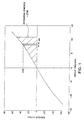
- Figure 1 shows an example of a torque-angle relationship for a rotational spring exhibiting such an elastic relationship. If the spring is not purely elastic, as is the case with all real springs, some amount of energy is lost as the spring rotates back through its displaced angle and only a portion of the stored energy is recoverable.
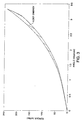
- Figures 2 and 3 show examples of torque-angle relationships for rotational springs exhibiting inelastic, "lossy" behaviour in which the amount of energy lost is represented by the area between the curves shown.
- a highly elastic spring is desirable, while in other applications a less elastic spring may be desirable.
- load capacity Another design criteria known as the load capacity, that is, the maximum torque that can be applied to the energy storage device without damaging it is also important.
- the volume required to house the energy storage device is also important.
- an energy storage device having a high load capacity and small package size would also be desirable.
- FR-A-2 465 920 discloses a rotational energy storage device that is substantially in accordance with the preamble of claim 1.
- a rotational energy storage device comprising a shaft, a ring rotatably disposed about said shaft, and at least one roller compressed between said shaft and said ring to form contact zones with each; a cam geometry means provided on a member that comprises said shaft, and/or said ring, and/or said at least one roller, wherein, upon relative rotation between said ring and said shaft, said at least one roller interferes with said ring and said shaft to convert and effect storage of mechanical energy created by the relative rotation of said ring and said shaft; characterised in that said cam geometry means comprises different profiles indexed to provide regions of low and high stiffness regions against each roller.
- a resonant oscillating mass-based torquing tool incorporating features of the device as just defined.
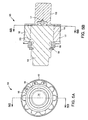
- Figures 4A, 4B, 5A, and 5B show a rotational energy storage device or spring which, according to a first embodiment, is a roller-cam assembly 10 comprising a shaft 14, a ring 12 rotatably disposed about the shaft, and at least one roller 16 disposed between the shaft 14 and ring 12.
- the at least one roller is positioned such that, upon rotating the ring relative to the shaft, the roller interferes with the ring and the shaft to convert and effect storage of mechanical energy created by the relative rotation of the ring and the shaft.
- a plurality of spaced rollers 16 are positioned as shown between the ring 12 and shaft 14.
- the shaft 14 is equipped with cam geometry means 20 which is either attached to or integral with the shaft.
- One end of shaft 14 acts as an input/output interface, as does a shaft member 13 which is attached to, and preferably integral with, the ring 12.
- the rollers 16 are disposed between and contact both the inner diameter of the ring 12 and cam geometry 20 of the shaft 14, creating two contact zones per roller.
- a light preload is typically utilised to hold the components in contact by designing the inner diameter of the ring 12 to interfere with the rollers, preferably, by press-or shrink-fitting the components of roller-cam assembly 10 together.
- roller-cam assembly 10 is typically completed by locating and holding an annular spacer 18 in place on shaft 14 using a retaining ring 19 as shown in Figures 5A and 5B.
- the shaft 14 and shaft member 13 are rotatably mounted with respect to each other and axially positioned by a thrust bearing 17 or other suitable means disposed therebetween as shown in Figure 5B.
- roller-cam assembly 10 Operation of the roller-cam assembly 10 will now be described with respect to the three roller-cam positions shown in Figures 6A-6C.
- a schematic planar view of a roller cam-assembly 10 is shown in these figures as having three rollers 16. Shown in Figure 6B is roller-cam assembly 10 in which the rollers 16 are at a zero-lift, minimum radial distance from the axis of shaft centre.
- the ring 12 In operation, upon applying a sufficient external torque to the ring 12 via the shaft member 13, the ring 12 rotates about the shaft 14. The rollers 16, in turn, are caused to roll on the cam geometry 20 of the shaft 14 and the ring 12 rolls on the rollers 16. If no cam geometry existed, the roller-cam assembly 10 would behave in a manner similar to that of a roller bearing. Because of the cam geometry, however, an angular deflection of the ring 12 relative to the shaft 14 from their positions in Fig. 6B results in a restoring torque which tends to drive the rollers back to their zero-lift positions.
- Fig. 6A Shown in Fig. 6A is the roller cam assembly upon counterclockwise rotation of the ring 12 from the zero-lift position of Fig. 6B while Figure 6C is the roller cam assembly upon clockwise rotation of the ring 12 from the zero-lift position of Fig. 6B.
- the position of the rollers 16 shown in Figures 6A and 6C are, respectively, upon the counterclockwise and clockwise rotation to cause an equal degree of radial interference between the rollers 16 and ring 12.
- the dotted outlines shown in Figs. 6A and 6C show the zero-lift position of the rollers 16 to illustrate their relative movement from their former positions shown in Fig. 6B.
- the roller-cam assembly 10 is ideally suited for providing a variety of torque-angle characteristics.
- a symmetrical torque-angular deflection characteristic such as that shown in Fig. 1 is desirable in which the magnitudes of the stiffness profile for the forward and reverse torsioning directions are the same.
- an asymmetrical torque-angular deflection characteristic is desirable in which the magnitudes of the stiffness profile differ in the forward and reverse torsioning directions.
- the cam geometry may be easily changed, devices having various torque-angle profiles may be designed and easily configured.
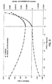
- the cam geometry means shown in Figures 6A-6C illustrate an example of one that provides the asymmetrical torque-angle behaviour shown in Figure 9.
- FIG. 9 At the origin of Fig. 9 is shown the torque and radial interference when the roller-cam assembly 10 is in the zero-lift roller-cam orientations shown in Figure 6B.
- Clockwise motion of the roller-cam assembly into the position shown in Fig. 6C corresponds to a positive angular direction from the origin shown in Figure 9.
- counterclockwise motion of the roller-cam assembly into the position shown in Fig. 6A corresponds to a negative angular direction from the origin in Figure 9.
- the roller-cam assembly acts as a potential energy storage device as follows.
- the rollers 16 orbit shaft 14.
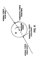
- the presence of the cam geometry 20 on shaft 14 forces rollers 16 to move radially outward creating a greater interference between rollers 16 and ring 12. Because of this interference, as shown in the free body diagrams of Fig. 8, after being deflected through some angle from the zero-lift position, a high normal force and a tangential frictional force are exerted on the roller 16 in each of the contact zones with the shaft 14 and ring 12.
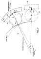
- Fig. 7 is a kinematic representation of the interference forces exerted on the ring 12 and shaft 14 caused by the roller 16 in driving the ring 12 counterclockwise from the neutral orientation of Fig. 6B (represented by dashed lines with relative positions of the roller 16 and ring 12 indicated with marker points P1 and P2, respectively) to the orientation of Fig. 6A (shown in solid lines with marker points P1 and P2, respectively, indicating subsequent relative positions of the roller 16 and ring 12).
- the greater interference caused by the roller 16 forces the ring 12 to expand as shown in Fig. 7 thereby storing potential energy. Additional storage of potential energy is caused by the compression of the rollers 16 and shaft 14 which also occurs.
- the roller-cam assembly 10 acts as a potential energy storage device in the following manner.
- the normal forces Nr and Ncs are equal in magnitude the direction of the normal force Ncs' acting on the cam geometry of the shaft 14 shifts so that it no longer passes through the centre of rotation of the shaft 14.
- a moment is exerted by this normal force Ncs' on the shaft 14 which combines with the moment caused by the tangential frictional force F1 to create a resultant torque on the shaft 14.
- a tangential frictional force F2 must exist between each roller 16 and the ring 12.
- asymmetrical cam geometry may be desirable to provide differing torque angle characteristics in each direction. If such an asymmetrical cam geometry such as that shown in Figs. 6A-6C is provided, if the ring 12 driven by the shaft 13 is rotated in the opposite rotational (i.e, clockwise) direction shown in Fig. 6C, the roller 16 is moved along a more rapidly rising cam geometry.
- a torque-angle characteristic may be produced that varies significantly depending on direction.
- This permits the storage or release of approximately equivalent amounts of potential energy with differing levels of restoring torque by tailoring the cam geometry as discussed above. It is important to note that the transition from counter-clockwise to clockwise rotation occurs smoothly without loss of contact between the components, and is therefore much quieter than other schemes that rely on breaking contact to change the torque-angle relationship.
- the cam geometry described above is designed so that the pressure angles developed between each roller 16 and the shaft 14 during relative rotation are small enough to prevent slipping.
- This design provides rolling action between the rollers 16 relative to the shaft 14.
- a cam geometry which permits slipping between the rollers 16 relative to shaft 14 may be employed to provide a torque-limiting feature or to otherwise create "lossy" behaviour described further in detail below.
- rollers and the shaft which also undergo deflection as the rollers rise radially, can be modified in applications where the ring 12 is constrained from flexing or cannot be made as flexible as the one considered in Figure 6. This may be accomplished, for example, by utilising a hollow shaft which flexes such as that shown in Figures 15A and 15B, which embodiment is described in greater detail below. Alternatively or additionally hollow rollers may be utilised for this purpose.
- roller-cam assembly 10 having cam geometry only disposed externally along shaft 14 in an axial direction
- alternative embodiments may be provided by equipping any of the three interacting components, i.e., shaft 13, rollers 16, ring 12, or combinations thereof with cam geometry which is symmetrical or asymmetrical.
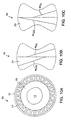
- FIG. 10A-D Shown in Figures 10A-D is an alternative embodiment in which the cam geometry is provided as a sprag geometry on the rollers.
- Shown in Figure 10B are sprags 21 having radii of curvature which are equal in the clockwise (Rcl) and counterclockwise (Rccl) directions.
- a roller cam assembly 25 may be provided which has a symmetrical torque-angle characteristic.
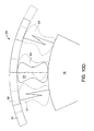
- Shown in Figure 10D is a portion of the roller cam assembly 25 depicted in Figure 10A upon a clockwise rotation of the ring 12.
- the dashed sprag bodies are provided to represent the position of the sprags 21 after the ring 12 has been rotated through a small clockwise angle, as shown by the dashed extension of the ring. Interference can be detected between each sprag body and the ring. These interferences cause high normal forces resulting in tangential frictional forces which maintain equilibrium. These tangential frictional forces, acting at a distance from the centre of rotation, provide restoring torques as discussed in detail above.
- Shown in Figure 10C is an alternative sprag 23 configuration in which the radii of curvature are not equal in the clockwise (Rcl') and counterclockwise (Rccl') directions.
- a roller-cam assembly 25 having an asymmetrical behaviour may also be provided by replacing the sprags 21 with sprags 23 thereby providing different radii which are active in each of the clockwise and counterclockwise directions (shown as Rcl and Rccl, respectively) depending on which direction the ring 12 is rotated from the zero lift position.
- Rcl and Rccl respectively
- the sprags useful in the present construction are similar to those used in overrunning clutches as is known in the art. Examples of such sprags are those manufactured by the Formsprag Company, Warren, Michigan, U.S.A. Although such sprags operate in overrunning clutches to permit rotating members to run freely relative to one another by slipping in one rotational direction while locking the members together in the other rotational direction they differ in their operation in the present roller cam by transmitting torque in both rotational directions and allowing no free running.
- FIG. 11A and 11B Shown in Figures 11A and 11B is another embodiment of a roller-cam assembly 40 in which cam geometry means is provided as a cam geometry 43 on the interior surface of a ring 42.
- the cam geometry 43 may be used as the sole cam geometry means or in combination with other cam geometries.
- torque-angle relationship may be controlled to realize a beneficial result; the "net pressure angle" can be kept very close to zero across the range of motion of the roller. While the pressure angle between the roller and the cam on the shaft remains, a new pressure angle is introduced at the ring/roller interface which can be designed such that the normal forces acting on the roller are effectively directly opposed. As a result the dislodging effect on the rollers is greatly reduced thereby providing a robust design under varying lubricating conditions. In this manner the range of materials which may be employed to construct roller-cam assembly 40 is increased thereby providing greater design flexibility.
- the mechanism torque-angle behaviour can be modified by use of a back-up ring 52 which is concentrically located about and contacts ring 12 of a roller-cam assembly 50, and can be rotated relative to it.
- the back-up ring 52 includes pockets 53 which are oriented relative to cam geometry 51 to vary the deformation of the ring 12 as described below.
- Shown in Fig. 12 is such a configuration having a roller-cam assembly 50 which is similar to the roller cam assembly 10 described above except that the shaft 14 incorporates a symmetrical cam geometry 51 on both sides of each of a plurality of equally spaced zero lift positions.
- a concentric back-up ring 52 which is in light radial contact with the ring 12.
- the concentric back-up ring 52 is provided with a plurality of pockets or reliefs 53 on the inner diameter to provide thick and thin wall thicknesses which are indexed to define alternating high stiffness regions and low stiffness regions which, in turn, provide greater tightening torque than loosening torque, respectively.
- the ability to rotate the pocketed back-up ring 53 relative to the ring 12 allows the torque-angle relation to be modified and reversed.
- the roller-cam device may be incorporated into a resonant reactionless torquing tool.
- the flexibility of design with regard to the torque-angle relationship provided by the roller-cam assembly including its ability to provide much greater torsional stiffness in one direction than the other, makes it an ideal mechanism for such a tool.
- the roller-cam assembly When excited to resonance, the roller-cam assembly would convert kinetic energy to potential energy in a much smaller angle in one direction than the other, thus developing much higher torque in that direction.
- a fastener to be tightened is rotated in the high-torque direction, but does not back up under the lower torque developed in the opposite direction.
- the resonant system requires low loss in order to achieve high gain-the rolling (as opposed to sliding) elements of the roller-cam assembly of the present construction may be used to provide this; thus a relatively small motor can be used to develop high torque.
- the smooth rolling transition between soft and stiff behaviour of the roller-cam assembly would also provide a tool which is more quiet in operation, a trait which is especially desirable for tools which are to be used for extended periods of time.
- roller-cam assembly may be adapted to couple the shaft member 13 directly to a rotor of a DC motor such as the flywheel rotor 4 shown in Fig. 1 in U./S. Patent Application No. 08/865,043.
- Shown in Figure 13 is a schematic representation of an example of an oscillating mass-based tool which incorporates one embodiment of the present roller-cam assembly.
- the roller-cam assembly 10 would replace the dual-stiffness spring of the rotating spring-mass oscillator of the patent application just mentioned, with the roller-cam ring 12 and the rotor 34 acting as the oscillating mass.
- the shaft member 13 is rigidly engaged for rotation with a spindle 33 driven by a rotor 34.
- the shaft 14 of the roller cam assembly 10 would be configured to interface with a socket 35 for tightening threaded fasteners which as shown in Fig. 1 of the patent application just mentioned may be a collet type socket or other clamping means.
- the rotor By supplying energy from the motor in phase with the rotor's velocity, the rotor is oscillated in a resonant or near-resonant mode.
- the rotor reaches peak velocity at the zero lift position of the roller cam, as shown in Figure 6B.
- the rotor and the ring 12, which is directly coupled to it are rotating rapidly about the shaft 14.
- a great amount of kinetic energy is stored in them by virtue of their rotational mass moment of inertia and their angular velocity.
- the roller cam As the roller cam is deflected from the zero lift position, the restoring torque which is a function of cam geometry and forces due to interference, begin to rise.
- This torque acts to negatively accelerate the rotor/ring inertia; the rotor/ring inertia performs work on the roller cam spring, and the kinetic energy from the inertia is converted to potential energy in the roller cam.
- the restoring torque continues to negatively accelerate the rotor/ring inertia until it brings this inertia to a stop, and a great amount of potential energy is stored in the roller cam.
- the restoring torque which has stopped the motion of the rotor/ring inertia now begins to accelerate them in the opposite direction, and the potential energy in the roller cam is returned to kinetic energy in the rotor/ring inertia.
- the roller cam is able to stop the rotor/ring inertia in a shorter rotation angle and a shorter time such that a higher restoring torque is developed.
- the potential energy remaining in the roller cam will be returned to the rotor/ring, accelerating them in the counterclockwise direction.
- the motor continues to drive the rotor/ring in phase with their angular velocity, and energy continues to be delivered to the oscillator.
- the torque developed in the shaft 14 during a counterclockwise rotation from the zero lift position is not great enough to rotate the fastener counterclockwise, and it will be rotated forward again when high torque is encountered on a relative clockwise rotation of the ring.
- the roller-cam assembly may be used as a rotational spring-inertia oscillator having a torque angle characteristic that varies depending on direction of rotation such that a higher torque is provided in one rotational direction than the other (i.e., by incorporating an asymmetrical cam geometry such as that provided in Figure 6).
- the higher torque direction can be use to tighten a threaded fastener.
- the roller-cam assembly 10 may be used as a rotational spring-inertia oscillator which is "DC biased" (i.e., by incorporating a symmetrical cam geometry to provide a non-zero mean torque using a D.C. pulse motor as described in U.S. patent application No. 08/865,037).
- the roller-cam assembly could use a motor with a lower torque output than that required to tighten the threaded fastener. This is accomplished by using the motor to drive the rotational spring-inertia oscillator in phase with rotor velocity such that the power input to the system is always positive. The resulting angular deflections of the system and the angular velocity of the rotor would continue to grow until the torque developed in the output shaft is sufficient to overcome the fastener torque, at which time the fastener is rotated forward through some angle. Energy is built up again in the oscillator until the new level of torque in the fastener is overcome, at which point the fastener is tightened further.
- a portable tool which is both lightweight and has a relatively small package size may be achieved by using a smaller output torque motor while still providing a tool having a high output and high torque capacity.
- operating components such as a front support bearing 28, a rear support bearing 26, a motor stator 32, a trigger switch 30, and a power control cable 36, these components are provided to show a preferred mode of incorporating the roller cam assembly into an oscillating mass-based torquing tool.
- Other components of construction generally understood with respect to the basic operation of such a tool will be readily recognized and are therefore not shown for reasons of clarity.
- FIG. 14A and 14B Shown in Figures 14A and 14B, is a cam geometry on shaft 14 which may be used to reverse the torque-angle relationship of roller-cam assembly 10. As shown in Figures 14A and 14B, the cam geometry is mirrored across the high point of the cam rise.
- the roller-cam assembly 10 When incorporated into a tool such as that shown and described above with respect to Figure 13, the roller-cam assembly 10 may be reversed by exciting the oscillating mass (i.e., rotor 34) sufficiently by an oscillating torque from the DC motor to roll the rollers 16 over the top of the cam rise and into the stable operating regime on the opposite side (i.e., the reverse position) as shown in Figure 14B.
- This reversal may also be accomplished manually by rotating the ring 12 to move the rollers 16 over the top of the cam rise.
- the excitation is bounded such that the roller excursion does not result in reversal of the torque-angle relationship.
- FIG. 12 having a back-up ring 52 may be reversed by rotating the back-up ring independently of and about the ring 12 so that the orientation of the pockets 53 is reversed (i.e., mirror-imaged about the zero-lift position of the cam geometry 51).
- the regions of alternating high and low stiffness are reversed so that the roller-cam assembly 50 will develop a higher torque when the ring 12 and back-up ring 52 are rotated together in a clockwise direction from the zero-lift position than when they are rotated in a clockwise direction.
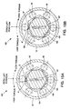
- Shown in Figures 15A and 15B is another embodiment of a roller-cam assembly 60 which is reversible.
- the roller-cam assembly 60 is similar to the roller-cam assembly 10 shown in Figs. 4A and 4B except that the solid, shaft 14 is replaced with a hollow shaft 64 having an internal bore 65 and a reversing mechanism 66 located and rotatable in the bore 65.
- the rotation of the reversing mechanism 66 in the bore 65 is limited by an index key 67 which fits in a slot located within the reversing mechanism 66 and extends axially therefrom for rotation between the positions shown in Figures 15A and 15B.
- Reversal of the roller-cam 60 is accomplished by rotating the reversing mechanism 66 in bore 65. In the position shown in Fig.
- the reversing mechanism 66 provides rigid support to the hollow shaft 64 at the interface of the bore 65 along the arc designated by the points "A-B.”
- the rigid support zone provided by the reversing mechanism 66 develops a higher torque when the ring 12 is rotated in the counter-clockwise direction from the zero-lift position than when the ring 12 is rotated in the clockwise direction.
- the rigid support zone provided to the hollow shaft 64 is moved along the arc of the bore 65 designated by the points "A'-B' ". In this position the roller-cam assembly 60 is reversed such that a higher torque is now developed when the ring 12 is rotated in the clockwise direction from the zero lift position than when the ring 12 is rotated in the counter-clockwise direction.
- roller-cam assemblies having definite numbers of rollers
- any number of rollers may be employed depending upon the rolling characteristics desired. All that is required is that at least one of the rollers employed in the roller-cam assembly provide interference between the ring and shaft such that energy is stored as described above. Additional rollers may be provided to provide additional interference or which do not interfere but merely provide rolling support between the ring and shaft.
Landscapes
- Engineering & Computer Science (AREA)
- General Engineering & Computer Science (AREA)
- Mechanical Engineering (AREA)
- Physics & Mathematics (AREA)
- Acoustics & Sound (AREA)
- Aviation & Aerospace Engineering (AREA)
- Transmission Devices (AREA)
- Friction Gearing (AREA)
- Press Drives And Press Lines (AREA)
- Folding Of Thin Sheet-Like Materials, Special Discharging Devices, And Others (AREA)
- Connection Of Motors, Electrical Generators, Mechanical Devices, And The Like (AREA)
Abstract
Description
- The invention relates generally to rotational energy storage devices including springs and more particularly to rotational energy storage devices that may be used in inertia based torquing tools.
- Springs are components or devices that, with high efficiency, store energy as they deflect under an applied force, e.g., torque, force, bending moment, or any combination thereof, and release the stored energy as they return to their original position when the applied force is removed. Their primary characteristic is that they deflect either linearly or non-linearly in proportion to the amplitude and direction of the applied force. Various types of springs are used in machines and tools to store energy as they deflect and react applied forces. Some examples of real springs include helical-wound torsion springs, helical-wound compression springs, torsion bars, multiple-leaf springs, and gas-filled bladders.
- Springs are used in various applications, e.g., in low reaction tools for tightening threaded fasteners. These tools are typically devices that accelerate a rotary inertia mass through a relatively large travel angle. This acceleration is developed using a motor with a torque output that is relatively low compared to the output torque capability of the tool. As the inertia mass accelerates, it develops kinetic energy. After the inertia mass has travelled through a significant angle (for example, 180 degrees or more), a clutching means engages the rotary inertia mass to a workpiece, via some type of torsion spring. The subsequent negative acceleration of the inertia mass results in a torque output that is relatively high compared to that supplied by the accelerating motor. This high torque output is not reacted on the user, as the reaction is provided by the torque associated with the negative acceleration of the flywheel or inertia mass.
- In order to tighten a threaded fastener, one must rotate a bolt via applying a torque to clamp a joint. All bolts have some lead or helix angle that permits the clockwise rotation, for right-hand fasteners, to translate a nut or member to cause tension in the bolt. This angle makes the bolt more difficult to turn (i.e., higher torque) when clamping a joint versus the reverse direction, which is loosening a joint. When considering a low reaction tool with an oscillatory drive system, having an energy storage device which applies an equal forward and reverse torque to the fastener will cause the joint to loosen for the reason discussed above.
- In U.S. Patent Application No. 08/865,037 titled "Resonant Oscillating Mass-Based Torquing Tool", a resonant torquing tool is disclosed which overcomes this obstacle by applying a bias torque on the drive motor so that the developed tightening torque is greater that the loosening torque. This bias torque, however, creates a bias torque on the tool housing which must be reacted by the operator. For low torque range tools, where the bias torque would be small, this may be appropriate.
- In U.S. Patent Application No. 08/865,043 titled "Oscillating Mass-Based Tool With Dual Stiffness Spring," a resonant torquing tool is disclosed which uses a dual stiffness spring. As taught therein, the dual stiffness spring has a greater resistance to torsion (i.e., greater stiffness) in the tightening direction and a smaller resistance to torsion (i.e., softer stiffness) in the loosening direction. The energy used for torquing a workpiece is developed by oscillating a mass spring system at or near its resonant frequency, with the means for biasing the output torque being provided by the dual stiffness spring. This system provides for a reactionless tightening system by significantly reducing or eliminating the resultant net torque on the tool housing. As a result, this system is particularly well suited for higher torque range tools.
- In designing springs for these low reaction torquing tools, as well as for a variety of other applications, one important characteristic is how the torque applied varies with the angular displacement of the spring. Dual stiffness springs such as those described in U.S. Patent Application No. 08/865,043 provide for torque-angle relationships (i.e., spring stiffnesses) that differ depending on the direction of applied torque. While these stiffnesses differ in the forward and reverse torsioning directions, they are only slightly non-linear in each direction, and, while not impossible, it is not easy to tailor the torque-angle relationship of these springs to provide various linear or non-linear stiffness profiles in either or both directions. It would be desirable to provide a spring in which the torque-angle relationship could be easily tailored to provide a substantially different linear or non-linear spring stiffness when being deflected in either or both directions. This would provide designers and engineers greater flexibility than that provided by typical torsion springs and bars.
- When torque is applied to a rotational spring such that it displaces angularly, work is done on the spring and the spring stores energy. If the spring is purely elastic, all the energy stored is recoverable by allowing the spring to rotate back through its displaced angle, and the spring is said to be 100% efficient. Figure 1 shows an example of a torque-angle relationship for a rotational spring exhibiting such an elastic relationship. If the spring is not purely elastic, as is the case with all real springs, some amount of energy is lost as the spring rotates back through its displaced angle and only a portion of the stored energy is recoverable. Figures 2 and 3 show examples of torque-angle relationships for rotational springs exhibiting inelastic, "lossy" behaviour in which the amount of energy lost is represented by the area between the curves shown. In many applications a highly elastic spring is desirable, while in other applications a less elastic spring may be desirable. Thus, it would be desirable to provide a spring design in which the degree of elasticity can easily be varied, from almost 100% efficiency to some desired lower efficiency.
- Another design criteria known as the load capacity, that is, the maximum torque that can be applied to the energy storage device without damaging it is also important. In many applications, the volume required to house the energy storage device is also important. Thus, an energy storage device having a high load capacity and small package size would also be desirable.
- FR-A-2 465 920 discloses a rotational energy storage device that is substantially in accordance with the preamble of claim 1.
- According to the present invention, there is provided a rotational energy storage device comprising a shaft, a ring rotatably disposed about said shaft, and at least one roller compressed between said shaft and said ring to form contact zones with each; a cam geometry means provided on a member that comprises said shaft, and/or said ring, and/or said at least one roller, wherein, upon relative rotation between said ring and said shaft, said at least one roller interferes with said ring and said shaft to convert and effect storage of mechanical energy created by the relative rotation of said ring and said shaft; characterised in that said cam geometry means comprises different profiles indexed to provide regions of low and high stiffness regions against each roller.
- Also provided is a resonant oscillating mass-based torquing tool incorporating features of the device as just defined.
- For a better understanding of the invention and to show how the same may be carried into effect, reference will now be made, by way of example, to the accompanying drawings, in which:-
- Figure 1 is a graph showing a torque angle relation for a rotational energy storage device having an elastic behaviour;
- Figure 2 is a graph showing the torque angle relation for a rotational energy storage device having a "lossy" behaviour;
- Figure 3 is a graph showing the torque angle relation for a rotational energy storage device similar to that in Figure 2 but having lower "lossy" behaviour;
- Figure 4A is an isometric view of a partially assembled rotational energy storage device;
- Figure 4B is a front view of the partially assembled rotational energy storage device shown in Figure 4A;
- Figure 5A is a front view of the rotational energy storage device shown in Figures 4A and 4B with an annular spacer and retaining ring to maintain assembly of the component parts;
- Figure 5B is an axial sectional view of the rotational energy storage device shown in Figure 5A taken along the sectional line "5B-5B";
- Figure 6A is a schematic transverse sectional view of the rotational energy storage device shown in Figure 6B upon counterclockwise rotation from the zero-lift position; Figure 6B is a schematic transverse sectional view corresponding to the rotational energy storage device shown in Figure 4A taken along the line "6B-6B" with three representative rollers at the zero-lift position;
- Figure 6C is a schematic transverse sectional view of the rotational energy storage device shown in Figure 6B upon clockwise rotation from the zero-lift position;
- Figure 7 is a kinematic representation of the interference forces caused in the rotational energy storage device in driving ring counterclockwise from the neutral orientation of Figure 6B to the position shown in Figure 6A;
- Figure 8 is a free body diagram illustrating the normal and tangential frictional forces in each of the contact zones exerted on a roller by the shaft and ring of the rotational energy storage device shown in Figures 4-5;
- Figure 9 is a graph showing the torque-angle relationship and radial displacement for the rotational energy storage device shown in Figure 6B as it is rotated from the zero-lift position to the counter-clockwise and clockwise positions shown in Figures 6A and 6C, respectively;
- Figures 10A is an end view of an alternative embodiment of a rotational energy storage device having rollers with sprag geometries;
- Figure 10B is an enlarged view of the sprag geometry shown in Fig. 10A which provides a symmetrical torque-angle characteristic;
- Figure 10C is an enlarged view of an alternative sprag geometry which may be incorporated into the rotational energy storage device shown in Fig. 10A to provide an asymmetrical torque-angle characteristic;
- Figure 10D is a partial view of the rotational energy storage device in Figure 10A rotated in a clockwise direction;
- Figure 11A is an isometric view of a partially assembled rotational energy storage device according to another embodiment;
- Figure 11B is a front view of the partially assembled rotational energy storage device shown in Figure 11A with a roller removed to show a cam geometry on an interior ring surface;
- Figure 12 is an end view of an alternative embodiment of a rotational energy storage device having a pocketed back-up ring;
- Figure 13 is a cross-sectional view oscillating mass-based tool which incorporates a roller-cam assembly;
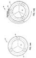
- Figures 14A and 14B are schematic end views illustrating a cam geometry for reversing the torque-angle relationship of a rotational energy storage device; and
- Figures 15A and 15B are transverse sectional views of an embodiment of a rotational energy storage device which is reversible.
-
- In the accompanying drawings, like reference numbers refer to like parts. Various dimensions of the parts shown are not to scale and have been enlarged for clarity.
- Figures 4A, 4B, 5A, and 5B show a rotational energy storage device or spring which, according to a first embodiment, is a roller-
cam assembly 10 comprising ashaft 14, aring 12 rotatably disposed about the shaft, and at least oneroller 16 disposed between theshaft 14 andring 12. The at least one roller is positioned such that, upon rotating the ring relative to the shaft, the roller interferes with the ring and the shaft to convert and effect storage of mechanical energy created by the relative rotation of the ring and the shaft. Preferably a plurality of spacedrollers 16 are positioned as shown between thering 12 andshaft 14. - As can be seen by the partial construction in Figures 4A and 4B, the
shaft 14 is equipped with cam geometry means 20 which is either attached to or integral with the shaft. One end ofshaft 14 acts as an input/output interface, as does ashaft member 13 which is attached to, and preferably integral with, thering 12. Therollers 16 are disposed between and contact both the inner diameter of thering 12 andcam geometry 20 of theshaft 14, creating two contact zones per roller. A light preload is typically utilised to hold the components in contact by designing the inner diameter of thering 12 to interfere with the rollers, preferably, by press-or shrink-fitting the components of roller-cam assembly 10 together. Construction of the roller-cam assembly 10 is typically completed by locating and holding anannular spacer 18 in place onshaft 14 using a retainingring 19 as shown in Figures 5A and 5B. Theshaft 14 andshaft member 13 are rotatably mounted with respect to each other and axially positioned by athrust bearing 17 or other suitable means disposed therebetween as shown in Figure 5B. - Operation of the roller-
cam assembly 10 will now be described with respect to the three roller-cam positions shown in Figures 6A-6C. To simplify the explanation of the operation of the roller-cam device, a schematic planar view of a roller cam-assembly 10 is shown in these figures as having threerollers 16. Shown in Figure 6B is roller-cam assembly 10 in which therollers 16 are at a zero-lift, minimum radial distance from the axis of shaft centre. - In operation, upon applying a sufficient external torque to the
ring 12 via theshaft member 13, thering 12 rotates about theshaft 14. Therollers 16, in turn, are caused to roll on thecam geometry 20 of theshaft 14 and thering 12 rolls on therollers 16. If no cam geometry existed, the roller-cam assembly 10 would behave in a manner similar to that of a roller bearing. Because of the cam geometry, however, an angular deflection of thering 12 relative to theshaft 14 from their positions in Fig. 6B results in a restoring torque which tends to drive the rollers back to their zero-lift positions. - Shown in Fig. 6A is the roller cam assembly upon counterclockwise rotation of the
ring 12 from the zero-lift position of Fig. 6B while Figure 6C is the roller cam assembly upon clockwise rotation of thering 12 from the zero-lift position of Fig. 6B. The position of therollers 16 shown in Figures 6A and 6C are, respectively, upon the counterclockwise and clockwise rotation to cause an equal degree of radial interference between therollers 16 andring 12. The dotted outlines shown in Figs. 6A and 6C show the zero-lift position of therollers 16 to illustrate their relative movement from their former positions shown in Fig. 6B. - The roller-
cam assembly 10 is ideally suited for providing a variety of torque-angle characteristics. In some applications, a symmetrical torque-angular deflection characteristic such as that shown in Fig. 1 is desirable in which the magnitudes of the stiffness profile for the forward and reverse torsioning directions are the same. In other applications, an asymmetrical torque-angular deflection characteristic is desirable in which the magnitudes of the stiffness profile differ in the forward and reverse torsioning directions. Moreover, because the cam geometry may be easily changed, devices having various torque-angle profiles may be designed and easily configured. The cam geometry means shown in Figures 6A-6C illustrate an example of one that provides the asymmetrical torque-angle behaviour shown in Figure 9. - At the origin of Fig. 9 is shown the torque and radial interference when the roller-
cam assembly 10 is in the zero-lift roller-cam orientations shown in Figure 6B. Clockwise motion of the roller-cam assembly into the position shown in Fig. 6C corresponds to a positive angular direction from the origin shown in Figure 9. Conversely, counterclockwise motion of the roller-cam assembly into the position shown in Fig. 6A corresponds to a negative angular direction from the origin in Figure 9. Upon inspection of Figure 9, it can be seen that a given positive angular deflection results in a much greater torque magnitude than does an equal but opposite negative angular deflection. - Although not intending to be bound to or otherwise limited by any theory, by this construction, the roller-cam assembly acts as a potential energy storage device as follows. As the
ring 12 driven by theshaft 13 rotates as shown in Fig. 6A, therollers 16orbit shaft 14. The presence of thecam geometry 20 onshaft 14forces rollers 16 to move radially outward creating a greater interference betweenrollers 16 andring 12. Because of this interference, as shown in the free body diagrams of Fig. 8, after being deflected through some angle from the zero-lift position, a high normal force and a tangential frictional force are exerted on theroller 16 in each of the contact zones with theshaft 14 andring 12.
The normal forces created by the interference of the ring and by the cam geometry which are exerted on the rollers, cause equal and opposite forces Nr and Ncs to be exerted on thering 12 andshaft 14, respectively. Shown in Fig. 7 is a kinematic representation of the interference forces exerted on thering 12 andshaft 14 caused by theroller 16 in driving thering 12 counterclockwise from the neutral orientation of Fig. 6B (represented by dashed lines with relative positions of theroller 16 andring 12 indicated with marker points P1 and P2, respectively) to the orientation of Fig. 6A (shown in solid lines with marker points P1 and P2, respectively, indicating subsequent relative positions of theroller 16 and ring 12). In moving to the orientation shown in Fig. 6A, the greater interference caused by theroller 16 forces thering 12 to expand as shown in Fig. 7 thereby storing potential energy. Additional storage of potential energy is caused by the compression of therollers 16 andshaft 14 which also occurs. - Thus, applying a torque to the
shaft 13 results in an angular deflection of the ring about theshaft 14. At each angularly deflected position, a restoring torque exists. As illustrated in Figure 1, the integral of the torque applied through the angle of rotation about theshaft 14 is equal to the work done on the roller cam spring in deforming it. Energy, defined as the capacity to do work, resides in the spring, and may be released by reducing the torque applied to the shaft. As the torque applied is reduced, the roller cam tends to return to its zero-lift position, and the energy stored in the spring is released as the roller cam performs work on theshaft 13. - In greater detail, although not intending to be bound to or otherwise limited by any theory, the roller-
cam assembly 10 acts as a potential energy storage device in the following manner. As shown in Figure 7, as the roller moves up the cam away from the zero-lift position, although the normal forces Nr and Ncs are equal in magnitude the direction of the normal force Ncs' acting on the cam geometry of theshaft 14 shifts so that it no longer passes through the centre of rotation of theshaft 14. As a result, a moment is exerted by this normal force Ncs' on theshaft 14 which combines with the moment caused by the tangential frictional force F1 to create a resultant torque on theshaft 14. In order to maintain equilibrium of the roller, a tangential frictional force F2 must exist between eachroller 16 and thering 12. The sum of all of these tangential frictional forces F2 acting at each of the roller/ring interfaces at a moment arm equal to the radial distance from the centre of shaft rotation Cr, result in a restoring torque on thering 12. Thus, the torque exerted on thering 12 at any deflected position depends on the normal and tangential forces with the normal force depending mainly on the radial interference between the roller and the ring caused by the cam geometry. - Moreover, although it is envisaged that the storage of potential energy discussed above may be accomplished by providing cam geometry that is symmetrical with respect to the zero-lift position, for various applications such as those discussed in detail below an asymmetrical cam geometry may be desirable to provide differing torque angle characteristics in each direction. If such an asymmetrical cam geometry such as that shown in Figs. 6A-6C is provided, if the
ring 12 driven by theshaft 13 is rotated in the opposite rotational (i.e, clockwise) direction shown in Fig. 6C, theroller 16 is moved along a more rapidly rising cam geometry. In Figure 6C, a significantly smaller angle has been required to obtain the same radial interference as that obtained in Figure 6A and the pressure angle (i.e., the angle between a normal to the contact point between the roller and the shaft and a radial line extending from the centre of rotation, Cr, to the centre of the roller) is greater. Although the equal radial interferences in each direction results in equal normal forces being exerted in the contact zones with the roller, the greater pressure angle of the cam geometry in the clockwise direction requires higher tangential frictional forces to maintain equilibrium of the roller. As a result, these higher tangential frictional forces acting at each roller/ring interface result in a higher restoring torque when moving thering 12 from the zero-lift position in the clockwise direction than in the counterclockwise direction. - Hence by providing a cam geometry which is asymmetrical about the zero-lift position, that is, one in which the cam rise and rate of rise differ depending on rotation direction, a torque-angle characteristic may be produced that varies significantly depending on direction. This, in turn, permits the storage or release of approximately equivalent amounts of potential energy with differing levels of restoring torque by tailoring the cam geometry as discussed above. It is important to note that the transition from counter-clockwise to clockwise rotation occurs smoothly without loss of contact between the components, and is therefore much quieter than other schemes that rely on breaking contact to change the torque-angle relationship.
- Preferably, to prevent loss of energy in the system, the cam geometry described above is designed so that the pressure angles developed between each
roller 16 and theshaft 14 during relative rotation are small enough to prevent slipping. This design provides rolling action between therollers 16 relative to theshaft 14. Alternatively, a cam geometry which permits slipping between therollers 16 relative toshaft 14 may be employed to provide a torque-limiting feature or to otherwise create "lossy" behaviour described further in detail below. - While the embodiment incorporating the principles discussed above has great utility, variations that provide the ability to tailor the design torque-angle characteristics for various applications may also be incorporated. For instance, the rollers and the shaft, which also undergo deflection as the rollers rise radially, can be modified in applications where the
ring 12 is constrained from flexing or cannot be made as flexible as the one considered in Figure 6. This may be accomplished, for example, by utilising a hollow shaft which flexes such as that shown in Figures 15A and 15B, which embodiment is described in greater detail below. Alternatively or additionally hollow rollers may be utilised for this purpose. - Moreover, although shown and described above with respect to a roller-
cam assembly 10 having cam geometry only disposed externally alongshaft 14 in an axial direction, it will be readily recognized that alternative embodiments may be provided by equipping any of the three interacting components, i.e.,shaft 13,rollers 16,ring 12, or combinations thereof with cam geometry which is symmetrical or asymmetrical. - Shown in Figures 10A-D is an alternative embodiment in which the cam geometry is provided as a sprag geometry on the rollers. Shown in Figure 10B are
sprags 21 having radii of curvature which are equal in the clockwise (Rcl) and counterclockwise (Rccl) directions. By mating thesprags 21 between thering 12 which acts as an outer race and a circularinner race 22 mounted on theshaft 14 as shown in Figure 10A, aroller cam assembly 25 may be provided which has a symmetrical torque-angle characteristic. - Shown in Figure 10D is a portion of the
roller cam assembly 25 depicted in Figure 10A upon a clockwise rotation of thering 12. The dashed sprag bodies are provided to represent the position of thesprags 21 after thering 12 has been rotated through a small clockwise angle, as shown by the dashed extension of the ring. Interference can be detected between each sprag body and the ring. These interferences cause high normal forces resulting in tangential frictional forces which maintain equilibrium. These tangential frictional forces, acting at a distance from the centre of rotation, provide restoring torques as discussed in detail above. Shown in Figure 10C is analternative sprag 23 configuration in which the radii of curvature are not equal in the clockwise (Rcl') and counterclockwise (Rccl') directions. A roller-cam assembly 25 having an asymmetrical behaviour may also be provided by replacing thesprags 21 withsprags 23 thereby providing different radii which are active in each of the clockwise and counterclockwise directions (shown as Rcl and Rccl, respectively) depending on which direction thering 12 is rotated from the zero lift position. Thus the operation of the sprag-basedroller cam assembly 25 is similar in nature to the behaviour discussed in relation to the roller-cam assembly 10 shown in Figure 6 and described in detail above. - The sprags useful in the present construction are similar to those used in overrunning clutches as is known in the art. Examples of such sprags are those manufactured by the Formsprag Company, Warren, Michigan, U.S.A. Although such sprags operate in overrunning clutches to permit rotating members to run freely relative to one another by slipping in one rotational direction while locking the members together in the other rotational direction they differ in their operation in the present roller cam by transmitting torque in both rotational directions and allowing no free running.
- Shown in Figures 11A and 11B is another embodiment of a roller-
cam assembly 40 in which cam geometry means is provided as acam geometry 43 on the interior surface of aring 42. Thecam geometry 43 may be used as the sole cam geometry means or in combination with other cam geometries. For example, by providing both thecam geometry 43 on thering 42 andcam geometry 20 on theshaft 14, as shown, torque-angle relationship may be controlled to realize a beneficial result; the "net pressure angle" can be kept very close to zero across the range of motion of the roller. While the pressure angle between the roller and the cam on the shaft remains, a new pressure angle is introduced at the ring/roller interface which can be designed such that the normal forces acting on the roller are effectively directly opposed. As a result the dislodging effect on the rollers is greatly reduced thereby providing a robust design under varying lubricating conditions. In this manner the range of materials which may be employed to construct roller-cam assembly 40 is increased thereby providing greater design flexibility. - In yet another embodiment, the mechanism torque-angle behaviour can be modified by use of a back-up
ring 52 which is concentrically located about and contacts ring 12 of a roller-cam assembly 50, and can be rotated relative to it. The back-upring 52 includespockets 53 which are oriented relative tocam geometry 51 to vary the deformation of thering 12 as described below. Shown in Fig. 12 is such a configuration having a roller-cam assembly 50 which is similar to theroller cam assembly 10 described above except that theshaft 14 incorporates asymmetrical cam geometry 51 on both sides of each of a plurality of equally spaced zero lift positions. Also provided around thering 12 is a concentric back-upring 52 which is in light radial contact with thering 12. The concentric back-upring 52 is provided with a plurality of pockets orreliefs 53 on the inner diameter to provide thick and thin wall thicknesses which are indexed to define alternating high stiffness regions and low stiffness regions which, in turn, provide greater tightening torque than loosening torque, respectively. As discussed in greater detail below, the ability to rotate the pocketed back-upring 53 relative to thering 12 allows the torque-angle relation to be modified and reversed. - It will be appreciated that similar behaviour can be achieved by other means which provide high and low stiffness regions, for example by providing a pocketed internal shaft as shown in Figs. 15A and 15B or by providing pockets in the main internal shaft that can be basically empty or full of supporting material to provide the high stiffness and low stiffness behaviour discussed above.
- It will be further appreciated that there are various applications where the present roller cam device is particularly useful. For example, the roller-cam device may be incorporated into a resonant reactionless torquing tool. The flexibility of design with regard to the torque-angle relationship provided by the roller-cam assembly, including its ability to provide much greater torsional stiffness in one direction than the other, makes it an ideal mechanism for such a tool. When excited to resonance, the roller-cam assembly would convert kinetic energy to potential energy in a much smaller angle in one direction than the other, thus developing much higher torque in that direction. As a result, a fastener to be tightened is rotated in the high-torque direction, but does not back up under the lower torque developed in the opposite direction. The resonant system requires low loss in order to achieve high gain-the rolling (as opposed to sliding) elements of the roller-cam assembly of the present construction may be used to provide this; thus a relatively small motor can be used to develop high torque. The smooth rolling transition between soft and stiff behaviour of the roller-cam assembly would also provide a tool which is more quiet in operation, a trait which is especially desirable for tools which are to be used for extended periods of time.
- It is envisaged that the roller-cam assembly may be adapted to couple the
shaft member 13 directly to a rotor of a DC motor such as theflywheel rotor 4 shown in Fig. 1 in U./S. Patent Application No. 08/865,043. - Shown in Figure 13 is a schematic representation of an example of an oscillating mass-based tool which incorporates one embodiment of the present roller-cam assembly. In such a configuration, the roller-
cam assembly 10 would replace the dual-stiffness spring of the rotating spring-mass oscillator of the patent application just mentioned, with the roller-cam ring 12 and therotor 34 acting as the oscillating mass. As shown in Fig. 13, theshaft member 13 is rigidly engaged for rotation with aspindle 33 driven by arotor 34. Theshaft 14 of theroller cam assembly 10 would be configured to interface with asocket 35 for tightening threaded fasteners which as shown in Fig. 1 of the patent application just mentioned may be a collet type socket or other clamping means. - By supplying energy from the motor in phase with the rotor's velocity, the rotor is oscillated in a resonant or near-resonant mode. The rotor reaches peak velocity at the zero lift position of the roller cam, as shown in Figure 6B. At this point, the rotor and the
ring 12, which is directly coupled to it, are rotating rapidly about theshaft 14. A great amount of kinetic energy is stored in them by virtue of their rotational mass moment of inertia and their angular velocity. As the roller cam is deflected from the zero lift position, the restoring torque which is a function of cam geometry and forces due to interference, begin to rise. This torque acts to negatively accelerate the rotor/ring inertia; the rotor/ring inertia performs work on the roller cam spring, and the kinetic energy from the inertia is converted to potential energy in the roller cam. As the roller cam continues to rotate, the restoring torque continues to negatively accelerate the rotor/ring inertia until it brings this inertia to a stop, and a great amount of potential energy is stored in the roller cam. The restoring torque which has stopped the motion of the rotor/ring inertia now begins to accelerate them in the opposite direction, and the potential energy in the roller cam is returned to kinetic energy in the rotor/ring inertia. Because of the asymmetry of the cam profile about the zero lift position, upon rotating thering 12 in a clockwise direction to the position shown in Fig. 6C, the roller cam is able to stop the rotor/ring inertia in a shorter rotation angle and a shorter time such that a higher restoring torque is developed. - When the restoring torque developed in the high torque direction is greater than that required to move a fastener, equilibrium of the
shaft 14 can no longer be maintained, and the torque acting on it begins to accelerate it in the clockwise direction, delivering energy to the fastener. In other words, when the fastener can no longer resist the torque generated, it begins to advance in the direction in which the torque is applied. As the shaft accelerates, depending on the angular momentum remaining in the rotor/ring inertia, the rollers may continue to climb the cam or the shaft may rotate quickly enough so that the rollers are "left behind", rolling back to the zero lift position, having a negative angular velocity relative to the shaft. When the fastener has stopped moving, the potential energy remaining in the roller cam will be returned to the rotor/ring, accelerating them in the counterclockwise direction. The motor continues to drive the rotor/ring in phase with their angular velocity, and energy continues to be delivered to the oscillator. Ideally, the torque developed in theshaft 14 during a counterclockwise rotation from the zero lift position is not great enough to rotate the fastener counterclockwise, and it will be rotated forward again when high torque is encountered on a relative clockwise rotation of the ring. - Thus, the roller-cam assembly may be used as a rotational spring-inertia oscillator having a torque angle characteristic that varies depending on direction of rotation such that a higher torque is provided in one rotational direction than the other (i.e., by incorporating an asymmetrical cam geometry such as that provided in Figure 6). The higher torque direction can be use to tighten a threaded fastener. Moreover, the roller-
cam assembly 10 may be used as a rotational spring-inertia oscillator which is "DC biased" (i.e., by incorporating a symmetrical cam geometry to provide a non-zero mean torque using a D.C. pulse motor as described in U.S. patent application No. 08/865,037). - In either case, the roller-cam assembly could use a motor with a lower torque output than that required to tighten the threaded fastener. This is accomplished by using the motor to drive the rotational spring-inertia oscillator in phase with rotor velocity such that the power input to the system is always positive. The resulting angular deflections of the system and the angular velocity of the rotor would continue to grow until the torque developed in the output shaft is sufficient to overcome the fastener torque, at which time the fastener is rotated forward through some angle. Energy is built up again in the oscillator until the new level of torque in the fastener is overcome, at which point the fastener is tightened further.
- As a result, it is expected that by such a construction, a portable tool which is both lightweight and has a relatively small package size may be achieved by using a smaller output torque motor while still providing a tool having a high output and high torque capacity. Although shown and discussed above with operating components such as a front support bearing 28, a rear support bearing 26, a
motor stator 32, atrigger switch 30, and apower control cable 36, these components are provided to show a preferred mode of incorporating the roller cam assembly into an oscillating mass-based torquing tool. Other components of construction generally understood with respect to the basic operation of such a tool will be readily recognized and are therefore not shown for reasons of clarity. - In certain instances, it is desirable to move a fastener in the opposite direction; that is, the torque-angle relationship must be changed such that the fastener is driven the other way. Shown in Figures 14A and 14B, is a cam geometry on
shaft 14 which may be used to reverse the torque-angle relationship of roller-cam assembly 10. As shown in Figures 14A and 14B, the cam geometry is mirrored across the high point of the cam rise. When incorporated into a tool such as that shown and described above with respect to Figure 13, the roller-cam assembly 10 may be reversed by exciting the oscillating mass (i.e., rotor 34) sufficiently by an oscillating torque from the DC motor to roll therollers 16 over the top of the cam rise and into the stable operating regime on the opposite side (i.e., the reverse position) as shown in Figure 14B. This reversal may also be accomplished manually by rotating thering 12 to move therollers 16 over the top of the cam rise. As long as operation on this side of the peak cam rise is desired, the excitation is bounded such that the roller excursion does not result in reversal of the torque-angle relationship. - It will be appreciated that other embodiments may also be reversed. For example, the embodiment shown in Fig. 12 having a back-up
ring 52 may be reversed by rotating the back-up ring independently of and about thering 12 so that the orientation of thepockets 53 is reversed (i.e., mirror-imaged about the zero-lift position of the cam geometry 51). By so doing, the regions of alternating high and low stiffness are reversed so that the roller-cam assembly 50 will develop a higher torque when thering 12 and back-upring 52 are rotated together in a clockwise direction from the zero-lift position than when they are rotated in a clockwise direction. - Shown in Figures 15A and 15B is another embodiment of a roller-
cam assembly 60 which is reversible. The roller-cam assembly 60 is similar to the roller-cam assembly 10 shown in Figs. 4A and 4B except that the solid,shaft 14 is replaced with ahollow shaft 64 having aninternal bore 65 and a reversingmechanism 66 located and rotatable in thebore 65. The rotation of the reversingmechanism 66 in thebore 65 is limited by an index key 67 which fits in a slot located within the reversingmechanism 66 and extends axially therefrom for rotation between the positions shown in Figures 15A and 15B. Reversal of the roller-cam 60 is accomplished by rotating the reversingmechanism 66 inbore 65. In the position shown in Fig. 15A, the reversingmechanism 66 provides rigid support to thehollow shaft 64 at the interface of thebore 65 along the arc designated by the points "A-B." Like the back-upring 52 of the roller-cam assembly 50 discussed above, the rigid support zone provided by the reversingmechanism 66 develops a higher torque when thering 12 is rotated in the counter-clockwise direction from the zero-lift position than when thering 12 is rotated in the clockwise direction. Upon rotating the reversingmechanism 66 to the position shown in Fig. 15B, the rigid support zone provided to thehollow shaft 64 is moved along the arc of thebore 65 designated by the points "A'-B' ". In this position the roller-cam assembly 60 is reversed such that a higher torque is now developed when thering 12 is rotated in the clockwise direction from the zero lift position than when thering 12 is rotated in the counter-clockwise direction. - Although the various figures of this application are shown illustrating roller-cam assemblies having definite numbers of rollers, any number of rollers may be employed depending upon the rolling characteristics desired. All that is required is that at least one of the rollers employed in the roller-cam assembly provide interference between the ring and shaft such that energy is stored as described above. Additional rollers may be provided to provide additional interference or which do not interfere but merely provide rolling support between the ring and shaft.
- Additionally, although shown and described above with respect to a rotational spring which applies torque in a relatively elastic manner, it will be readily appreciated that the materials incorporated into the component parts will affect this behaviour. For instance, components made of steels would provide a low-loss spring, while elastomeric materials can help provide isolation by causing a damping effect. It is envisioned in certain circumstances that in the latter case, materials which cause a more "lossy" behaviour (i.e., behaviour in which the amount of energy recovered is less than the work it took to originally displace the device) may be incorporated into the roller cam assembly to create this damping effect.
- For example in the case of power tools, most hand-held pneumatic and electric tools are powered by motors that provide torque to a shaft. This shaft may, in turn, be speed reduced through a set of planetary gears. In either case, torque is typically reacted by the tool housing, and variations in the supplied torque result in vibration and reaction that the user typically must absorb. In this setting, loss can be an attractive feature for damping vibration or reducing a system's response to shock; in this case, the device acts as an absorber or isolator. However, in some cases, very low loss is desired. The present construction lends itself well to either application, depending on the nature of the materials used.
Claims (19)
- A rotational energy storage device comprising a shaft (14), a ring (12) rotatably disposed about said shaft, at least one roller (16) compressed between said shaft and said ring (12); to form contact zones with each; a cam geometry means (20) provided on a member that comprises said shaft, and/or said ring, and/or said at least one roller (16); wherein, upon relative rotation between said ring (12) and said shaft (14), said at least one roller (16) interferes with said ring and said shaft to convert and effect storage of mechanical energy created by the relative rotation of said ring and said shaft; characterised in that said cam geometry means (20) comprises different profiles indexed to provide regions of low and high stiffness against each roller.
- A device according to claim 1, wherein said cam geometry means is asymmetrical.
- A device according to claim 1, wherein said cam geometry means is symmetrical.
- A device according to any one of the preceding claims, further comprising a back-up ring (52) disposed concentrically about said ring (12).
- A device according to claim 4, wherein said back-up ring (52) comprises alternating thin and thick cross-sectional areas indexed to provide said regions of low and high stiffness against the or each roller.
- A device according to claim 5, wherein said back-up ring (52) is rotatable about said ring (12) to reverse the orientation of said low and high stiffness regions indexed to the or each roller.
- A device according to any one of the preceding claims, wherein said cam geometry means is provided externally along said shaft in an axial direction.
- A device according to any one of the preceding claims, wherein said shaft (64) further comprises a longitudinal bore (65) and further comprises an internal shaft (66) disposed in said bore, said shaft (64) comprising alternating thin and thick cross-sectional areas indexed to provide said regions of low and high stiffness against the or each roller.
- A device according to claim 8, wherein said internal shaft (66) is rotatable in said bore (65) to reverse the orientation of said low and high stiffness regions indexed to each roller.
- A device according to claim 9, wherein said internal shaft (66) is rotatable within said bore by an indexing key means (67).
- A device according to any one of the preceding claims, wherein said cam geometry means is provided by a sprag geometry (21) on said roller.
- A device according to claim 1, wherein said cam geometry means (20) is provided on said shaft (14) for causing said at least one roller (16) to interfere with said ring (12), said cam geometry means having a first cam profile and a second cam profile with a zero-lift position located between said first and said second cam profiles, and said first cam profile and said second cam profile being asymmetrical about said zero-lift position such that upon moving said at least one roller from said zero-lift position, said high and low stiffness regions are respectively provided by said first and said second cam profiles.
- A device according to any one of the preceding claims, further comprising a plurality of cam geometry means (20) on said shaft which correspond to and cause the or each roller (16) to interfere with said ring.
- A device according to claim 13, wherein each of said plurality of cam geometry (20) means has a first cam profile and a second cam profile with a zero-lift position located between said first and said second cam profiles.
- A device according to claim 14, wherein upon moving the or each roller (16) from said zero-lift position(s) in a first direction, the or each roller moves along said first cam profiles which provide a higher stiffness region against the or each roller, and upon moving the or each roller from said zero-lift position(s) in a second direction opposite to said first direction, the or each roller moves along said second cam profiles which provide a lower stiffness region against said rollers.
- A device according to claim 13, 14 or 15 , wherein said plurality of cam geometry means includes at least one second cam geometry means (43) which is alternately oriented around said shaft (14) between the first mentioned cam geometry means (20), said second cam geometry means having a third cam profile and a fourth cam profile with a zero-lift position located between said third and said fourth cam profiles, said third cam profiles and said fourth cam profiles being asymmetrical about their corresponding zero-lift positions of each of said second cam geometry means and configured such that upon moving the or each roller (16) from said zero-lift positions in said first direction, the or each roller moves along said fourth cam profiles which provide a said lower stiffness region against the or each roller, and upon moving the or each roller from said zero-lift positions in said second direction, the or each roller moves along said third cam profiles which provide a said higher stiffness region against the or each roller, the or each roller being collectively movable into and between said zero-lift positions of said first mentioned cam geometry means and said second cam geometry means.
- A device according to claim 16, wherein the or each roller is moved into and between said zero-lift positions of said first mentioned cam geometry means and said second cam geometry means by relatively rotating said ring and said shaft.
- A resonant oscillating mass-based torquing tool comprising a rotatable resonant oscillating mass (34), and a rotational storage energy device (10) connecting said oscillating mass to a rotating friction set workpiece, said rotational storage energy device being in accordance with any one of the preceding claims.
- A resonant oscillating mass-based torquing tool according to claim 18 as appendant to claim 12, having a plurality of said rollers (16) that are moved into and between said zero-lift positions of said first cam geometry means (20) and said second cam geometry means (43) by applying a near resonant excitation torque to said oscillating mass.
Applications Claiming Priority (3)
| Application Number | Priority Date | Filing Date | Title |
|---|---|---|---|
| US09/204,693 US6196332B1 (en) | 1998-12-03 | 1998-12-03 | Rotational energy storage device and tools incorporating same |
| US204693 | 1998-12-03 | ||
| PCT/US1999/027246 WO2000032359A1 (en) | 1998-12-03 | 1999-11-17 | Rotational energy storage device and tools incorporating same |
Publications (2)
| Publication Number | Publication Date |
|---|---|
| EP1051285A1 EP1051285A1 (en) | 2000-11-15 |
| EP1051285B1 true EP1051285B1 (en) | 2003-03-12 |
Family
ID=22759031
Family Applications (1)
| Application Number | Title | Priority Date | Filing Date |
|---|---|---|---|
| EP99961689A Expired - Lifetime EP1051285B1 (en) | 1998-12-03 | 1999-11-17 | Rotational energy storage device and tools incorporating same |
Country Status (12)
| Country | Link |
|---|---|
| US (1) | US6196332B1 (en) |
| EP (1) | EP1051285B1 (en) |
| JP (1) | JP2002531777A (en) |
| KR (1) | KR20010040416A (en) |
| CN (1) | CN1296436A (en) |
| AU (1) | AU1821000A (en) |
| BR (1) | BR9909590A (en) |
| CA (1) | CA2318587C (en) |
| DE (1) | DE69905859T2 (en) |
| EA (1) | EA002231B1 (en) |
| TW (1) | TW416899B (en) |
| WO (1) | WO2000032359A1 (en) |
Families Citing this family (37)
| Publication number | Priority date | Publication date | Assignee | Title |
|---|---|---|---|---|
| US6536315B1 (en) * | 1999-10-13 | 2003-03-25 | Sango Co., Ltd. | Spinning device |
| US7191848B2 (en) * | 2004-07-09 | 2007-03-20 | Ha Bob H | Rolling hammer drill |
| US7478709B2 (en) * | 2005-01-11 | 2009-01-20 | General Motors Corporation | Vibration damping apparatus |
| RU2381394C9 (en) * | 2008-03-11 | 2010-04-27 | Негосударственное научно-образовательное учреждение "Саранский Дом науки и техники Российского Союза научных и инженерных организаций" | Free-coupling clutch |
| GB0809868D0 (en) * | 2008-05-30 | 2008-07-09 | Black & Decker Inc | Fastener driving tool |
| DE102009054636A1 (en) * | 2009-12-15 | 2011-06-16 | Robert Bosch Gmbh | Hand tool |
| US20130000938A1 (en) * | 2010-01-25 | 2013-01-03 | Makita Corporation | Power tool |
| CN201881326U (en) * | 2010-11-09 | 2011-06-29 | 徐雪峰 | Impact mechanism for electric tools |
| US10427277B2 (en) | 2011-04-05 | 2019-10-01 | Ingersoll-Rand Company | Impact wrench having dynamically tuned drive components and method thereof |
| US9469017B2 (en) | 2014-01-31 | 2016-10-18 | Ingersoll-Rand Company | One-piece power socket for an impact tool |
| US9463557B2 (en) | 2014-01-31 | 2016-10-11 | Ingersoll-Rand Company | Power socket for an impact tool |
| US9566692B2 (en) * | 2011-04-05 | 2017-02-14 | Ingersoll-Rand Company | Rotary impact device |
| GB2491194A (en) * | 2011-05-27 | 2012-11-28 | Norbar Torque Tools | Torque tool with synchronous reluctance motor |
| SE535919C2 (en) * | 2011-06-30 | 2013-02-19 | Atlas Copco Ind Tech Ab | Electrically powered tool |
| DE102011081661B4 (en) * | 2011-08-26 | 2023-11-30 | Robert Bosch Gmbh | Switchable gearbox for a hand-held machine tool |
| US9827658B2 (en) | 2012-05-31 | 2017-11-28 | Black & Decker Inc. | Power tool having latched pusher assembly |
| US11229995B2 (en) | 2012-05-31 | 2022-01-25 | Black Decker Inc. | Fastening tool nail stop |
| DE112013003082A5 (en) * | 2012-06-19 | 2015-03-05 | Schaeffler Technologies Gmbh & Co. Kg | Spherical roller for a centrifugal pendulum device and centrifugal pendulum device with a pendulum roller |
| CN103423374B (en) * | 2013-08-05 | 2015-11-04 | 刘行 | A kind of directed acting speed-raising flywheel |
| US10022848B2 (en) * | 2014-07-28 | 2018-07-17 | Black & Decker Inc. | Power tool drive mechanism |
| US12502756B2 (en) | 2013-10-09 | 2025-12-23 | Black & Decker Inc. | High inertia driver system |
| CN103776590B (en) * | 2014-02-26 | 2016-11-23 | 成都卓微科技有限公司 | A kind of rotor balancing laboratory table |
| TWI603815B (en) * | 2016-04-13 | 2017-11-01 | 優鋼機械股份有限公司 | Rotatable fastening device |
| TWI583501B (en) | 2016-04-13 | 2017-05-21 | 優鋼機械股份有限公司 | Rotatable fastening device and application method thereof |
| US12544893B2 (en) | 2016-06-20 | 2026-02-10 | Black & Decker Inc. | Feed piston pressure tube |
| CN109803793B (en) * | 2016-10-11 | 2021-09-24 | 英格索兰工业美国公司 | Impact wrench with dynamically adjustable drive components and method therefor |
| TWI637823B (en) * | 2016-11-02 | 2018-10-11 | 優鋼機械股份有限公司 | Rotatable fastening device and application method thereof |
| TWI617398B (en) * | 2017-01-10 | 2018-03-11 | 優鋼機械股份有限公司 | Eccentric rotatable fastening device |
| TWI637821B (en) * | 2017-10-05 | 2018-10-11 | 優鋼機械股份有限公司 | Inertial rotation fastening device |
| TWI643712B (en) * | 2017-11-24 | 2018-12-11 | 優鋼機械股份有限公司 | Unidirectional inertial rotation device |
| US11247321B2 (en) | 2018-04-20 | 2022-02-15 | Ingersoll-Rand Industrial U.S., Inc. | Impact tools with rigidly coupled impact mechanisms |
| JP7125748B2 (en) * | 2018-10-17 | 2022-08-25 | 京都機械工具株式会社 | tip tool |
| US11434984B2 (en) * | 2018-10-29 | 2022-09-06 | Schaeffler Technologies AG & Co. KG | Torsion spring using tensile stress |
| TWI671163B (en) * | 2019-01-30 | 2019-09-11 | 優鋼機械股份有限公司 | Inertial rotation device |
| JP7289733B2 (en) * | 2019-06-20 | 2023-06-12 | キヤノン株式会社 | Position detector |
| CN112576638B (en) * | 2020-12-29 | 2025-02-18 | 江苏东成工具科技有限公司 | Power Tools |
| US12296453B2 (en) * | 2023-04-03 | 2025-05-13 | Caterpillar Inc. | Hammer piston |
Family Cites Families (15)
| Publication number | Priority date | Publication date | Assignee | Title |
|---|---|---|---|---|
| US865037A (en) | 1906-04-26 | 1907-09-03 | Lionel Heynemann | Tapping arrangement for crucibles. |
| US865043A (en) | 1906-07-16 | 1907-09-03 | Porter Safety Seal Co | Seal. |
| DE1625670A1 (en) | 1967-12-30 | 1970-08-06 | Arndt Franz Martin | Roll clutch |
| US3552499A (en) * | 1968-10-10 | 1971-01-05 | Spencer B Maurer | Rotary power tool clutch mechanism |
| US3942338A (en) * | 1974-03-04 | 1976-03-09 | Excel Corporation | Torque limiting coupling |
| PL218437A1 (en) | 1979-09-19 | 1981-04-10 | Przemyslowy Inst Maszyn Rol | |
| US4347902A (en) * | 1979-12-18 | 1982-09-07 | Chicago Pneumatic Tool Company | Rotary impact wrench clutch |
| DE3368310D1 (en) * | 1982-11-13 | 1987-01-22 | Vorwerk Co Interholding | Overload protection in couplings |
| US4883130A (en) * | 1988-08-31 | 1989-11-28 | Dixon Automatic Tool, Inc. | Dual speed transmission for automatic assembly machine |
| EP0559918B1 (en) * | 1991-09-30 | 1997-12-17 | Ntn Corporation | Torque limiter having automatic reset functions |
| US5346022A (en) * | 1993-01-29 | 1994-09-13 | Snap-On Incorporated | Torque limiting device for air impact tool |
| US5848655A (en) | 1997-05-29 | 1998-12-15 | Ingersoll-Rand Company | Oscillating mass-based tool with dual stiffness spring |
| US5845718A (en) | 1997-05-29 | 1998-12-08 | Ingersoll-Rand Company | Resonant oscillating mass-based torquing tool |
| US6000512A (en) * | 1997-07-30 | 1999-12-14 | Dana Corporation | Overrunning clutch with spring energized cage centering device |
| US5984022A (en) * | 1998-07-09 | 1999-11-16 | Black & Decker Inc. | Automatic shaft lock |
-
1998
- 1998-12-03 US US09/204,693 patent/US6196332B1/en not_active Expired - Lifetime
-
1999
- 1999-11-17 BR BR9909590-4A patent/BR9909590A/en not_active Application Discontinuation
- 1999-11-17 CN CN99804896A patent/CN1296436A/en active Pending
- 1999-11-17 WO PCT/US1999/027246 patent/WO2000032359A1/en not_active Ceased
- 1999-11-17 DE DE69905859T patent/DE69905859T2/en not_active Expired - Lifetime
- 1999-11-17 EP EP99961689A patent/EP1051285B1/en not_active Expired - Lifetime
- 1999-11-17 AU AU18210/00A patent/AU1821000A/en not_active Abandoned
- 1999-11-17 CA CA002318587A patent/CA2318587C/en not_active Expired - Fee Related
- 1999-11-17 KR KR1020007008150A patent/KR20010040416A/en not_active Withdrawn
- 1999-11-17 JP JP2000585035A patent/JP2002531777A/en active Pending
- 1999-11-17 EA EA200000737A patent/EA002231B1/en not_active IP Right Cessation
-
2000
- 2000-02-01 TW TW088121061A patent/TW416899B/en not_active IP Right Cessation
Also Published As
| Publication number | Publication date |
|---|---|
| JP2002531777A (en) | 2002-09-24 |
| TW416899B (en) | 2001-01-01 |
| CN1296436A (en) | 2001-05-23 |
| KR20010040416A (en) | 2001-05-15 |
| CA2318587C (en) | 2009-04-14 |
| DE69905859T2 (en) | 2003-12-24 |
| DE69905859D1 (en) | 2003-04-17 |
| EP1051285A1 (en) | 2000-11-15 |
| EA200000737A1 (en) | 2001-04-23 |
| CA2318587A1 (en) | 2000-06-08 |
| BR9909590A (en) | 2000-12-12 |
| WO2000032359A1 (en) | 2000-06-08 |
| WO2000032359A9 (en) | 2003-01-23 |
| EA002231B1 (en) | 2002-02-28 |
| US6196332B1 (en) | 2001-03-06 |
| AU1821000A (en) | 2000-06-19 |
Similar Documents
| Publication | Publication Date | Title |
|---|---|---|
| CA2318587C (en) | Rotational energy storage device and tools incorporating same | |
| US7793420B2 (en) | Drive mechanism and power tool | |
| EP1712332B1 (en) | Impact tool | |
| KR100775652B1 (en) | Automatic speed reducing ratio-switching apparatus | |
| US20050061521A1 (en) | Power tool | |
| US20100000749A1 (en) | Impact Wrench | |
| US3804180A (en) | Impact wrench | |
| US11794316B2 (en) | Impact wrench with impact mechanism | |
| EP3792004A2 (en) | Impact tool with vibration isolation | |
| WO1997002928A1 (en) | Force multiplier tool | |
| JP2007050454A (en) | Impact tools | |
| CN110181552B (en) | Flexible joint of robot | |
| KR102214202B1 (en) | Link structure for robot arm with gravity compensation device | |
| JP2006315093A (en) | Impact tools | |
| US3848680A (en) | Impact clutch mechanism | |
| CN101011821A (en) | Impact tool | |
| US20040261273A1 (en) | Drive mechanism and power tool | |
| US20200362943A1 (en) | Simplified parallel eccentric rotary actuator | |
| US20220281124A1 (en) | Brake system for articulated mechanism | |
| US7753137B2 (en) | Hand-held power tool | |
| MXPA00007375A (en) | Rotational energy storage device and tools incorporating same | |
| CN100475449C (en) | electrical tools | |
| CN100473868C (en) | Automatic speed reducing ratio-switching apparatus | |
| US20170271948A1 (en) | Simplified parallel eccentric rotary actuator | |
| JPH0349883A (en) | Rotary tool |
Legal Events
| Date | Code | Title | Description |
|---|---|---|---|
| PUAI | Public reference made under article 153(3) epc to a published international application that has entered the european phase |
Free format text: ORIGINAL CODE: 0009012 |
|
| 17P | Request for examination filed |
Effective date: 20000816 |
|
| AK | Designated contracting states |
Kind code of ref document: A1 Designated state(s): AT BE CH CY DE DK ES FI FR GB GR IE IT LI LU MC NL PT SE |
|
| AX | Request for extension of the european patent |
Free format text: AL;LT;LV;MK;RO;SI |
|
| 17Q | First examination report despatched |
Effective date: 20010726 |
|
| GRAG | Despatch of communication of intention to grant |
Free format text: ORIGINAL CODE: EPIDOS AGRA |
|
| GRAG | Despatch of communication of intention to grant |
Free format text: ORIGINAL CODE: EPIDOS AGRA |
|
| GRAH | Despatch of communication of intention to grant a patent |
Free format text: ORIGINAL CODE: EPIDOS IGRA |
|
| GRAH | Despatch of communication of intention to grant a patent |
Free format text: ORIGINAL CODE: EPIDOS IGRA |
|
| GRAA | (expected) grant |
Free format text: ORIGINAL CODE: 0009210 |
|
| AK | Designated contracting states |
Designated state(s): DE FR GB IT SE |
|
| REG | Reference to a national code |
Ref country code: GB Ref legal event code: FG4D |
|
| REG | Reference to a national code |
Ref country code: IE Ref legal event code: FG4D |
|
| REF | Corresponds to: |
Ref document number: 69905859 Country of ref document: DE Date of ref document: 20030417 Kind code of ref document: P |
|
| REG | Reference to a national code |
Ref country code: SE Ref legal event code: TRGR |
|
| LTIE | Lt: invalidation of european patent or patent extension |
Effective date: 20030312 |
|
| ET | Fr: translation filed | ||
| PLBE | No opposition filed within time limit |
Free format text: ORIGINAL CODE: 0009261 |
|
| STAA | Information on the status of an ep patent application or granted ep patent |
Free format text: STATUS: NO OPPOSITION FILED WITHIN TIME LIMIT |
|
| 26N | No opposition filed |
Effective date: 20031215 |
|
| REG | Reference to a national code |
Ref country code: IE Ref legal event code: MM4A |
|
| PGFP | Annual fee paid to national office [announced via postgrant information from national office to epo] |
Ref country code: SE Payment date: 20081128 Year of fee payment: 10 |
|
| EUG | Se: european patent has lapsed | ||
| PG25 | Lapsed in a contracting state [announced via postgrant information from national office to epo] |
Ref country code: SE Free format text: LAPSE BECAUSE OF NON-PAYMENT OF DUE FEES Effective date: 20091118 |
|
| PGFP | Annual fee paid to national office [announced via postgrant information from national office to epo] |
Ref country code: DE Payment date: 20141023 Year of fee payment: 16 Ref country code: GB Payment date: 20141024 Year of fee payment: 16 |
|
| PGFP | Annual fee paid to national office [announced via postgrant information from national office to epo] |
Ref country code: FR Payment date: 20141124 Year of fee payment: 16 |
|
| PGFP | Annual fee paid to national office [announced via postgrant information from national office to epo] |
Ref country code: IT Payment date: 20141031 Year of fee payment: 16 |
|
| REG | Reference to a national code |
Ref country code: DE Ref legal event code: R119 Ref document number: 69905859 Country of ref document: DE |
|
| GBPC | Gb: european patent ceased through non-payment of renewal fee |
Effective date: 20151117 |
|
| PG25 | Lapsed in a contracting state [announced via postgrant information from national office to epo] |
Ref country code: IT Free format text: LAPSE BECAUSE OF NON-PAYMENT OF DUE FEES Effective date: 20151117 |
|
| REG | Reference to a national code |
Ref country code: FR Ref legal event code: ST Effective date: 20160729 |
|
| PG25 | Lapsed in a contracting state [announced via postgrant information from national office to epo] |
Ref country code: GB Free format text: LAPSE BECAUSE OF NON-PAYMENT OF DUE FEES Effective date: 20151117 Ref country code: DE Free format text: LAPSE BECAUSE OF NON-PAYMENT OF DUE FEES Effective date: 20160601 |
|
| PG25 | Lapsed in a contracting state [announced via postgrant information from national office to epo] |
Ref country code: FR Free format text: LAPSE BECAUSE OF NON-PAYMENT OF DUE FEES Effective date: 20151130 |