EP1050495A2 - Conveying system for work pieces - Google Patents
Conveying system for work pieces Download PDFInfo
- Publication number
- EP1050495A2 EP1050495A2 EP00301939A EP00301939A EP1050495A2 EP 1050495 A2 EP1050495 A2 EP 1050495A2 EP 00301939 A EP00301939 A EP 00301939A EP 00301939 A EP00301939 A EP 00301939A EP 1050495 A2 EP1050495 A2 EP 1050495A2
- Authority
- EP
- European Patent Office
- Prior art keywords
- frame
- work piece
- movement
- carrier
- work pieces
- Prior art date
- Legal status (The legal status is an assumption and is not a legal conclusion. Google has not performed a legal analysis and makes no representation as to the accuracy of the status listed.)
- Withdrawn
Links
Images


Classifications
-
- B—PERFORMING OPERATIONS; TRANSPORTING
- B65—CONVEYING; PACKING; STORING; HANDLING THIN OR FILAMENTARY MATERIAL
- B65G—TRANSPORT OR STORAGE DEVICES, e.g. CONVEYORS FOR LOADING OR TIPPING, SHOP CONVEYOR SYSTEMS OR PNEUMATIC TUBE CONVEYORS
- B65G49/00—Conveying systems characterised by their application for specified purposes not otherwise provided for
- B65G49/02—Conveying systems characterised by their application for specified purposes not otherwise provided for for conveying workpieces through baths of liquid
- B65G49/04—Conveying systems characterised by their application for specified purposes not otherwise provided for for conveying workpieces through baths of liquid the workpieces being immersed and withdrawn by movement in a vertical direction
- B65G49/0409—Conveying systems characterised by their application for specified purposes not otherwise provided for for conveying workpieces through baths of liquid the workpieces being immersed and withdrawn by movement in a vertical direction specially adapted for workpieces of definite length
- B65G49/0436—Conveying systems characterised by their application for specified purposes not otherwise provided for for conveying workpieces through baths of liquid the workpieces being immersed and withdrawn by movement in a vertical direction specially adapted for workpieces of definite length arrangements for conveyance from bath to bath
- B65G49/044—Conveying systems characterised by their application for specified purposes not otherwise provided for for conveying workpieces through baths of liquid the workpieces being immersed and withdrawn by movement in a vertical direction specially adapted for workpieces of definite length arrangements for conveyance from bath to bath along a continuous circuit
- B65G49/0445—Conveying systems characterised by their application for specified purposes not otherwise provided for for conveying workpieces through baths of liquid the workpieces being immersed and withdrawn by movement in a vertical direction specially adapted for workpieces of definite length arrangements for conveyance from bath to bath along a continuous circuit the circuit being movable vertically as a whole
Abstract
Description
- This invention relates to a circuit-like conveying system whereby work pieces are moved to various treatment stations and more particularly to a system for moving the work pieces along a generally horizontal path in a discontinuous manner and vertically as required and to a related transfer or lift mechanism.
- Conveyors for moving work pieces from place to place or to treatment stations are well known. One conveyor type moves work pieces from place to place in a continuous manner. Another type of conveyor moves the work pieces in a start/stop or discontinuous manner so that the work pieces can be treated (usually dipped) at various stations. Such treatment may include painting, plating, cleansing and the like. Conveyors of this type move the work piece along a horizontal path, then the work piece may be stopped, moved vertically downwardly at a given station so as to dip the work piece in a treatment tank, upwardly out of the tank and then back along the horizontal path. A transfer or lift mechanism, positioned at the end of the conveyor, is provided for moving the work piece from one path or conveyor line to another. Conveyors of this type may receive untreated pieces from a remote conveyor and deliver treated pieces to the remote conveyor.
- In a circuit-like conveying system there is provided a first or lower horizontal conveyor line or path along which the pieces are moved, stopped, lowered, treated, raised and moved to the end of the line. At the end of the line the pieces exit the first horizontal conveyor, are retrieved and moved vertically upwardly or delivered to the entrance to a second or upper horizontal line which may be a drying oven or drying station. The pieces are moved horizontally along a second or drying line (usually in an opposite direction to the first conveyor) to the exit of the second line and may be returned to the remote conveyor and an untreated piece can be retrieved and delivered to the entrance for the first conveyor. This type of movement is seen in connection with plating machines and the like and generally defines a circuit. Machines of this type are known in the prior art but are believed to be complex and unreliable.
- It is an object of this invention to provide an improved circuit-like conveying system of the type described above which is less complex and more reliable than machines of the prior art.
- Systems of the type described herein include a transfer or lift station at the exit end of the first line for retrieving treated pieces and moving the pieces upwardly for delivery to the entrance to a second conveyor line for drying or the like. A transfer station at the exit end of the second line is provided for removing dried pieces and delivering them to a remote conveyor. The transfer station or lift can also retrieve untreated pieces from the remote conveyor and move or deliver them into the entrance end of the first treatment line. Transfer or lift mechanisms in the prior art tend to be complex, unreliable and not identical at the respective ends of the lines.
- It is an object of this invention to provide improved transfer stations or lift mechanisms which are less complex, reliable and substantially identical so that one can be placed at the end of the treatment line or the drying line for the movement of work pieces.
- With respect to the first conveyor, the work pieces are substantially equally spaced from one another and are moved downwardly as a group into treatment tanks, treated, moved upwardly as a group and then moved on to the next station for additional treatment.
- It is an object of this invention to provide an improved system for moving the work pieces as a group a fixed distance, dipping them into a plurality of tanks for treatment, raising them and moving them on to the next station.
- These and other objects of this invention will become apparent from the following description and appended claims.
- There is provided by this invention an improved circuit-like conveying apparatus for the movement of work pieces between various treatment stations and a transfer station or a lift mechanism for retrieving work pieces from one conveyor and delivery to a second conveyor. The apparatus includes a frame and a plurality of treatment stations positioned relative to the frame. A travel mechanism carried on the frame is moveable relative to the frame between adjacent treatment stations. A hoist mechanism, which is carried on the travel mechanism, cooperates in moving the work pieces between lower treatment and upper movement positions. A beam, which cooperates with the hoist mechanism, extends along the frame and is connected to the hoist mechanism, preferably by an electrically driven retractable and extendable mechanism, carries or supports the work pieces and is constructed to release work pieces when they are in treatment tanks. By this construction a work piece can be releasably secured to the beam, lowered for treatment, raised and moved horizontally from the entrance to the exit of the lower or treatment line. The work pieces are releasably secured to the beam and are constructed to be released when positioned in a treatment station tank so that the beam can be moved rearwardly one station and then raised so as to grasp a subsequent or trailing work piece and move it forwardly to the next station. In this way the work pieces are moved from tank to tank.
- A transfer station or lift apparatus for retrieving a work piece is provided at the exit end of the conveyor or treatment line and is arranged to retrieve a work piece at the exit end and transport the work piece to the entrance end of another conveyor which is horizontally disposed above the first conveyor. The similar transfer apparatus or lift station is provided at the exit end of the upper conveyor for movement of a treated piece to a remote conveyor. The lift apparatus may also retrieve an untreated work piece from the remote conveyor and transport it to the entrance end of the lower treatment conveyor.
- In this way an untreated piece can be removed from the remote conveyor, moved to the first or treatment conveyor, then moved to the second or drying conveyor and then retrieved from the drying conveyor and moved to the remote conveyor. As is seen the apparatus provides a circuit-like system for movement of the work pieces as well as subassemblies such as the travel mechanism, hoist mechanism and lift apparatus.
-
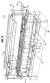
- Figure 1 is a side elevational view showing a circuit-like conveying apparatus which includes a first or lower treatment line, a second or upper drying line, lift mechanisms at the end of the lines and mechanisms for raising, lowering and moving work pieces in the lower treatment line.
- Figure 2 is an end elevational view taken along line 2-2 of Figure 1 showing the conveying apparatus frame, the upper and lower lines and a treatment tank positioned below the lower line.
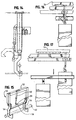
- Figure 3 is a diagrammatic and perspective view showing work pieces associated with a beam mechanism and positioned for lowering into a plurality of treatment tanks.
- Figure 4 is an end elevational view of a portion of the apparatus as seen in Figure 2 showing a work piece positioned for lowering into a treatment tank.
- Figure 5 is a view similar to Figure 3 showing the support beam lowered and work pieces lowered into a plurality of treatment tanks.
- Figure 6 is a view similar to Figure 4 showing a work piece lowered into a treatment tank.
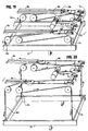
- Figure 7 is a view similar to Figure 5 showing the work pieces in the tanks and the rearward movement of the support beam.
- Figure 8 is a view similar to Figure 6 showing a work piece supported at the top of the tank and the support beam free to move rearwardly.
- Figure 9 is a perspective view of a fragment of the beam, hanger and tank showing the support beam moved downwardly and out of engagement with the hanger mechanism.
- Figure 10 is a perspective similar to Figure 7 showing the support beam raised and the work pieces raised from the tank and the beam positioned to receive a new work piece.
- Figure 11 is a perspective view similar to Figure 10 showing the support beam and work piece being moved forwardly so as to index the system forwardly one unit.
- Figure 12 is a perspective and diagrammatic view of a circuit-like conveying apparatus as in Figure 1 and showing the travel and hoist mechanism for moving the support beam and lift mechanisms at the end of the conveyor lines.
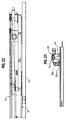
- Figure 13 is a side elevational view of a portion of the lower conveyor showing a hook mechanism for preventing the lowering of a work piece.
- Figure 14 is a side elevational view showing a piston-and-cylinder apparatus for operating the hook mechanism.
- Figure 15 is a perspective view showing the book mechanism.
- Figure 16 is side elevational view showing the hook mechanism grasping a work piece.
- Figure 17 is a side elevational view showing the hook mechanism in an operative position to restrain a first work piece and a second work piece in a lowered position.
- Figure 18 is an exploded perspective view showing the support beam and the travel and hoist mechanisms for causing the beam to index one station and for raising and lowering the beam relative to the frame.
- Figure 19 is a diagrammatic and perspective view showing a pulley and cable system for operating the hoist mechanism and a chain system for raising and lowering the beam.
- Figure 20 is similar to Figure 19 but with the hoist mechanism and beam in an extended position.
- Figure 21 is a plan view showing the travel and hoist mechanisms.
- Figure 22 is an elevational view showing the travel and hoist mechanisms connected to the beam and taken along line 22-22 of Figure 21.
- Figure 23 is a side elevational view of a traveler mechanism and taken generally along lines 23-23 of Figure 21.
- Figure 24 is a perspective view of a lift mechanism whereby work pieces can be retrieved from one conveyor and moved to a second conveyor.
- Figure 25 shows an arm and a saddle mechanism carried by the lift mechanism for engaging, supporting and moving a work piece and is taken along line 25-25 of Figure 24.
- Figure 26 is an end elevational view taken along line 26-26 of Figure 24 showing an arm or rail associated with the lift mechanism.
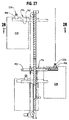
- Figure 27 is a side elevational view of the lift mechanism showing an arm with a work piece in various positions.
- Figure 28 is a plan-style view taken along line 28-28 of Figure 27.
-
- Referring now to Figure 1, there is shown a circuit-like conveying
system 10 generally which includes a lower ortreatment conveying line 12 generally, a lift ortransfer mechanism 14 positioned at the end of the lower treatment line to retrieve work pieces therefrom. An upper or drying conveyingline 16 is provided to receive treated work pieces from the lift ortransfer mechanism 14. Asecond lift mechanism 18 is positioned at the end of the dryingline 16 to retrieve dried work pieces therefrom and transfer those work pieces to a remote conveyor 20 (see Fig. 12). Untreated work pieces can be moved from theremote conveyor 20 to the entrance for thelower conveyor line 12. The work pieces are supported on awalking beam assembly 22 which is suspended from a hoistmechanism 24 which cooperates with atravel mechanism 26 that can be indexed forwardly one treatment station or backwardly one treatment station. - The
walking beam assembly 22, the hoistmechanism 24 and thetravel mechanism 26 are interconnected, interrelated and work together to transport, raise and lower work pieces. However, in the description herein theassembly 22 andmechanisms - The conveying
system 10 includes astationary support frame 28 which supports the lower conveyingline 12, the upper conveyingline 16, the hoistmechanism 24 and thetravel mechanism 26. As seen in Figure 2, a work piece such as 30 is positioned above thetreatment tank 32 for lowering into thetank 32 and subsequent treatment. It will also be appreciated that the circuit-like conveyingsystem 10 has depth or is three dimensional and accommodates wide work pieces such as 30. It is also seen that theframe 28 spans a treatment tank such as 32. - The operation of the
walking beam assembly 22 with respect to the work pieces and the hoist and travel operation is best seen in Figures 3-11 inclusive. Referring to Figs. 3, 5, 7, 10 and 11, thebeam assembly 22 includes a pair of spaced rails 22A and 22B. Associated with each rail are L-shaped hanger engaging members such as 34. Thebeam assembly 22 is raised and lowered by a plurality of chains such as 36. A work piece hanger such as 38 is arranged to support a dependingwork piece 40 and to engage the hanger engaging member such as 34. As seen in Figure 3 work pieces such as 40, 42 and 44 can be suspended from thebeam assembly 22 over tanks such as 46, 48 and 50. Referring to Figure 5, thebeam assembly 22 is lowered and thework pieces tanks - Then the
beam 22 is no longer engaged with the hangers and can be moved rearwardly one station as suggested in Figure 7. Then referring to Figure 10, thebeam 22 is raised and as it is raised it engages the hangers forwork pieces beam assembly 22 can be moved forwardly as in Figure 11 thereby indexing the work pieces one station forwardly. It will be noted that each station is spaced the same distance from an adjacent station. - Referring now to Figure 4, the
hanger 38 supporting thework piece 40 and hanger engagingmember bracket 34 are seen. In Figure 6 thehanger 38 is lowered to rest on the edge of the tank such as 46 and thehanger engaging member 34 is shown in engagement with the hanger and thework piece 40 is shown there below. As seen in Figure 8, thehanger engaging member 34 is positioned below and disengaged from thehanger 38 and is in position to be moved rearwardly with respect to the tank. - Referring to Figure 9, the
hanger 38 is shown as a square tube and thehanger engaging member 34 includes an angle iron 34A which is positioned to engage thehanger 38 and support the same. It is seen that based upon the movement of thebeam 22 downwardly, rearwardly, upwardly and forwardly the work pieces are moved in a rectangular pattern so as to move the work piece from one tank to another. - Figure 12 shows the entire circuit-like conveying
apparatus 10 in a diagrammatic fashion. There theremote conveyor 20 and thelift mechanism 18 are shown whereby an untreated work piece can be removed from theconveyor 20, delivered to thelower conveyor line 12 onto thebeam assembly 22 so as to be moved to the treatment tanks, then moved to the end of theconveyor 12 where thetransfer mechanism 14 can retrieve the work piece and move it upwardly to the drying orupper conveyor 16. Theupper conveyor 16 is a chain-like conveyor line that is positioned within an oven so as to form a drying line. Due to the heat to which the chain is exposed, the chain may lengthen and a take-up or tightening mechanism is provided within the oven so as to adjust the chain. - Sometimes, it is desirable to prevent a work piece from being immersed or dipped in a particular tank. A
hook assembly 50 is provided that is secured to astationary structure 51 secured to the frame 28 (See Figs. 1 and 13-17). The hook assembly includes an invertedU-shaped frame 52 that is secured to thestationary structure 51, two hingedly connected dependinghooks actuator bar 58 with an outwardly extendingarm 59 that connects thehooks pneumatic cylinder 60 is connected at one end to theframe section 52 and at the other end to theactuator bar 58 via thearm 59. By retracting the piston the bar is rotated and thehooks - The interrelations and interconnections of the travel and hoist
mechanisms beam assembly 22 are seen in Figure 18-23 inclusive. For purposes of description these mechanisms and assemblies have been described separately. - Referring first to Figure 18 the
stationary frame 28 includes an end section such as 70 and a pair of rails 72A and 72B. Thetravel mechanism 26 and hoistmechanism 24 are associated with theframe 28. Thebeam assembly 22 which supports the various hangers from the hoist mechanism by a plurality of spaced chains such as 74 and 76 and the previously identifiedchain 36. The chains are spaced along the length of the beam so as to evenly raise and lower the beant The chains are vertically orientated but trained about a plurality of vertically orientated sprockets such as 78 and 80 which are secured to thetravel frame 82 and rotate about a horizontal axis. The chains such as 74 and 76 are trained about the sprockets and are secured at their end to thepull rods pull rods spool 88 about which cables such as 90 and 92 are trained. A cable such as 90 passes through a set of pullies which permit it to retract the pull rods such as 86. Those pullies include the horizontally arrangedpulley 94, thepulley 96 and thepulley 98. It will be noted that the end of thecable 90 is grounded or secured to theframe 82 at apoint 100 similarly thepullies cables drum 88 thepull rods frame assembly 22 upwardly through the action of thechains frame 22 is shown in a lower position in Figure 20 in which thedrum 88 is reversed and the weight of theframe 22 tends to pull the frame downwardly and coacts with thepull rods chains spool 88,cables rollers grounding position 100 can also be seen in Figure 21. - Referring to Figure 22 the hoist
mechanism 24, thetravel mechanism 26 and thebeam assembly 22 is seen in elevational view and thebeam assembly 22 is in the upper position. As indicated above theentire beam assembly 22 and take up apparatus can be indexed one station forwardly or one station rearwardly so as to remove the work pieces from a first tank, raise them and move them to a second tank and then lower them. Referring to Figure 18, horizontal movement of thebeam assembly 22 is controlled by thetravel motor 110 drive shafts such as 112 stops 114 and 116 and the traveler or drivemechanism 118 generally(which is also seen in Figure 23). Fundamentally thetraveler 118 moves back and forth between thestops chain 120. It is seen that with the respect to the traveler movement thechain 120 is trained about anidler sprocket 122, a drivensprocket 124 and anotheridler sprocket 126. This themotor 110 rotates thedrive shaft 112 which causes thesprocket 124 to rotate. Thechain 120 is drawn beneath theidler sprocket 122 over thedrive sprocket 124 and beneath theidler sprocket 126 to cause thetraveler mechanism 118 to move toward one of thestops mechanism 24 similarly moves and so does thewalking beam assembly 22. The mechanism is then reversed and the walking beam is moved to the other end atstop 114. At that point thebeam 22 may be raised so as to lift the appropriate hangers and this the work pieces have been indexed or moved one station forwardly. - The transfer or lift mechanism can be seen in Figures 24-28 inclusive. However reference is made to Figure 12 where the
lift mechanisms lift mechanism 14 from the end of thelower line 12 to theline 16. Other lift mechanism can move dried work pieces from theupper line 16 to theremote conveyor 20 and from theremote conveyor 20 untreated pieces can be removed and delivered to thelower conveyor 12. - Referring now to Figure 24, a
lift mechanism 150 generally is shown. The lift includes a pair ofside posts cross members carrier 160 generally which can be moved vertically upwardly or downwardly in the larger frame. A pair ofarm assemblies carrier 160. Thecarrier 160 includes anupper cross member 166 and alower cross member 168. A pair ofvertical members cross members posts - The
carrier 160 is raised or lowered by a driven chain and counter weight mechanism. Thedrive motor 174 is connected via a shaft such as 176 tochain drive sprockets idler sprockets Drive chains carrier 160 by a bar such as 189. Thechain 186 is also connected to thecounter weight 190 but on the opposite side of the chain. Thus themotor 174 can drive the chain so that thecounter weight 190 moves upwardly and thecarrier 160 viabar 189 descends. If themotor 174 is reversed thecounter weight 190 is moved downwardly and thecarrier 160 is moved upwardly. Each of thearms like members top cross member 166 bybrackets rail 196 as seen in Figure 26. On each telescoping section such as 194 a hanger supporting saddle such as 198 or 199 is mounted. Thecarrier motor 200 andcarrier drive shafts carrier chains carrier cross member 166 is spaced above the connection of the arm to the carrier so as to permit thesaddle 198 to move thereunder. Moreover, the entire carrier is sized so as to permit clearance of a work piece suspended from saddles such as 198 and 199. Thecarrier chain 212 is connected to thetelescoping section 194 by apinion 213 andrack 214 which cooperate to cause the arm to move laterally inwardly and outwardly. - The
saddle 198 is connected to one end of thetelescoping section cable 216. Thecable 216 is trained about the idler 218 and secured to the telescoping section at anend 220. Thesaddle 198 is also connected to a secondtelescoping section cable 222 which is trained about aidler 224 and connected to the telescoping section atend 226. Thus as the arm moves from one side of the carrier to the other side of the carrier it will be seen that the saddle will move relative to thetelescoping section 194 and from one side of the carrier to the other side of thecarrier 160. This is seen in Figure 27 where thestationary arm 192 and thetelescoping arm 194 are shown. In this situation a saddle such as 198 is shown supporting a hanger such as 226 and work piece such as 228. It will be appreciated that thetelescoping section 194 of the arm as well as thehanger 226 andwork piece 228 is moved from one side of thepost 152 andcarrier 160 to the other side (i.e. left to right or vise versa). It is seen that in Figure 27 the arm can be moved to a lower position or raised to an upper position and thesaddle 198,hanger 226 andwork piece 228 can move accordingly. - In operation an untreated work piece is delivered on a
remote conveyor 20 so that a lift mechanism such as 18 can position a telescoping section such as 194 and hanger receiving saddles such as 198 and 199 under the hanger for the work piece and thus remove the work piece from the remote conveyor. The hanger rests on the saddles and the section is retracted under the action of thedrive motor 200. The telescoping sections of the arms are moved to the other side of the lift and in position to be delivered to the treatment conveyor line such as 12. There the hanger and work piece are deposited on the hanger engaging bracket such as 34 associated with thebeam 22 and the untreated pieces are added to the conveyor and moved as shown in Figs. 3, 5, 7, 10 and 11. The hoist andtravel mechanism lift mechanism 14 is provided and arms on the lift mechanism are extended and engage the hanger on the appropriate saddles. The arm is then retracted and lifted to the second line such as 16. There the arms extend and the hanger is deposited on theline 16. The treated piece is moved along the second or drying line to its exit end. There thelift mechanism 18 extends the arms and engages the hanger using the saddles. The arms are retracted, moved to a lower position, and caused to move to the other side of the lift mechanism and the hanger and work piece are deposited on theremote conveyor 20. The cycle is then repeated. It will be appreciated the appropriate controls are provided for the operation of the system. - Numerous changes can be made to the embodiment disclosed herein without departing from the spirit and scope of this invention.
Claims (15)
- A conveyor apparatus for the simultaneous and discontinuous movement of a plurality of work pieces to and between a plurality of treatment stations, said apparatus including:an elongated and stationary structural frame having an entrance end and an exit end;a plurality of treatment stations positioned along the length of the frame and in spaced relation thereto;a travel mechanism carried on the frame and moveable relative to the frame between adjacent treatment stations;a hoist mechanism carried on the travel mechanism and having retractable and extendable members; andan elongated beam which extends along the frame, which is connected to the hoist mechanism by the retractable and extendable members and which is constructed for movement between a lower position and an upper position and to releasably support each of a plurality of work pieces;so that the beam can be lowered for the work pieces to be treated, moved one station towards the entrance end, raised and moved one station toward the exit end so as to move the work pieces forwardly one station.
- An apparatus as in claim 1 wherein a hook assembly is mounted to the structural frame for engaging a work piece and to prevent the work piece from being lowered with other work pieces on the beam, said hook assembly including a bracket mounted to the frame, a pair of hook members hingedly mounted to the bracket and an actuator for moving the hook members between a grasping position and a non-grasping position.
- An apparatus as in claim 1 wherein said structural frame includes spaced stop members for limiting movement of the travel mechanism, and said travel mechanism includes a drive assembly for causing the travel mechanism to move between the stop members.
- An apparatus as in claim 3 wherein the drive assembly includes a traveler mechanism which includes a chain which extends between stop members, a drive sprocket for engaging the chain, a drive motor for rotating the drive sprocket and causing the travel mechanism to move along the chain between stop members.
- An apparatus as in claim 1 whereinthe retractable and extendable members include a pair of elongated pull rods each extending along the frame, spaced and substantially parallel to each other,a spool member secured to the travel mechanism, anda pulley and cable system connected to the spool member and to each of the pull rods so that winding of the cable about the spool causes the pull rods to move in one direction and unwinding permits the pull rods to move in the opposite direction.
- An apparatus as in claim 5 whereina plurality of sprockets are mounted to the travel mechanism, anda plurality of support chains are provided, each connected at one end to the elongated beam and at the other end to a pull rod and each trained about a sprocket so that the beam is raised or lowered by movement of the pulls rods.
- An apparatus as in claim 1 wherein each beam includes work piece hangers or grasping elements for supporting a work piece and for releasing a work piece for treatment.
- A transfer or lift apparatus for retrieving a work piece on a hanger from a first position and transporting the work piece to a second position, said apparatus including:a substantially vertical frame-like structure;a carrier assently mounted in the frame-like structure for movement upwardly and downwardly in the frame-like structure and including a pair of generally horizontally positioned arm assemblies mounted to the carrier, each of said arm assemblies including a horizontally extendable and retractable section for movement toward and away from the carrier assembly; anda work piece grasping structure mounted to the extendable and retractable section of said arm for movement with the arm to a position toward the end thereof when the arm extended from the carrier.
- An apparatus as in claim 8 wherein there is provided a drive assembly associated with the frame-like structure and carrier assembly for moving the carrier assembly upwardly or downwardly in the frame-like structure.
- An apparatus as in claim 9 wherein the drive assembly includes a drive motor, a drive sprocket connected to the drive motor for rotation by the drive motor, and a drive chain arranged for engagement by the sprocket and connected to the carrier assently for movement of the carrier assembly.
- An apparatus as in claim 9 wherein there is provided a counterweight connected to the drive chain for cooperation in moving the carrier assembly.
- An apparatus as in claim 10 wherein each of said arm assemblies include a stationary portion mounted to the carrier and said horizontally extendable or retractable section telescopically engages said stationary section for movement relative to the stationary section, and a hanger grasping saddle member moveably mounted on the telescoping section.
- An apparatus as in claim 14 wherein the hanger grasping section is constructed to move said telescoping section in relation to movement of the telescoping section.
- An apparatus as in claim 15 wherein the telescoping section includes a rack-like gear and a rotatable drive sprocket is provided and engages the rack-like gear so as to move the telescoping section upon rotation of sprocket.
- A circuit-like conveyor system which includes:a lower conveyor line having an entrance and an exit end;a first lift mechanism positioned adjacent the exit end of the lower line;an upper conveyor line spaced from the lower line and having an entrance end and an exit end, with the first lift mechanism positioned adjacent the entrance end of the upper conveyor line;a second lift mechanism positioned adjacent the exit end of the upper line and the entrance end of the lower line;and constructed for the simultaneous and discontinuous movement of a plurality of work pieces to and between a plurality of treatment stations:an elongated and stationary frame;said plurality of treatment stations positioned in spaced relation to the frame; and said lower conveyor line;a travel mechanism carried on the frame and movable relative to the frame between adjacent treatment stations;a hoist mechanism carried on the travel mechanism and having retractable and extendable supports;an elongated beam which extends along the frame and which is connected to the hoist mechanism by the retractable and extendable supports and which is constructed for movement between a lower position and an upper position and to releasably engage each of a plurality of work pieces; and which is constructed for movement toward the entrance end or toward the exit end of the lower conveyor so that the beam can be lowered and work pieces delivered to the treatment stations; moved one station toward the entrance end of the lower conveyor, raised, and moved one station toward the exit end so as to move the work pieces forwardly one station; and
wherein each of the lift mechanisms is constructed to retrieve a work piece on a hanger from a first position and transport the work piece to a second vertically different position, and each mechanism includes:a substantially vertical frame-like structure;a carrier assently mounted in the frame-like structure for movement upwardly and downwardly and includes a pair of generally horizontally positioned arm assemblies mounted to the carrier, each of said arms including a section which is horizontally extendable and retractable for movement toward and away from the carrier assembly; anda work piece receiving structure mounted to the extendable and retractable portion of each arm for movement with the arm to a position toward the end thereof when the arm is extended from the carrier.
Applications Claiming Priority (2)
| Application Number | Priority Date | Filing Date | Title |
|---|---|---|---|
| US307546 | 1981-10-01 | ||
| US09/307,546 US6253907B1 (en) | 1999-05-07 | 1999-05-07 | Conveying system for work pieces |
Publications (2)
| Publication Number | Publication Date |
|---|---|
| EP1050495A2 true EP1050495A2 (en) | 2000-11-08 |
| EP1050495A3 EP1050495A3 (en) | 2004-03-31 |
Family
ID=23190218
Family Applications (1)
| Application Number | Title | Priority Date | Filing Date |
|---|---|---|---|
| EP00301939A Withdrawn EP1050495A3 (en) | 1999-05-07 | 2000-03-09 | Conveying system for work pieces |
Country Status (3)
| Country | Link |
|---|---|
| US (2) | US6253907B1 (en) |
| EP (1) | EP1050495A3 (en) |
| CA (1) | CA2302069C (en) |
Cited By (4)
| Publication number | Priority date | Publication date | Assignee | Title |
|---|---|---|---|---|
| US6699329B2 (en) | 2001-05-25 | 2004-03-02 | George Koch Sons, Llc | Coating and curing system |
| EP1849890A1 (en) * | 2006-04-28 | 2007-10-31 | Wolf-Dieter Franz | Galvanic plant with conveying device for the movement of the rack |
| WO2009095152A1 (en) * | 2008-01-29 | 2009-08-06 | Volkswagen Aktiengesellschaft | Treatment system for the surface treatment of items, particularly vehicle bodies |
| CN106516633A (en) * | 2016-12-09 | 2017-03-22 | 广东天机工业智能系统有限公司 | Circulating production line |
Families Citing this family (26)
| Publication number | Priority date | Publication date | Assignee | Title |
|---|---|---|---|---|
| US6575177B1 (en) * | 1999-04-27 | 2003-06-10 | Applied Materials Inc. | Semiconductor substrate cleaning system |
| DE10039062B4 (en) * | 2000-08-10 | 2007-02-01 | Schuler Pressen Gmbh & Co. Kg | Transfer press and a device for loading or. Unloading workpieces |
| US6634484B2 (en) * | 2001-04-26 | 2003-10-21 | Honda Of Canada Mfg., A Division Of Honda Canada Inc. | Transfer and tilt apparatus |
| US20050279973A1 (en) * | 2004-03-09 | 2005-12-22 | Rea Jared A | Luggage cart vertical reciprocating conveyor |
| DE102004025525B3 (en) * | 2004-05-25 | 2005-12-08 | Eisenmann Maschinenbau Gmbh & Co. Kg | Method and device for drying objects, in particular painted vehicle bodies |
| US7097023B1 (en) * | 2004-07-30 | 2006-08-29 | Chun-Liang Chen | Finished product receiving unit of a corrugated metal sheet member making machine |
| US6983837B1 (en) * | 2004-07-30 | 2006-01-10 | Chun-Liang Chen | Finished product receiving unit used in a corrugated metal sheet member making machine |
| US20060068094A1 (en) * | 2004-09-29 | 2006-03-30 | Cole David J | Production paint shop design |
| US7534297B2 (en) * | 2005-04-19 | 2009-05-19 | The Boeing Company | Single item workflow manufacturing system and method |
| KR100969122B1 (en) * | 2007-12-14 | 2010-07-09 | 현대자동차주식회사 | Automatic transfer device for tire |
| US20090248190A1 (en) * | 2008-03-28 | 2009-10-01 | Spangler John M | Portable modular manufacturing system |
| US20100008749A1 (en) * | 2008-07-08 | 2010-01-14 | Caterpillar Inc. | Modular paint line including an immersion station |
| US10980925B1 (en) | 2008-10-14 | 2021-04-20 | A Hoyos Llc | High definition liposculpture |
| KR101063495B1 (en) * | 2009-06-15 | 2011-09-07 | 현대자동차주식회사 | Traverse device |
| US20140046471A1 (en) * | 2012-08-10 | 2014-02-13 | Globe Machine Manufacturing Company | Robotic scanning and processing systems and method |
| US9123196B1 (en) * | 2012-09-10 | 2015-09-01 | Haytham Salem | Rotating sandwich dispenser assembly |
| US9347603B2 (en) | 2013-06-20 | 2016-05-24 | Taggart Global, Llc | Counterweight hoisting apparatus |
| US10112221B1 (en) * | 2014-07-08 | 2018-10-30 | Michael P. Pedziwiatr | Ultrasonic processing apparatus and method |
| CN104528037B (en) * | 2014-12-26 | 2016-09-14 | 昆山精讯电子技术有限公司 | Liquid crystal module class wrapping pallet transporter |
| CN104528038B (en) * | 2014-12-26 | 2017-03-08 | 昆山精讯电子技术有限公司 | Liquid crystal module class wrapping device |
| CN109178817A (en) * | 2017-06-29 | 2019-01-11 | 无锡邦得机械有限公司 | Cleaning, drying line and its part transport device |
| USD883767S1 (en) | 2018-10-10 | 2020-05-12 | A Hoyos Llc | Handle |
| DE102019119053A1 (en) * | 2019-07-15 | 2021-01-21 | Eisenmann Se | Treatment installation for treating objects and methods for treating objects with such a treatment installation |
| US20210407824A1 (en) * | 2020-06-30 | 2021-12-30 | Applied Materials, Inc. | Spm processing of substrates |
| CN112591211B (en) * | 2020-11-25 | 2022-06-03 | 上海鹰卫精密机械有限公司 | Automatic feeding and discharging equipment for brick tower type sorting machine |
| CN114178230B (en) * | 2021-11-17 | 2023-06-16 | 贵州德科纳精密设备制造有限公司 | Automatic valve cleaning machine |
Citations (5)
| Publication number | Priority date | Publication date | Assignee | Title |
|---|---|---|---|---|
| US4597707A (en) * | 1984-08-17 | 1986-07-01 | General Machine Design, Inc. | Automatic operating palletizer |
| US4812211A (en) * | 1987-10-31 | 1989-03-14 | Hideyuki Sakai | Process and system for electrodeposition coating |
| GB2222573A (en) * | 1988-09-12 | 1990-03-14 | Fmc Corp | Robotic palletizer |
| DE4129829A1 (en) * | 1991-09-07 | 1993-03-11 | Brodhag Angelika | Automatic unloading appts. for bar-shaped food products - positions grippers on defined surfaces of bar, automatically removes bar from stack and places it at defined position |
| US5439015A (en) * | 1994-03-28 | 1995-08-08 | Shibano; Yoshihide | Cleaning apparatus |
Family Cites Families (15)
| Publication number | Priority date | Publication date | Assignee | Title |
|---|---|---|---|---|
| US3123197A (en) | 1964-03-03 | Transfer mechanism | ||
| US2789569A (en) | 1955-08-24 | 1957-04-23 | Udylite Corp | Plating machine |
| US2866565A (en) | 1957-04-02 | 1958-12-30 | Capitol Prod Corp | Proofer control system |
| US3024794A (en) * | 1959-05-19 | 1962-03-13 | Udylite Corp | Auxiliary work transfer mechanism for plating machines |
| CA675720A (en) * | 1959-08-13 | 1963-12-10 | Standard Telephones And Cables Mfg. Co. (Canada) Ltd. | Conveying system |
| US3082495A (en) * | 1960-01-15 | 1963-03-26 | Miller Engineering Corp | Conveyor transfer machine |
| US3381695A (en) * | 1966-08-03 | 1968-05-07 | Udylite Corp | Conveying apparatus |
| US3601134A (en) * | 1968-04-29 | 1971-08-24 | Clinton Supply Co | Automatic and manual plating machine |
| US3658197A (en) * | 1970-06-01 | 1972-04-25 | Lockheed Aircraft Corp | Programmable apparatus for conveying articles through successive process steps |
| US4749465A (en) | 1985-05-09 | 1988-06-07 | Seagate Technology | In-line disk sputtering system |
| US5012918A (en) | 1988-12-30 | 1991-05-07 | Therma-Tron-X, Inc. | Intermittent work conveying apparatus |
| US4942956A (en) | 1988-12-30 | 1990-07-24 | Therma-Tron-X, Inc. | Part indexing and positioning apparatus |
| US5452981A (en) * | 1991-03-06 | 1995-09-26 | Leland D. Blatt | Automatic tool changer |
| US5483876A (en) * | 1993-12-21 | 1996-01-16 | Trantek, Incorporated | Workpart transfer mechanism for stamping press |
| US5449268A (en) * | 1994-04-04 | 1995-09-12 | Western Atlas, Inc. | Variable speed drive mechanism with dwell |
-
1999
- 1999-05-07 US US09/307,546 patent/US6253907B1/en not_active Expired - Fee Related
-
2000
- 2000-03-09 EP EP00301939A patent/EP1050495A3/en not_active Withdrawn
- 2000-03-23 CA CA002302069A patent/CA2302069C/en not_active Expired - Fee Related
-
2001
- 2001-02-15 US US09/784,754 patent/US6345635B2/en not_active Expired - Fee Related
Patent Citations (5)
| Publication number | Priority date | Publication date | Assignee | Title |
|---|---|---|---|---|
| US4597707A (en) * | 1984-08-17 | 1986-07-01 | General Machine Design, Inc. | Automatic operating palletizer |
| US4812211A (en) * | 1987-10-31 | 1989-03-14 | Hideyuki Sakai | Process and system for electrodeposition coating |
| GB2222573A (en) * | 1988-09-12 | 1990-03-14 | Fmc Corp | Robotic palletizer |
| DE4129829A1 (en) * | 1991-09-07 | 1993-03-11 | Brodhag Angelika | Automatic unloading appts. for bar-shaped food products - positions grippers on defined surfaces of bar, automatically removes bar from stack and places it at defined position |
| US5439015A (en) * | 1994-03-28 | 1995-08-08 | Shibano; Yoshihide | Cleaning apparatus |
Cited By (6)
| Publication number | Priority date | Publication date | Assignee | Title |
|---|---|---|---|---|
| US6699329B2 (en) | 2001-05-25 | 2004-03-02 | George Koch Sons, Llc | Coating and curing system |
| EP1849890A1 (en) * | 2006-04-28 | 2007-10-31 | Wolf-Dieter Franz | Galvanic plant with conveying device for the movement of the rack |
| WO2009095152A1 (en) * | 2008-01-29 | 2009-08-06 | Volkswagen Aktiengesellschaft | Treatment system for the surface treatment of items, particularly vehicle bodies |
| US8469042B2 (en) | 2008-01-29 | 2013-06-25 | Volkswagen Aktiengesellschaft | Treatment system and method for the surface treatment of workpieces, particularly vehicle bodies |
| CN106516633A (en) * | 2016-12-09 | 2017-03-22 | 广东天机工业智能系统有限公司 | Circulating production line |
| CN106516633B (en) * | 2016-12-09 | 2019-06-21 | 广东天机工业智能系统有限公司 | Circulating production line |
Also Published As
| Publication number | Publication date |
|---|---|
| CA2302069C (en) | 2005-02-01 |
| US20010010281A1 (en) | 2001-08-02 |
| US6345635B2 (en) | 2002-02-12 |
| EP1050495A3 (en) | 2004-03-31 |
| US6253907B1 (en) | 2001-07-03 |
| CA2302069A1 (en) | 2000-11-07 |
Similar Documents
| Publication | Publication Date | Title |
|---|---|---|
| US6253907B1 (en) | Conveying system for work pieces | |
| US4256222A (en) | Transfer conveyor for the transfer of piece goods from a first roller track conveyor to a second roller track conveyor | |
| DE3735607C1 (en) | Storage and retrieval device for feeding clothes storage installations | |
| CN207748446U (en) | A kind of horizontal spraying pretreatment of aluminium section bar and installation device | |
| US4252486A (en) | System for transferring and storing elongated elements | |
| US5108345A (en) | Apparatus and method for loading live fowl onto a conveyor | |
| US2944655A (en) | Apparatus for unloading articles from a moving conveyor | |
| CN109987390A (en) | A kind of horizontal spraying pretreatment of aluminum profile and installation device | |
| US3851778A (en) | Transport system for goods carriers | |
| CN110980380A (en) | Continuous blanking device for sheet product production | |
| US4756401A (en) | Load transfer apparatus for power-driven overhead conveyor | |
| CN215853951U (en) | Bent block stacking device | |
| US2893573A (en) | Piler mechanism for metal sheets | |
| CN109430181B (en) | Cluster feeding system for silkworm tray | |
| JPH02150233A (en) | Method and device for stripping skin of slaughtered body | |
| CN212831047U (en) | Loading and unloading device of hanging assembly line | |
| US6048157A (en) | Turkey coop unloading apparatus and method | |
| CN210418272U (en) | Vertical conveying device and conveying system | |
| US4183514A (en) | System for spreading flexible material | |
| JPS6019602A (en) | Transferring apparatus for handling object | |
| US3599417A (en) | Method of placing packages of strand on a twist frame | |
| US3934736A (en) | Spring stacker | |
| US3982745A (en) | Fabric supplying and cutting system | |
| CN117163528A (en) | Steel pipe yardage roll transport buffer memory system | |
| RU2029639C1 (en) | Mobile aggregate for timber packs log by log disassembling and round timber sorting |
Legal Events
| Date | Code | Title | Description |
|---|---|---|---|
| PUAI | Public reference made under article 153(3) epc to a published international application that has entered the european phase |
Free format text: ORIGINAL CODE: 0009012 |
|
| 17P | Request for examination filed |
Effective date: 20000325 |
|
| AK | Designated contracting states |
Kind code of ref document: A2 Designated state(s): AT BE CH CY DE DK ES FI FR GB GR IE IT LI LU MC NL PT SE |
|
| AX | Request for extension of the european patent |
Free format text: AL;LT;LV;MK;RO;SI |
|
| RIC1 | Information provided on ipc code assigned before grant |
Ipc: 7B 65G 49/04 A |
|
| PUAL | Search report despatched |
Free format text: ORIGINAL CODE: 0009013 |
|
| RIC1 | Information provided on ipc code assigned before grant |
Ipc: 7B 65G 61/00 B Ipc: 7B 65G 49/04 A |
|
| AK | Designated contracting states |
Kind code of ref document: A3 Designated state(s): AT BE CH CY DE DK ES FI FR GB GR IE IT LI LU MC NL PT SE |
|
| AX | Request for extension of the european patent |
Extension state: AL LT LV MK RO SI |
|
| AKX | Designation fees paid |
Designated state(s): AT BE CH CY DE DK ES FI FR GB GR IE IT LI LU MC NL PT SE |
|
| STAA | Information on the status of an ep patent application or granted ep patent |
Free format text: STATUS: THE APPLICATION IS DEEMED TO BE WITHDRAWN |
|
| 18D | Application deemed to be withdrawn |
Effective date: 20041001 |