EP1049235A2 - Drive unit - Google Patents
Drive unit Download PDFInfo
- Publication number
- EP1049235A2 EP1049235A2 EP00108839A EP00108839A EP1049235A2 EP 1049235 A2 EP1049235 A2 EP 1049235A2 EP 00108839 A EP00108839 A EP 00108839A EP 00108839 A EP00108839 A EP 00108839A EP 1049235 A2 EP1049235 A2 EP 1049235A2
- Authority
- EP
- European Patent Office
- Prior art keywords
- drive unit
- chamber
- unit case
- partition wall
- inverter
- Prior art date
- Legal status (The legal status is an assumption and is not a legal conclusion. Google has not performed a legal analysis and makes no representation as to the accuracy of the status listed.)
- Granted
Links
Images


Classifications
-
- B—PERFORMING OPERATIONS; TRANSPORTING
- B60—VEHICLES IN GENERAL
- B60K—ARRANGEMENT OR MOUNTING OF PROPULSION UNITS OR OF TRANSMISSIONS IN VEHICLES; ARRANGEMENT OR MOUNTING OF PLURAL DIVERSE PRIME-MOVERS IN VEHICLES; AUXILIARY DRIVES FOR VEHICLES; INSTRUMENTATION OR DASHBOARDS FOR VEHICLES; ARRANGEMENTS IN CONNECTION WITH COOLING, AIR INTAKE, GAS EXHAUST OR FUEL SUPPLY OF PROPULSION UNITS IN VEHICLES
- B60K6/00—Arrangement or mounting of plural diverse prime-movers for mutual or common propulsion, e.g. hybrid propulsion systems comprising electric motors and internal combustion engines ; Control systems therefor, i.e. systems controlling two or more prime movers, or controlling one of these prime movers and any of the transmission, drive or drive units Informative references: mechanical gearings with secondary electric drive F16H3/72; arrangements for handling mechanical energy structurally associated with the dynamo-electric machine H02K7/00; machines comprising structurally interrelated motor and generator parts H02K51/00; dynamo-electric machines not otherwise provided for in H02K see H02K99/00
- B60K6/20—Arrangement or mounting of plural diverse prime-movers for mutual or common propulsion, e.g. hybrid propulsion systems comprising electric motors and internal combustion engines ; Control systems therefor, i.e. systems controlling two or more prime movers, or controlling one of these prime movers and any of the transmission, drive or drive units Informative references: mechanical gearings with secondary electric drive F16H3/72; arrangements for handling mechanical energy structurally associated with the dynamo-electric machine H02K7/00; machines comprising structurally interrelated motor and generator parts H02K51/00; dynamo-electric machines not otherwise provided for in H02K see H02K99/00 the prime-movers consisting of electric motors and internal combustion engines, e.g. HEVs
- B60K6/22—Arrangement or mounting of plural diverse prime-movers for mutual or common propulsion, e.g. hybrid propulsion systems comprising electric motors and internal combustion engines ; Control systems therefor, i.e. systems controlling two or more prime movers, or controlling one of these prime movers and any of the transmission, drive or drive units Informative references: mechanical gearings with secondary electric drive F16H3/72; arrangements for handling mechanical energy structurally associated with the dynamo-electric machine H02K7/00; machines comprising structurally interrelated motor and generator parts H02K51/00; dynamo-electric machines not otherwise provided for in H02K see H02K99/00 the prime-movers consisting of electric motors and internal combustion engines, e.g. HEVs characterised by apparatus, components or means specially adapted for HEVs
- B60K6/26—Arrangement or mounting of plural diverse prime-movers for mutual or common propulsion, e.g. hybrid propulsion systems comprising electric motors and internal combustion engines ; Control systems therefor, i.e. systems controlling two or more prime movers, or controlling one of these prime movers and any of the transmission, drive or drive units Informative references: mechanical gearings with secondary electric drive F16H3/72; arrangements for handling mechanical energy structurally associated with the dynamo-electric machine H02K7/00; machines comprising structurally interrelated motor and generator parts H02K51/00; dynamo-electric machines not otherwise provided for in H02K see H02K99/00 the prime-movers consisting of electric motors and internal combustion engines, e.g. HEVs characterised by apparatus, components or means specially adapted for HEVs characterised by the motors or the generators
-
- B—PERFORMING OPERATIONS; TRANSPORTING
- B60—VEHICLES IN GENERAL
- B60K—ARRANGEMENT OR MOUNTING OF PROPULSION UNITS OR OF TRANSMISSIONS IN VEHICLES; ARRANGEMENT OR MOUNTING OF PLURAL DIVERSE PRIME-MOVERS IN VEHICLES; AUXILIARY DRIVES FOR VEHICLES; INSTRUMENTATION OR DASHBOARDS FOR VEHICLES; ARRANGEMENTS IN CONNECTION WITH COOLING, AIR INTAKE, GAS EXHAUST OR FUEL SUPPLY OF PROPULSION UNITS IN VEHICLES
- B60K6/00—Arrangement or mounting of plural diverse prime-movers for mutual or common propulsion, e.g. hybrid propulsion systems comprising electric motors and internal combustion engines ; Control systems therefor, i.e. systems controlling two or more prime movers, or controlling one of these prime movers and any of the transmission, drive or drive units Informative references: mechanical gearings with secondary electric drive F16H3/72; arrangements for handling mechanical energy structurally associated with the dynamo-electric machine H02K7/00; machines comprising structurally interrelated motor and generator parts H02K51/00; dynamo-electric machines not otherwise provided for in H02K see H02K99/00
- B60K6/20—Arrangement or mounting of plural diverse prime-movers for mutual or common propulsion, e.g. hybrid propulsion systems comprising electric motors and internal combustion engines ; Control systems therefor, i.e. systems controlling two or more prime movers, or controlling one of these prime movers and any of the transmission, drive or drive units Informative references: mechanical gearings with secondary electric drive F16H3/72; arrangements for handling mechanical energy structurally associated with the dynamo-electric machine H02K7/00; machines comprising structurally interrelated motor and generator parts H02K51/00; dynamo-electric machines not otherwise provided for in H02K see H02K99/00 the prime-movers consisting of electric motors and internal combustion engines, e.g. HEVs
- B60K6/22—Arrangement or mounting of plural diverse prime-movers for mutual or common propulsion, e.g. hybrid propulsion systems comprising electric motors and internal combustion engines ; Control systems therefor, i.e. systems controlling two or more prime movers, or controlling one of these prime movers and any of the transmission, drive or drive units Informative references: mechanical gearings with secondary electric drive F16H3/72; arrangements for handling mechanical energy structurally associated with the dynamo-electric machine H02K7/00; machines comprising structurally interrelated motor and generator parts H02K51/00; dynamo-electric machines not otherwise provided for in H02K see H02K99/00 the prime-movers consisting of electric motors and internal combustion engines, e.g. HEVs characterised by apparatus, components or means specially adapted for HEVs
- B60K6/40—Arrangement or mounting of plural diverse prime-movers for mutual or common propulsion, e.g. hybrid propulsion systems comprising electric motors and internal combustion engines ; Control systems therefor, i.e. systems controlling two or more prime movers, or controlling one of these prime movers and any of the transmission, drive or drive units Informative references: mechanical gearings with secondary electric drive F16H3/72; arrangements for handling mechanical energy structurally associated with the dynamo-electric machine H02K7/00; machines comprising structurally interrelated motor and generator parts H02K51/00; dynamo-electric machines not otherwise provided for in H02K see H02K99/00 the prime-movers consisting of electric motors and internal combustion engines, e.g. HEVs characterised by apparatus, components or means specially adapted for HEVs characterised by the assembly or relative disposition of components
- B60K6/405—Housings
-
- B—PERFORMING OPERATIONS; TRANSPORTING
- B60—VEHICLES IN GENERAL
- B60K—ARRANGEMENT OR MOUNTING OF PROPULSION UNITS OR OF TRANSMISSIONS IN VEHICLES; ARRANGEMENT OR MOUNTING OF PLURAL DIVERSE PRIME-MOVERS IN VEHICLES; AUXILIARY DRIVES FOR VEHICLES; INSTRUMENTATION OR DASHBOARDS FOR VEHICLES; ARRANGEMENTS IN CONNECTION WITH COOLING, AIR INTAKE, GAS EXHAUST OR FUEL SUPPLY OF PROPULSION UNITS IN VEHICLES
- B60K6/00—Arrangement or mounting of plural diverse prime-movers for mutual or common propulsion, e.g. hybrid propulsion systems comprising electric motors and internal combustion engines ; Control systems therefor, i.e. systems controlling two or more prime movers, or controlling one of these prime movers and any of the transmission, drive or drive units Informative references: mechanical gearings with secondary electric drive F16H3/72; arrangements for handling mechanical energy structurally associated with the dynamo-electric machine H02K7/00; machines comprising structurally interrelated motor and generator parts H02K51/00; dynamo-electric machines not otherwise provided for in H02K see H02K99/00
- B60K6/20—Arrangement or mounting of plural diverse prime-movers for mutual or common propulsion, e.g. hybrid propulsion systems comprising electric motors and internal combustion engines ; Control systems therefor, i.e. systems controlling two or more prime movers, or controlling one of these prime movers and any of the transmission, drive or drive units Informative references: mechanical gearings with secondary electric drive F16H3/72; arrangements for handling mechanical energy structurally associated with the dynamo-electric machine H02K7/00; machines comprising structurally interrelated motor and generator parts H02K51/00; dynamo-electric machines not otherwise provided for in H02K see H02K99/00 the prime-movers consisting of electric motors and internal combustion engines, e.g. HEVs
- B60K6/42—Arrangement or mounting of plural diverse prime-movers for mutual or common propulsion, e.g. hybrid propulsion systems comprising electric motors and internal combustion engines ; Control systems therefor, i.e. systems controlling two or more prime movers, or controlling one of these prime movers and any of the transmission, drive or drive units Informative references: mechanical gearings with secondary electric drive F16H3/72; arrangements for handling mechanical energy structurally associated with the dynamo-electric machine H02K7/00; machines comprising structurally interrelated motor and generator parts H02K51/00; dynamo-electric machines not otherwise provided for in H02K see H02K99/00 the prime-movers consisting of electric motors and internal combustion engines, e.g. HEVs characterised by the architecture of the hybrid electric vehicle
- B60K6/44—Series-parallel type
- B60K6/445—Differential gearing distribution type
-
- B—PERFORMING OPERATIONS; TRANSPORTING
- B60—VEHICLES IN GENERAL
- B60L—PROPULSION OF ELECTRICALLY-PROPELLED VEHICLES; SUPPLYING ELECTRIC POWER FOR AUXILIARY EQUIPMENT OF ELECTRICALLY-PROPELLED VEHICLES; ELECTRODYNAMIC BRAKE SYSTEMS FOR VEHICLES IN GENERAL; MAGNETIC SUSPENSION OR LEVITATION FOR VEHICLES; MONITORING OPERATING VARIABLES OF ELECTRICALLY-PROPELLED VEHICLES; ELECTRIC SAFETY DEVICES FOR ELECTRICALLY-PROPELLED VEHICLES
- B60L1/00—Supplying electric power to auxiliary equipment of vehicles
- B60L1/003—Supplying electric power to auxiliary equipment of vehicles to auxiliary motors, e.g. for pumps, compressors
-
- B—PERFORMING OPERATIONS; TRANSPORTING
- B60—VEHICLES IN GENERAL
- B60L—PROPULSION OF ELECTRICALLY-PROPELLED VEHICLES; SUPPLYING ELECTRIC POWER FOR AUXILIARY EQUIPMENT OF ELECTRICALLY-PROPELLED VEHICLES; ELECTRODYNAMIC BRAKE SYSTEMS FOR VEHICLES IN GENERAL; MAGNETIC SUSPENSION OR LEVITATION FOR VEHICLES; MONITORING OPERATING VARIABLES OF ELECTRICALLY-PROPELLED VEHICLES; ELECTRIC SAFETY DEVICES FOR ELECTRICALLY-PROPELLED VEHICLES
- B60L1/00—Supplying electric power to auxiliary equipment of vehicles
- B60L1/02—Supplying electric power to auxiliary equipment of vehicles to electric heating circuits
-
- B—PERFORMING OPERATIONS; TRANSPORTING
- B60—VEHICLES IN GENERAL
- B60L—PROPULSION OF ELECTRICALLY-PROPELLED VEHICLES; SUPPLYING ELECTRIC POWER FOR AUXILIARY EQUIPMENT OF ELECTRICALLY-PROPELLED VEHICLES; ELECTRODYNAMIC BRAKE SYSTEMS FOR VEHICLES IN GENERAL; MAGNETIC SUSPENSION OR LEVITATION FOR VEHICLES; MONITORING OPERATING VARIABLES OF ELECTRICALLY-PROPELLED VEHICLES; ELECTRIC SAFETY DEVICES FOR ELECTRICALLY-PROPELLED VEHICLES
- B60L15/00—Methods, circuits, or devices for controlling the traction-motor speed of electrically-propelled vehicles
- B60L15/007—Physical arrangements or structures of drive train converters specially adapted for the propulsion motors of electric vehicles
-
- B—PERFORMING OPERATIONS; TRANSPORTING
- B60—VEHICLES IN GENERAL
- B60L—PROPULSION OF ELECTRICALLY-PROPELLED VEHICLES; SUPPLYING ELECTRIC POWER FOR AUXILIARY EQUIPMENT OF ELECTRICALLY-PROPELLED VEHICLES; ELECTRODYNAMIC BRAKE SYSTEMS FOR VEHICLES IN GENERAL; MAGNETIC SUSPENSION OR LEVITATION FOR VEHICLES; MONITORING OPERATING VARIABLES OF ELECTRICALLY-PROPELLED VEHICLES; ELECTRIC SAFETY DEVICES FOR ELECTRICALLY-PROPELLED VEHICLES
- B60L15/00—Methods, circuits, or devices for controlling the traction-motor speed of electrically-propelled vehicles
- B60L15/20—Methods, circuits, or devices for controlling the traction-motor speed of electrically-propelled vehicles for control of the vehicle or its driving motor to achieve a desired performance, e.g. speed, torque, programmed variation of speed
-
- B—PERFORMING OPERATIONS; TRANSPORTING
- B60—VEHICLES IN GENERAL
- B60L—PROPULSION OF ELECTRICALLY-PROPELLED VEHICLES; SUPPLYING ELECTRIC POWER FOR AUXILIARY EQUIPMENT OF ELECTRICALLY-PROPELLED VEHICLES; ELECTRODYNAMIC BRAKE SYSTEMS FOR VEHICLES IN GENERAL; MAGNETIC SUSPENSION OR LEVITATION FOR VEHICLES; MONITORING OPERATING VARIABLES OF ELECTRICALLY-PROPELLED VEHICLES; ELECTRIC SAFETY DEVICES FOR ELECTRICALLY-PROPELLED VEHICLES
- B60L3/00—Electric devices on electrically-propelled vehicles for safety purposes; Monitoring operating variables, e.g. speed, deceleration or energy consumption
- B60L3/0023—Detecting, eliminating, remedying or compensating for drive train abnormalities, e.g. failures within the drive train
- B60L3/003—Detecting, eliminating, remedying or compensating for drive train abnormalities, e.g. failures within the drive train relating to inverters
-
- B—PERFORMING OPERATIONS; TRANSPORTING
- B60—VEHICLES IN GENERAL
- B60L—PROPULSION OF ELECTRICALLY-PROPELLED VEHICLES; SUPPLYING ELECTRIC POWER FOR AUXILIARY EQUIPMENT OF ELECTRICALLY-PROPELLED VEHICLES; ELECTRODYNAMIC BRAKE SYSTEMS FOR VEHICLES IN GENERAL; MAGNETIC SUSPENSION OR LEVITATION FOR VEHICLES; MONITORING OPERATING VARIABLES OF ELECTRICALLY-PROPELLED VEHICLES; ELECTRIC SAFETY DEVICES FOR ELECTRICALLY-PROPELLED VEHICLES
- B60L3/00—Electric devices on electrically-propelled vehicles for safety purposes; Monitoring operating variables, e.g. speed, deceleration or energy consumption
- B60L3/0023—Detecting, eliminating, remedying or compensating for drive train abnormalities, e.g. failures within the drive train
- B60L3/0061—Detecting, eliminating, remedying or compensating for drive train abnormalities, e.g. failures within the drive train relating to electrical machines
-
- B—PERFORMING OPERATIONS; TRANSPORTING
- B60—VEHICLES IN GENERAL
- B60L—PROPULSION OF ELECTRICALLY-PROPELLED VEHICLES; SUPPLYING ELECTRIC POWER FOR AUXILIARY EQUIPMENT OF ELECTRICALLY-PROPELLED VEHICLES; ELECTRODYNAMIC BRAKE SYSTEMS FOR VEHICLES IN GENERAL; MAGNETIC SUSPENSION OR LEVITATION FOR VEHICLES; MONITORING OPERATING VARIABLES OF ELECTRICALLY-PROPELLED VEHICLES; ELECTRIC SAFETY DEVICES FOR ELECTRICALLY-PROPELLED VEHICLES
- B60L50/00—Electric propulsion with power supplied within the vehicle
- B60L50/10—Electric propulsion with power supplied within the vehicle using propulsion power supplied by engine-driven generators, e.g. generators driven by combustion engines
- B60L50/16—Electric propulsion with power supplied within the vehicle using propulsion power supplied by engine-driven generators, e.g. generators driven by combustion engines with provision for separate direct mechanical propulsion
-
- B—PERFORMING OPERATIONS; TRANSPORTING
- B60—VEHICLES IN GENERAL
- B60L—PROPULSION OF ELECTRICALLY-PROPELLED VEHICLES; SUPPLYING ELECTRIC POWER FOR AUXILIARY EQUIPMENT OF ELECTRICALLY-PROPELLED VEHICLES; ELECTRODYNAMIC BRAKE SYSTEMS FOR VEHICLES IN GENERAL; MAGNETIC SUSPENSION OR LEVITATION FOR VEHICLES; MONITORING OPERATING VARIABLES OF ELECTRICALLY-PROPELLED VEHICLES; ELECTRIC SAFETY DEVICES FOR ELECTRICALLY-PROPELLED VEHICLES
- B60L50/00—Electric propulsion with power supplied within the vehicle
- B60L50/50—Electric propulsion with power supplied within the vehicle using propulsion power supplied by batteries or fuel cells
- B60L50/60—Electric propulsion with power supplied within the vehicle using propulsion power supplied by batteries or fuel cells using power supplied by batteries
- B60L50/61—Electric propulsion with power supplied within the vehicle using propulsion power supplied by batteries or fuel cells using power supplied by batteries by batteries charged by engine-driven generators, e.g. series hybrid electric vehicles
-
- B—PERFORMING OPERATIONS; TRANSPORTING
- B60—VEHICLES IN GENERAL
- B60W—CONJOINT CONTROL OF VEHICLE SUB-UNITS OF DIFFERENT TYPE OR DIFFERENT FUNCTION; CONTROL SYSTEMS SPECIALLY ADAPTED FOR HYBRID VEHICLES; ROAD VEHICLE DRIVE CONTROL SYSTEMS FOR PURPOSES NOT RELATED TO THE CONTROL OF A PARTICULAR SUB-UNIT
- B60W10/00—Conjoint control of vehicle sub-units of different type or different function
- B60W10/24—Conjoint control of vehicle sub-units of different type or different function including control of energy storage means
- B60W10/26—Conjoint control of vehicle sub-units of different type or different function including control of energy storage means for electrical energy, e.g. batteries or capacitors
-
- H—ELECTRICITY
- H02—GENERATION; CONVERSION OR DISTRIBUTION OF ELECTRIC POWER
- H02K—DYNAMO-ELECTRIC MACHINES
- H02K11/00—Structural association of dynamo-electric machines with electric components or with devices for shielding, monitoring or protection
- H02K11/30—Structural association with control circuits or drive circuits
- H02K11/33—Drive circuits, e.g. power electronics
-
- H—ELECTRICITY
- H02—GENERATION; CONVERSION OR DISTRIBUTION OF ELECTRIC POWER
- H02K—DYNAMO-ELECTRIC MACHINES
- H02K16/00—Machines with more than one rotor or stator
-
- H—ELECTRICITY
- H02—GENERATION; CONVERSION OR DISTRIBUTION OF ELECTRIC POWER
- H02K—DYNAMO-ELECTRIC MACHINES
- H02K7/00—Arrangements for handling mechanical energy structurally associated with dynamo-electric machines, e.g. structural association with mechanical driving motors or auxiliary dynamo-electric machines
- H02K7/10—Structural association with clutches, brakes, gears, pulleys or mechanical starters
- H02K7/116—Structural association with clutches, brakes, gears, pulleys or mechanical starters with gears
-
- H—ELECTRICITY
- H02—GENERATION; CONVERSION OR DISTRIBUTION OF ELECTRIC POWER
- H02K—DYNAMO-ELECTRIC MACHINES
- H02K9/00—Arrangements for cooling or ventilating
- H02K9/19—Arrangements for cooling or ventilating for machines with closed casing and closed-circuit cooling using a liquid cooling medium, e.g. oil
-
- B—PERFORMING OPERATIONS; TRANSPORTING
- B60—VEHICLES IN GENERAL
- B60K—ARRANGEMENT OR MOUNTING OF PROPULSION UNITS OR OF TRANSMISSIONS IN VEHICLES; ARRANGEMENT OR MOUNTING OF PLURAL DIVERSE PRIME-MOVERS IN VEHICLES; AUXILIARY DRIVES FOR VEHICLES; INSTRUMENTATION OR DASHBOARDS FOR VEHICLES; ARRANGEMENTS IN CONNECTION WITH COOLING, AIR INTAKE, GAS EXHAUST OR FUEL SUPPLY OF PROPULSION UNITS IN VEHICLES
- B60K1/00—Arrangement or mounting of electrical propulsion units
- B60K1/02—Arrangement or mounting of electrical propulsion units comprising more than one electric motor
-
- B—PERFORMING OPERATIONS; TRANSPORTING
- B60—VEHICLES IN GENERAL
- B60K—ARRANGEMENT OR MOUNTING OF PROPULSION UNITS OR OF TRANSMISSIONS IN VEHICLES; ARRANGEMENT OR MOUNTING OF PLURAL DIVERSE PRIME-MOVERS IN VEHICLES; AUXILIARY DRIVES FOR VEHICLES; INSTRUMENTATION OR DASHBOARDS FOR VEHICLES; ARRANGEMENTS IN CONNECTION WITH COOLING, AIR INTAKE, GAS EXHAUST OR FUEL SUPPLY OF PROPULSION UNITS IN VEHICLES
- B60K1/00—Arrangement or mounting of electrical propulsion units
- B60K2001/003—Arrangement or mounting of electrical propulsion units with means for cooling the electrical propulsion units
-
- B—PERFORMING OPERATIONS; TRANSPORTING
- B60—VEHICLES IN GENERAL
- B60L—PROPULSION OF ELECTRICALLY-PROPELLED VEHICLES; SUPPLYING ELECTRIC POWER FOR AUXILIARY EQUIPMENT OF ELECTRICALLY-PROPELLED VEHICLES; ELECTRODYNAMIC BRAKE SYSTEMS FOR VEHICLES IN GENERAL; MAGNETIC SUSPENSION OR LEVITATION FOR VEHICLES; MONITORING OPERATING VARIABLES OF ELECTRICALLY-PROPELLED VEHICLES; ELECTRIC SAFETY DEVICES FOR ELECTRICALLY-PROPELLED VEHICLES
- B60L2210/00—Converter types
- B60L2210/40—DC to AC converters
-
- B—PERFORMING OPERATIONS; TRANSPORTING
- B60—VEHICLES IN GENERAL
- B60L—PROPULSION OF ELECTRICALLY-PROPELLED VEHICLES; SUPPLYING ELECTRIC POWER FOR AUXILIARY EQUIPMENT OF ELECTRICALLY-PROPELLED VEHICLES; ELECTRODYNAMIC BRAKE SYSTEMS FOR VEHICLES IN GENERAL; MAGNETIC SUSPENSION OR LEVITATION FOR VEHICLES; MONITORING OPERATING VARIABLES OF ELECTRICALLY-PROPELLED VEHICLES; ELECTRIC SAFETY DEVICES FOR ELECTRICALLY-PROPELLED VEHICLES
- B60L2240/00—Control parameters of input or output; Target parameters
- B60L2240/10—Vehicle control parameters
- B60L2240/36—Temperature of vehicle components or parts
-
- B—PERFORMING OPERATIONS; TRANSPORTING
- B60—VEHICLES IN GENERAL
- B60L—PROPULSION OF ELECTRICALLY-PROPELLED VEHICLES; SUPPLYING ELECTRIC POWER FOR AUXILIARY EQUIPMENT OF ELECTRICALLY-PROPELLED VEHICLES; ELECTRODYNAMIC BRAKE SYSTEMS FOR VEHICLES IN GENERAL; MAGNETIC SUSPENSION OR LEVITATION FOR VEHICLES; MONITORING OPERATING VARIABLES OF ELECTRICALLY-PROPELLED VEHICLES; ELECTRIC SAFETY DEVICES FOR ELECTRICALLY-PROPELLED VEHICLES
- B60L2240/00—Control parameters of input or output; Target parameters
- B60L2240/40—Drive Train control parameters
- B60L2240/42—Drive Train control parameters related to electric machines
- B60L2240/421—Speed
-
- B—PERFORMING OPERATIONS; TRANSPORTING
- B60—VEHICLES IN GENERAL
- B60L—PROPULSION OF ELECTRICALLY-PROPELLED VEHICLES; SUPPLYING ELECTRIC POWER FOR AUXILIARY EQUIPMENT OF ELECTRICALLY-PROPELLED VEHICLES; ELECTRODYNAMIC BRAKE SYSTEMS FOR VEHICLES IN GENERAL; MAGNETIC SUSPENSION OR LEVITATION FOR VEHICLES; MONITORING OPERATING VARIABLES OF ELECTRICALLY-PROPELLED VEHICLES; ELECTRIC SAFETY DEVICES FOR ELECTRICALLY-PROPELLED VEHICLES
- B60L2240/00—Control parameters of input or output; Target parameters
- B60L2240/40—Drive Train control parameters
- B60L2240/42—Drive Train control parameters related to electric machines
- B60L2240/423—Torque
-
- B—PERFORMING OPERATIONS; TRANSPORTING
- B60—VEHICLES IN GENERAL
- B60L—PROPULSION OF ELECTRICALLY-PROPELLED VEHICLES; SUPPLYING ELECTRIC POWER FOR AUXILIARY EQUIPMENT OF ELECTRICALLY-PROPELLED VEHICLES; ELECTRODYNAMIC BRAKE SYSTEMS FOR VEHICLES IN GENERAL; MAGNETIC SUSPENSION OR LEVITATION FOR VEHICLES; MONITORING OPERATING VARIABLES OF ELECTRICALLY-PROPELLED VEHICLES; ELECTRIC SAFETY DEVICES FOR ELECTRICALLY-PROPELLED VEHICLES
- B60L2240/00—Control parameters of input or output; Target parameters
- B60L2240/40—Drive Train control parameters
- B60L2240/42—Drive Train control parameters related to electric machines
- B60L2240/425—Temperature
-
- B—PERFORMING OPERATIONS; TRANSPORTING
- B60—VEHICLES IN GENERAL
- B60L—PROPULSION OF ELECTRICALLY-PROPELLED VEHICLES; SUPPLYING ELECTRIC POWER FOR AUXILIARY EQUIPMENT OF ELECTRICALLY-PROPELLED VEHICLES; ELECTRODYNAMIC BRAKE SYSTEMS FOR VEHICLES IN GENERAL; MAGNETIC SUSPENSION OR LEVITATION FOR VEHICLES; MONITORING OPERATING VARIABLES OF ELECTRICALLY-PROPELLED VEHICLES; ELECTRIC SAFETY DEVICES FOR ELECTRICALLY-PROPELLED VEHICLES
- B60L2240/00—Control parameters of input or output; Target parameters
- B60L2240/40—Drive Train control parameters
- B60L2240/52—Drive Train control parameters related to converters
- B60L2240/525—Temperature of converter or components thereof
-
- F—MECHANICAL ENGINEERING; LIGHTING; HEATING; WEAPONS; BLASTING
- F01—MACHINES OR ENGINES IN GENERAL; ENGINE PLANTS IN GENERAL; STEAM ENGINES
- F01P—COOLING OF MACHINES OR ENGINES IN GENERAL; COOLING OF INTERNAL-COMBUSTION ENGINES
- F01P2050/00—Applications
- F01P2050/24—Hybrid vehicles
-
- F—MECHANICAL ENGINEERING; LIGHTING; HEATING; WEAPONS; BLASTING
- F01—MACHINES OR ENGINES IN GENERAL; ENGINE PLANTS IN GENERAL; STEAM ENGINES
- F01P—COOLING OF MACHINES OR ENGINES IN GENERAL; COOLING OF INTERNAL-COMBUSTION ENGINES
- F01P2050/00—Applications
- F01P2050/30—Circuit boards
-
- Y—GENERAL TAGGING OF NEW TECHNOLOGICAL DEVELOPMENTS; GENERAL TAGGING OF CROSS-SECTIONAL TECHNOLOGIES SPANNING OVER SEVERAL SECTIONS OF THE IPC; TECHNICAL SUBJECTS COVERED BY FORMER USPC CROSS-REFERENCE ART COLLECTIONS [XRACs] AND DIGESTS
- Y02—TECHNOLOGIES OR APPLICATIONS FOR MITIGATION OR ADAPTATION AGAINST CLIMATE CHANGE
- Y02T—CLIMATE CHANGE MITIGATION TECHNOLOGIES RELATED TO TRANSPORTATION
- Y02T10/00—Road transport of goods or passengers
- Y02T10/60—Other road transportation technologies with climate change mitigation effect
- Y02T10/62—Hybrid vehicles
-
- Y—GENERAL TAGGING OF NEW TECHNOLOGICAL DEVELOPMENTS; GENERAL TAGGING OF CROSS-SECTIONAL TECHNOLOGIES SPANNING OVER SEVERAL SECTIONS OF THE IPC; TECHNICAL SUBJECTS COVERED BY FORMER USPC CROSS-REFERENCE ART COLLECTIONS [XRACs] AND DIGESTS
- Y02—TECHNOLOGIES OR APPLICATIONS FOR MITIGATION OR ADAPTATION AGAINST CLIMATE CHANGE
- Y02T—CLIMATE CHANGE MITIGATION TECHNOLOGIES RELATED TO TRANSPORTATION
- Y02T10/00—Road transport of goods or passengers
- Y02T10/60—Other road transportation technologies with climate change mitigation effect
- Y02T10/64—Electric machine technologies in electromobility
-
- Y—GENERAL TAGGING OF NEW TECHNOLOGICAL DEVELOPMENTS; GENERAL TAGGING OF CROSS-SECTIONAL TECHNOLOGIES SPANNING OVER SEVERAL SECTIONS OF THE IPC; TECHNICAL SUBJECTS COVERED BY FORMER USPC CROSS-REFERENCE ART COLLECTIONS [XRACs] AND DIGESTS
- Y02—TECHNOLOGIES OR APPLICATIONS FOR MITIGATION OR ADAPTATION AGAINST CLIMATE CHANGE
- Y02T—CLIMATE CHANGE MITIGATION TECHNOLOGIES RELATED TO TRANSPORTATION
- Y02T10/00—Road transport of goods or passengers
- Y02T10/60—Other road transportation technologies with climate change mitigation effect
- Y02T10/70—Energy storage systems for electromobility, e.g. batteries
-
- Y—GENERAL TAGGING OF NEW TECHNOLOGICAL DEVELOPMENTS; GENERAL TAGGING OF CROSS-SECTIONAL TECHNOLOGIES SPANNING OVER SEVERAL SECTIONS OF THE IPC; TECHNICAL SUBJECTS COVERED BY FORMER USPC CROSS-REFERENCE ART COLLECTIONS [XRACs] AND DIGESTS
- Y02—TECHNOLOGIES OR APPLICATIONS FOR MITIGATION OR ADAPTATION AGAINST CLIMATE CHANGE
- Y02T—CLIMATE CHANGE MITIGATION TECHNOLOGIES RELATED TO TRANSPORTATION
- Y02T10/00—Road transport of goods or passengers
- Y02T10/60—Other road transportation technologies with climate change mitigation effect
- Y02T10/7072—Electromobility specific charging systems or methods for batteries, ultracapacitors, supercapacitors or double-layer capacitors
-
- Y—GENERAL TAGGING OF NEW TECHNOLOGICAL DEVELOPMENTS; GENERAL TAGGING OF CROSS-SECTIONAL TECHNOLOGIES SPANNING OVER SEVERAL SECTIONS OF THE IPC; TECHNICAL SUBJECTS COVERED BY FORMER USPC CROSS-REFERENCE ART COLLECTIONS [XRACs] AND DIGESTS
- Y02—TECHNOLOGIES OR APPLICATIONS FOR MITIGATION OR ADAPTATION AGAINST CLIMATE CHANGE
- Y02T—CLIMATE CHANGE MITIGATION TECHNOLOGIES RELATED TO TRANSPORTATION
- Y02T10/00—Road transport of goods or passengers
- Y02T10/60—Other road transportation technologies with climate change mitigation effect
- Y02T10/72—Electric energy management in electromobility
-
- Y—GENERAL TAGGING OF NEW TECHNOLOGICAL DEVELOPMENTS; GENERAL TAGGING OF CROSS-SECTIONAL TECHNOLOGIES SPANNING OVER SEVERAL SECTIONS OF THE IPC; TECHNICAL SUBJECTS COVERED BY FORMER USPC CROSS-REFERENCE ART COLLECTIONS [XRACs] AND DIGESTS
- Y10—TECHNICAL SUBJECTS COVERED BY FORMER USPC
- Y10S—TECHNICAL SUBJECTS COVERED BY FORMER USPC CROSS-REFERENCE ART COLLECTIONS [XRACs] AND DIGESTS
- Y10S903/00—Hybrid electric vehicles, HEVS
- Y10S903/902—Prime movers comprising electrical and internal combustion motors
- Y10S903/903—Prime movers comprising electrical and internal combustion motors having energy storing means, e.g. battery, capacitor
- Y10S903/904—Component specially adapted for hev
- Y10S903/906—Motor or generator
-
- Y—GENERAL TAGGING OF NEW TECHNOLOGICAL DEVELOPMENTS; GENERAL TAGGING OF CROSS-SECTIONAL TECHNOLOGIES SPANNING OVER SEVERAL SECTIONS OF THE IPC; TECHNICAL SUBJECTS COVERED BY FORMER USPC CROSS-REFERENCE ART COLLECTIONS [XRACs] AND DIGESTS
- Y10—TECHNICAL SUBJECTS COVERED BY FORMER USPC
- Y10S—TECHNICAL SUBJECTS COVERED BY FORMER USPC CROSS-REFERENCE ART COLLECTIONS [XRACs] AND DIGESTS
- Y10S903/00—Hybrid electric vehicles, HEVS
- Y10S903/902—Prime movers comprising electrical and internal combustion motors
- Y10S903/903—Prime movers comprising electrical and internal combustion motors having energy storing means, e.g. battery, capacitor
- Y10S903/952—Housing details
Definitions
- the present invention relates to a drive unit in which an electric motor is used as a power source, and more particularly, to a cooling technology in a drive unit for an electric vehicle or a hybrid drive unit.
- an electric motor When an electric motor is used as a drive source for a vehicle, the load exerted to the electric motor varies significantly according to the running conditions. Accordingly, in order to manage the heat generated with a heavy load, cooling is necessary. Also, an electric motor requires a controller for its control (an inverter in case of an alternating current electric motor). Since a controller such as an inverter is connected to an electric motor with a power cable, it can be separated from the electric motor and set in an appropriate position. However, for mounting convenience in a vehicle, arrangements can also be used in which it is integrated with the electric motor.
- an aim of the present invention is to prevent the heat of the electric motor from transferring to the inverter in a drive unit in which the electric motor and the inverter are cooled with a common coolant.
- the present invention is characterized in that, in a drive unit comprising an electric motor; a drive unit case for accommodating the electric motor; an inverter fixed to the drive unit case for controlling the electric motor; and a flow passage for coolant for cooling the electric motor, the inverter is fixed to the drive unit case through a partition wall, and a first chamber facing the partition wall side and a second chamber facing the drive unit case are formed in two layers between the pertition wall and the drive unit case and communicated with the flow passage for coolant.
- the construction may be such that the first chamber and the second chamber are communicated in parallel together with the flow passage for coolant.
- the isolating means is formed of a material having low heat conductivity.
- the partition wall is constructed in a lid shape which contains the first chamber and the second chamber and covers the drive unit case, and the isolating means for separating the first chamber and the second chamber is disposed on the partition wall side.
- the construction may be such that the partition wall is constructed in a lid shape which contains the first chamber and covers the drive unit case, and the independent isolating means for separating the first chamber and the second chamber is supported between the drive unit case and the partition wall so as to prevent contact at the abutting portion of the partition wall side and the drive unit case.
- a construction may be adopted wherein the first chamber and the second chamber are separated by the isolating means disposed nearer to the inverter than the abutting face of the partition wall and the drive unit case.
- the coolant which flows therein acts as two heat insulating layers and it is possible to block the heat on the motor side, which becomes hotter than the inverter side, by having it be absorbed in two steps by the coolant halfway in the flow passage. Accordingly, it is possible to make it difficult for the heat from the motor to be transferred to the inverter, and thus prevent the temperature of the inverter from rising due to the integration of the motor and the inverter.
- the isolating means is disposed on the partition wall side, heat transfer resistance is generated when the heat from the electric motor is transferred to the isolating means, and it is possible to make it difficult for the heat from the electric motor to be transferred to the coolant which flows in the first chamber on the inverter side.
- the structure of the drive unit case can be simplified so that the inverter and the motor can be cooled with a simple structure.
- the isolating means is on the partition wall, heat transfer resistance is generated when the heat from the motor is transferred to the isolating means so that it is possible to make it difficult for the heat from the motor to be transferred to the coolant which flows through the first chamber on the inverter side.
- the structure is such that that the partition wall extends to the drive unit case side from the isolating means so that the thermal capacity of the partition wall is increased by that amount and it is possible to suppress a rise in temperature on the inverter side.
- Fig. 1 shows a system construction wherein the present invention has been applied to a hybrid drive unit.
- This unit has, as the principal construction elements, an internal combustion engine (hereinafter referred to as engine) E/G, an electric motor (hereinafter referred to as motor) M, an electric generator (hereinafter referred to as generator) G, and a differential D, with a planetary gear set P of a single pinion construction and a counter gear mechanism T being interposed between them.
- a one-way clutch O and a brake B are also provided.
- the drive unit is of a four-axial construction in which the engine E/G and the generator G are located on a first axis X 1 , the motor M is located on a second axis X 2 , the counter gear mechanism T is located on a third axis X 3 , and the differential D is located on a fourth axis X 4 , respectively.
- the engine E/G and the generator G are connected with the differential D through the planetary gear set P and the counter gear mechanism T.
- the motor M is connected with the differential D through the counter gear mechanism T.
- the motor M is connected with the counter gear mechanism T by meshing a counter drive gear 42 fixed to a rotor shaft 21 of the motor M with a counter driven gear 44.
- the engine E/G is connected with the generator G and the counter gear mechanism T by connecting its output shaft 71 with a carrier 62 of the planetary gear set P.
- the generator G is connected to the engine E/G and the counter gear mechanism T by connecting its rotor shaft 31 with a sun gear 61 of the planetary gear set P.
- a ring gear 63 of the planetary gear set P is connected with a counter drive gear 43 on the first axis X 1 meshing with the counter driven gear 44 of the counter gear mechanism T.
- the counter gear mechanism T is of a construction having a counter driven gear 44 fixed to a counter shaft 41, and a differential drive pinion gear 45.
- the differential drive pinion gear 45 meshes with a differential ring gear 52 fixed to a differential case 53 of the differential D.
- the differential D is connected with the wheels (not shown) as is common knowledge.
- the one-way clutch O is arranged with its inner race connected to the carrier 62 and the outer race connected to the drive unit case 10 so as to prevent reverse rotation of the carrier 62 by reactive force with a drive unit case 10.
- the brake B is provided so as to secure the rotor shaft 31 of the generator G with the drive unit case 10 when necessary to prevent drive loss due to it rotating by the reaction torque when electric generation is unnecessary.
- the brake B is arranged so that a brake hub is connected with the rotor shaft 31, and a friction engaging member engages with the brake hub and the drive unit case 10.
- the force applied to the carrier 62 is reversed by driving the generator G as a motor, the force functions as a reactive force element for retaining the carrier 62 with the drive unit case 10 through the one-way clutch O at that time so that the output of the generator G can be transmitted to the ring gear 63, thereby making it possible to strengthen the driving force at vehicle take-off by simultaneous output of the motor M and the generator G (running in parallel mode).
- Fig. 3 shows a hydraulic circuit construction of the hybrid drive unit.
- This circuit is provided with an oil sump 90 utilizing the bottom of the drive unit case 10, an electric oil pump O/P which sucks up oil through a strainer 91 from the oil sump 90 and which discharges it in the circuit, a regulator valve 92 which generates circuit line pressure, a brake valve 93 for controlling engagement/disengagement of the brake B, and a solenoid valve 94 for controlling switching of the brake valve 93, as the major elements.
- this circuit is constructed as a control circuit for feeding oil to the circulation passage supply oil passage L 2 as a coolant for cooling the motor M and the generator G and as a lubricant, and for controlling communication of a hydraulic servo supply oil passage L 3 of the brake B to the line pressure oil passage L 1 and drain communication.
- the line pressure oil passage L 1 on the discharge side of the oil pump O/P is branched, with one branch connected to the supply oil passage L 2 of the circulation passage through the regulator valve 92, and the other branch connected to the supply oil passage L 3 of the hydraulic servo of the brake B through the brake valve 93.
- the line pressure oil passage L 1 and the supply oil passage L 2 are connected together through an orifice R 1 .
- the supply oil passage L 2 of the circulation passage is branched, with the respective branches passing through orifices R 2 , R 3 .
- One branch is connected to the oil passage in rotor shaft 31 of the generator G through an oil passage L 4 in the case shown by the broken line, and the other branch is further branched at an oil passage L 5 in the case, and they are connected to an oil container C 1 for the motor M and an oil container C 2 for the generator G provided in the upper part of the drive unit case through orifices R 4 , R 5 , respectively.
- cooling is done by the oil discharged from both ends of the rotor 22 being blown to the coil end 20a at both ends of the stator 20 and by the oil discharged direct from the coolant container C 1 being blown to a stator core 20b and the coil end 20a.
- cooling of the generator G is done by the oil discharged by centrifugal force from the oil passage in the rotor shaft 31 of the generator G through the radial directional oil hole being blown to the coil end 30a at both ends of the stator 30 and by the oil discharged from the coolant container C 2 being blown to the stator core 30b and coil end 30a.
- the oil which has thus cooled the motor M and the generator G and which has risen in temperature due to heat exchange drops into the bottom part of the drive unit case or runs down along the case wall so as to be recovered in the oil sump 90 disposed underneath the drive unit.
- Fig. 4 shows the appearance of the drive unit from a perspective view.
- a construction is employed in which a large number of heat radiation fins 10f are formed integrally with the case 10 on the outer wall of the outside of the oil sump of the drive unit case 10 formed of aluminum material or the like, such that the oil recovered in the oil sump is air-cooled with airflow in the engine room.
- a reference numeral 10a denotes a motor accommodating portion in the drive unit case
- 10b denotes a generator accommodating portion
- 10c denotes a differential accommodating portion.
- inverter U (hereinafter referred to as inverter, a general term for an inverter for a motor and an inverter for a generator) for controlling the motor and the generator is, as observed in Fig. 4, mounted on the upper part of the drive unit case 10 and integrated with the drive unit case 10.
- inverter means a power module comprising a switching transistor and accompanying circuit elements for converting the direct current of a battery power source into alternating current (three-phase alternating current when the motor is a three-phase A/C motor) and a circuit substrate upon which these elements are arranged.
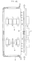
- Fig. 5 shows the cooling system of the drive unit schematically and conceptually including the upper and lower positional relationship.
- This cooling system is formed by a circulation passage L (shown by the wide arrows with hatching in the figure) utilizing oil as the first coolant and a flow passage F (shown by the thin white arrows in the figure) utilizing cooling water as the second coolant. Accordingly, the present invention is applied to the flow passage which uses this cooling water as the coolant.
- the oil as the first coolant is sucked up by the oil pump O/P from the oil sump 90 through the strainer 91, and cools the generator G and the motor M in the sequence as previously described, after which it is once stored in the bottom of the generator G accommodating portion and the bottom of the motor M accommodating portion of the drive unit case 10 so as to maintain a certain oil level that does not come into contact with the lowermost part of the rotors 22 and 32, and then the overflow portion is returned to the oil sump 90, thereby ending one cycle of circulation.
- the cooling water as the second coolant forms a cooling system for cooling the oil as the first coolant utilizing the space between the partition wall 11, which is formed of an aluminum material or the like having good heat conductivity similar to the drive unit case 10 and which forms an attaching portion of the drive unit case 10 and the inverter U of an independent construction, and a heat transfer wall 13 in the oil circulation passage L within the drive unit case 10 as a flow passage F.
- a construction is adopted wherein a wall-shaped isolating means 12 is disposed between the partition wall 11 and the heat transfer wall 13, and the flow passage F for the cooling water cools the inverter U by heat exchange through the partition wall 11 while flowing between the partition wall 11 and the isolating means 12 and cools the oil by heat exchange with the oil through the heat transfer wall 13 while flowing between the isolating means 12 and the heat transfer wall 13.
- Fig. 6 is an exploded perspective view showing the connecting structure of the drive unit case 10 and the power module forming the inverter U in detail
- Fig. 7 shows the same structure from a different viewpoint.
- Fig. 8 and Fig. 9 show the same structure cut in different sections.
- the coolant containers C 1 , C 2 are provided on the upper part of the motor accommodating portion in the drive unit case 10.
- the coolant container is divided into the coolant container C 1 for the motor and the coolant container C 2 for the generator.
- Halfway in the flow passage L 5 see Fig.
- orifices R 4 , R 5 having different apertures which distribute the feed distribution amounts of oil to both coolant containers C 1 , C 2 according to the thermal loads of the motor M and the generator G, and those oil passages are open at inlets 10d, 10e on the sides of the coolant containers.
- Dams 10i, 10j are provided in positions near the outlet sides of both coolant containers. Further, downstream of the dams 10i, 10j of both coolant containers are formed oil outlets 10g, 10h which are open to the bottom faces of those coolant containers and which function as orifices for adjusting the discharge flow by the setting of the aperture.
- the oil outlet 10g is connected to the intra-axial oil passage L 7 at the shaft end of the stator shaft 21 of the motor M, with the intra-case oil passage L 6 formed in the drive unit case utilized as the flow passage.
- the intra-axial oil passage L 7 is communicated with the peripheral groove formed in an end plate 22b supporting both ends of a core 22a of the motor M through the radial directional oil hole, passes through a plurality of intra-rotor oil passages L 8 , of which both ends are communicated with the peripheral groove, and which are formed in the core 22a in the axial direction, and ends at a discharge hole 22c formed in the end plate 22b.
- both ends of one intra-rotor oil passage L 8 are shown leading to with the discharge hole 22c, but in detail, the construction is such that only one end of each intra-rotor oil passage L 8 is alternately led to the discharge hole 22c of the left and right end plates, thereby preventing an imbalance in the oil running in each rotor oil passage L 8 .
- the oil outlet 10h is led above the stator of the generator G through the intra-case oil passage, as shown in Fig. 8.
- the heat transfer wall 13 which blocks the upper openings of the coolant containers C 1 , C 2 is provided with a large number of cooling fins 13a, 13b on its upper face and lower face, and is constructed from an aluminum material or the like having good heat conductivity similar to the drive unit case 10. In this embodiment, it is an independent member from the drive unit 10 for the convenience of machining, and is fixed to the drive unit case 10 with bolts or the like.
- the oil cooling fins 13b on the lower face side of the heat transfer wall 13 change in height so as to follow the shape of the bottom part of the coolant containers C 1 , C 2 as shown in Fig. 8. The arrangement is such that the fins are positioned on the entire area of the coolant container C 1 so as to improve heat transfer.
- the partition wall 11 to which a power module forming the inverter U is fixed forms a cooling portion of the inverter U and is, in the embodiment, constructed so as to house a heat sink for improving the heat exchange efficiency, and as seen in Fig. 7, is provided with two narrow flow passages in parallel passing through the partition wall 11 turning back and forth. And, in order to run cooling water as the second coolant along this flow passage, an isolating means 12 is provided abutted with the lower face of the partition wall 11.
- the isolating means 12 is of an independent construction from the case and the partition wall because a material having a high insulating property is used for the isolating means 12. However, when the same material is used, it is possible to have an integrated construction with either one of the members.
- the first chamber C 3 facing the partition wall 11 side and the second chamber C 4 facing the drive unit case 10 side are separated and defined by the isolating means 12 between the partition wall 11 and the drive unit case 10, and a flow passage is constructed in which both chambers C 3 , C 4 are connected through the communication passage 12b.
- the oil fed to the coolant containers C 1 , C 2 from the respective inlets 10d, 10e is obstructed by the respective dams 10i, 10j and stored for a certain duration of time, after which it flows in contact with the oil cooling fins 13b on the lower face side of the heat transfer wall 13 to affect sufficient heat exchange. Then, the portions which ran over the dams 10i, 10j are adjusted according to the amount of oil necessary for the motor M and the generator G and discharged from the outlets 10g, 10h.
- the cooling water passes through a hole 12a of the isolating means 12 from an inlet 10k open on the upper face of the drive unit case 10 into the heat sink of the partition wall 11, i.e., the first chamber C 4 , and heat exchange is sufficiently conducted through the passage therein.
- the cooling water is led between the heat transfer wall 13 and the isolating means 12 through the communication passage 12b forming a hole provided in the isolating means 12 in this embodiment where it runs across the heat transfer wall 13 while coming into contact with the water cooling fins 13a on the upper face side of the heat transfer wall 13.
- the cooling water is then led outside the drive unit case 10 from a cooling water outlet 10l formed in the surrounding wall around the opening of the coolant container.
- the cooling water discharged from the drive unit case 10 is cooled by the radiator for cooling the engine or the cooler for exclusive use and then re-circulated.
- the cooling water which flows therein acts as two heat insulating layers, and it becomes possible to block the heat on the motor M side which becomes hotter than the inverter U side by absorbing it in two steps with the cooling water halfway in the flow passage so that it is possible to make it difficult for the heat from the motor to be transferred to the inverter U.
- the sequence is such that the cooling water first cools the power module forming the inverter U through the partition wall 11 and then cools the motor M and the generator G through the oil, the cooling water does not conduct heat exchange directly with the motor M and the generator G or simultaneously with the inverter U. Therefore, it is possible to prevent the cooling water temperature from rising above the heat resistant temperature of the inverter U. Accordingly, it is possible to cool the inverter U, motor M, and generator G efficiently and improve cooling performance. Also, as the flow passage of cooling water is formed in the space between the integrated inverter U and the drive unit case 10, a complicated construction such as that of conventional technology in which an exclusive cooling channel is provided around the drive unit case can be avoided, thus leading to an improvement in space efficiency and a reduction in cost.
- the coolant container by separating the coolant container into a coolant container C 1 for the motor and a coolant container C 2 for the generator, it becomes possible to individually adjust the amount of oil to be supplied to the motor M and the generator G, respectively, from the coolant container. Accordingly, by adjusting the flow ratio with the orifices R 4 , R 5 having different apertures and supplying the proper amount of oil to the motor M and the generator G, the respective objects can be effectively cooled according to their cooling temperature requirements.
- the flow of the cooling water as the second coolant is a flow with an upper and lower flow relationship turning back from the first chamber C 3 on the inverter U side to the second chamber C 4 side on the coolant container side, as illustrated most clearly in Fig. 5, such that this flow is a parallel flow.
- Fig. 10 shows this type of second embodiment with a schematic diagram similar to that of Fig. 5.
- the first chamber C 3 facing the partition wall 11 side, which is divided into upper and lower areas by the isolating means 12, and the second chamber C 4 facing the circulating passage L side for the first coolant of the drive unit case 10, i.e., the heat transfer wall 13, are flow passages connected in parallel with the circulating passage for second coolant. Since the rest of construction is substantially same as in the first embodiment described above, all corresponding members are indicated with the same reference numerals and substituted instead of being described (in this respect, all of the subsequent embodiments are the same).
- Fig. 11 shows a third embodiment wherein the relationship of the upper and lower flows in the first chamber C 3 on the inverter U side and the second chamber C 4 on the coolant container side are reversed.
- the cooling water as the second coolant first flows on the second chamber C 4 side which faces the circulation passage L side for the first coolant of the drive unit case 10, i.e., the heat transfer wall 13, to cool the oil through the heat transfer wall 13.
- the isolating means 12 flows in the first chamber C 3 facing the partition wall 11 side which is divided into upper and lower parts by the isolating means 12 to cool the power module of the inverter U.
- the cooling structure becomes such that the cooling water as the second coolant does not directly cool the motor M and the generator G, but cools the oil which circulates and cools them and the inverter U sequentially. Therefore, the heat from the motor M and the generator G is reduced by heat exchange with the cooling water through the oil, as opposed to direct heat transfer, such that an advantage is gained in that it is possible to prevent the temperature of the cooling water from rising above the heat resistant temperature of the inverter U.
- Fig. 12 shows a fourth embodiment wherein the structure of the members forming the flow passage has been modified with respect to one adopting a flow passage structure for the second coolant similar to the first embodiment or the second embodiment.
- a construction is adopted wherein an independent surrounding wall member 14 is interposed between the drive unit case 10 and the partition wall 11, and further, the independent isolating means 12 is interposed between the partition wall 11 and the surrounding wall member 14.
- the surrounding wall member 14 in this case may also be constructed with an aluminum material or the like of the same type as the material for the drive unit case 10 and the partition wall 11, or may be constructed with a material having a high heat insulating property of the same type as that of the isolating means 12.
- the first and second coolant containers C 1 , C 2 are respectively provided on the upper part of the motor M and the generator G.
- Fig. 13 similarly shows a fifth embodiment wherein the structure of the members forming the flow passage has been modified with respect to one adopting a flow passage construction for second coolant similar to the first embodiment or the third embodiment.
- a construction is adopted wherein independent isolating means 12 is interposed between the partition wall 11 and the drive unit case 10.
- the isolating means 12 in this case has a construction such that it is integrally provided therearound with a surrounding wall part 12c which forms a connecting part between the drive unit case 10 and the partition wall 11.
- a cooling system is adopted wherein oil is used as a coolant for directly cooling the motor M and the generator G side, and secondary cooling of the oil is conducted with cooling water as a second coolant for cooling the inverter U
- the present invention can also be embodied by a system for cooling the motor M, the generator G, and the inverter U with a single coolant.
- Fig. 14 and Fig. 15 show a sixth embodiment using this type of cooling system. As illustrated by the flow passage construction shown schematically in Fig. 14, in this embodiment, the downstream side of the flow passage passing through the first and second chambers C 3 , C 4 is communicated with the flow passage in the drive unit case 10 for cooling the motor M and the generator G.
- the partition wall 11 in this embodiment is constructed in a lid shape, covering the drive unit case 10 and containing the first chamber C 3 and the second chamber C 4 , i.e., in a shape having a surrounding wall 11' therearound, and the isolating means 12 for separating the first chamber C 3 and the second chamber C 4 is disposed on the partition wall 11 side.
- the isolating means 12 in this case may be an independent member from the partition wall 11 as illustrated in the figure or may be integrated with the partition wall 11. According to this construction, the first chamber C 3 and the second chamber C 4 are separated by the isolating means 12 which is disposed nearer to the inverter U from the joint face of the partition wall 11 and the drive unit case 10.
- the downstream side of the flow passage passing through the first and the second chambers C 3 , C 4 is communicated with the flow passage in the drive unit case 10 wall, where it first passes through a flow passage F G formed along the outer periphery of the stator 20 of the generator G, then passes through a flow passage F M formed along the outer periphery of the stator 30 of the motor M in the peripheral wall of the drive unit case 10 in the same manner, and is finally led to a position adjacent to the partition wall 11 of the drive unit case 10 where it ends at an outlet opening formed therein.
- the flow passage for the cooling water between the drive unit case 10 and the partition wall 11 can be constructed mainly on the partition wall 11 side, so that the structure of the drive unit case 10 can be simplified and the inverter U, the motor M, and the generator G can be cooled with a simple structure. Also, because the isolating means 12 is on the partition wall 11 side, heat resistance is generated when the heat from the motor M and the generator G is transferred to the isolating means 12, thereby making it possible to make it difficult for the heat from the motor M and the generator G to be transferred to the coolant which flows through the first chamber C 3 on the inverter U side.
- the partition wall 11 extends toward the motor M and the generator G side farther than the isolating means 12, such that the heat capacity of the partition wall 11 can be increased by that amount.
- FIG. 16 shows schematically a seventh embodiment wherein the first chamber C 3 facing the partition wall 11 side and the second chamber C 4 facing the drive unit case 10 side are formed in two layers and communicated in parallel together with the flow passage for coolant.
- a flow passage is formed in the wall of the drive unit case similar to that of the aforementioned sixth embodiment, and this flow passage is communicated with the flow passage for coolant in a parallel relationship with the flow passage passing through the first and the second chambers C 3 , C 4 .
- Fig. 17 shows an eighth embodiment wherein the relationship of the upper and lower flows of the first chamber C 3 on the inverter U side and the second chamber C 4 on the coolant container side is reversed.
- a flow passage is formed in the wall of the drive unit case similar to that of the aforementioned sixth embodiment, and this flow passage is communicated in serial with the upstream side of the flow passage passing through the first and the second chambers C 3 , C 4 .
- the cooling water as a coolant first conducts heat exchange with the motor M and the generator G through the drive unit case 10 wall when it flows through the flow passage in the wall of the case 10 wall.
- the present invention has been described in detail based on eight embodiments. However, the present invention is not limited to these embodiments but can be implemented with various modifications of the specific construction within the scope of the matter described in the claims.
- the second coolant is illustrated as cooling water, but naturally other appropriate coolants may be used.
- the drive unit which uses an electric motor as a driving source and which has an integrated inverter, the electric motor and the inverter are efficiently cooled.
- the drive unit comprises a drive unit case, an electric motor, and an inverter fixed to a drive unit case, and is provided with a coolant flow passage for them between the drive unit case and the inverter.
- the inverter is fixed to the drive unit case through a partition wall, and chambers, forming a two-layered coolant flow passage are formed between the partition wall and the drive unit case.
- the coolant which flows through the coolant flow passage acts as a two-step shielding means against the heat transmitted from the electric motor to the inverter.
Landscapes
- Engineering & Computer Science (AREA)
- Power Engineering (AREA)
- Transportation (AREA)
- Mechanical Engineering (AREA)
- Combustion & Propulsion (AREA)
- Chemical & Material Sciences (AREA)
- Sustainable Development (AREA)
- Sustainable Energy (AREA)
- Life Sciences & Earth Sciences (AREA)
- Microelectronics & Electronic Packaging (AREA)
- Motor Or Generator Cooling System (AREA)
- Hybrid Electric Vehicles (AREA)
- Motor Or Generator Frames (AREA)
- Electric Propulsion And Braking For Vehicles (AREA)
Abstract
Description
Claims (9)
- A drive unit comprising:an electric motor;a drive unit case for accommodating said electric motor;an inverter fixed to the drive unit case for controlling said electric motor; anda flow passage for a coolant for cooling the electric motor, characterized in that said inverter is fixed to the drive unit case through a partition wall; anda first chamber facing the partition wall side and a second chamber facing the drive unit case side are formed in two layers between the pertiton wall and the drive unit case and communicated with the flow passage for coolant.
- The drive unit according to claim 1, wherein the space between said first chamber and second chamber is separated by independent isolating means disposed on the partition wall side.
- The drive unit according to claim 1 or 2, wherein said first chamber and second chamber are communicated together by a communication passage, and are communicated in serial with the flow passage for coolant, with the first chamber side disposed upstream.
- The drive unit according to claim 1 or 2, wherein said first chamber and the second chamber are communicated in parallel together with the flow passage for coolant.
- The drive unit according to claim 1, 3, or 4, wherein said first chamber and the second chamber are separated by the independent isolating means which prevents contact between the partition wall and the drive unit case.
- The drive unit according to claim 2 or 5, wherein said isolating means comprises a material having low heat conductivity.
- The drive unit according to claim 1, wherein said partition wall is constructed in a lid shape which contains the first chamber and the second chamber and covers the drive unit case, and isolating means for separating the first chamber and the second chamber is disposed on the partition wall side.
- The drive unit according to claim 1, wherein said partition wall is constructed in a lid shape which contains the first chamber and covers the drive unit case, and isolating means for separating the first chamber and the second chamber is supported between the drive unit case and the partition wall so as to prevent contact at an abutting portion of the drive unit case and the partition wall side.
- The drive unit according to claim 1, wherein said first chamber and the second chamber are separated by the isolating means disposed nearer to the inverter than the abutting face of the partition wall and the drive unit case.
Applications Claiming Priority (6)
| Application Number | Priority Date | Filing Date | Title |
|---|---|---|---|
| JP12028699 | 1999-04-27 | ||
| JP12028699 | 1999-04-27 | ||
| JP35673499 | 1999-12-15 | ||
| JP35673499 | 1999-12-15 | ||
| JP2000088590A JP3886696B2 (en) | 1999-04-27 | 2000-03-24 | Drive device |
| JP2000088590 | 2000-03-24 |
Publications (3)
| Publication Number | Publication Date |
|---|---|
| EP1049235A2 true EP1049235A2 (en) | 2000-11-02 |
| EP1049235A3 EP1049235A3 (en) | 2003-10-22 |
| EP1049235B1 EP1049235B1 (en) | 2007-01-03 |
Family
ID=27314019
Family Applications (1)
| Application Number | Title | Priority Date | Filing Date |
|---|---|---|---|
| EP00108839A Expired - Lifetime EP1049235B1 (en) | 1999-04-27 | 2000-04-26 | Drive unit |
Country Status (4)
| Country | Link |
|---|---|
| US (1) | US6201365B1 (en) |
| EP (1) | EP1049235B1 (en) |
| JP (1) | JP3886696B2 (en) |
| DE (1) | DE60032665T2 (en) |
Cited By (27)
| Publication number | Priority date | Publication date | Assignee | Title |
|---|---|---|---|---|
| EP1217261A3 (en) * | 2000-12-20 | 2005-03-30 | Sew-Eurodrive GmbH & Co. KG | Optimization of the time intervals for oil-change for a transmission |
| EP1093958A3 (en) * | 1999-10-18 | 2005-06-08 | Aisin Aw Co., Ltd. | Vehicle drive unit |
| EP1571751A1 (en) * | 2004-03-03 | 2005-09-07 | Hitachi, Ltd. | Vehicle drive device and four-wheel drive with motor |
| WO2008011958A1 (en) * | 2006-07-22 | 2008-01-31 | Daimler Ag | Motor vehicle |
| FR2912695A1 (en) * | 2007-02-21 | 2008-08-22 | Renault Sas | Power distribution transmission for motor vehicle, has coolant circuit of electric machine formed at part in transmission housing, another coolant circuit of another electric machine formed in housing, and unit for connecting circuits |
| WO2010049244A1 (en) * | 2008-10-31 | 2010-05-06 | Robert Bosch Gmbh | Hybrid drive unit |
| EP2225119A1 (en) * | 2007-12-20 | 2010-09-08 | Volvo Lastvagnar AB | Arrangement for a power electronics unit in a hybrid vehicle |
| CN101850713A (en) * | 2010-03-31 | 2010-10-06 | 重庆长安汽车股份有限公司 | Water-cooled motor controller of hybrid electric vehicle |
| EP2247460A1 (en) * | 2008-02-26 | 2010-11-10 | Volvo Lastvagnar AB | Arrangement for a power electronics unit in a hybrid vehicle |
| WO2011110253A1 (en) * | 2010-03-11 | 2011-09-15 | Zf Friedrichshafen Ag | Hybrid transmission |
| US8074753B2 (en) | 2005-10-26 | 2011-12-13 | Toyota Jidosha Kabushiki Kaisha | Drive device of vehicle |
| DE10142751B4 (en) * | 2000-12-20 | 2012-04-12 | Sew-Eurodrive Gmbh & Co. Kg | Device for a drive and method for the device |
| WO2012107826A1 (en) * | 2011-02-10 | 2012-08-16 | Toyota Jidosha Kabushiki Kaisha | Power control unit |
| WO2013110677A3 (en) * | 2012-01-24 | 2014-01-23 | Avl List Gmbh | Electric drive unit |
| WO2015078465A1 (en) * | 2013-11-26 | 2015-06-04 | Schaeffler Technologies AG & Co. KG | Hybrid module and power electronics module with a common coolant flow |
| EP2905881A4 (en) * | 2012-10-03 | 2016-06-01 | Schaft Inc | Water-cooled motor structure and water-cooled housing |
| WO2016087101A1 (en) * | 2014-12-01 | 2016-06-09 | Volkswagen Aktiengesellschaft | Electric drive unit, hybrid drive device, and vehicle |
| CN106458005A (en) * | 2014-06-13 | 2017-02-22 | 舍弗勒技术股份两合公司 | Hybrid module designed as an insertable module |
| WO2017071892A1 (en) * | 2015-10-27 | 2017-05-04 | Zf Friedrichshafen Ag | Assembly unit for an electrical drive unit inside a drive train of a vehicle |
| WO2017071893A1 (en) * | 2015-10-27 | 2017-05-04 | Zf Friedrichshafen Ag | Electric drive unit for a drive train of a vehicle |
| EP3220517A1 (en) * | 2016-03-15 | 2017-09-20 | Honda Motor Co., Ltd. | Electric power unit |
| EP3597461A1 (en) * | 2018-07-19 | 2020-01-22 | FLET GmbH | Electric vehicle |
| EP3672036A1 (en) * | 2018-12-17 | 2020-06-24 | BorgWarner Inc. | Liquid-cooled enclosure for turbocharger power module |
| FR3091838A1 (en) * | 2019-01-22 | 2020-07-24 | Valeo Embrayages | Propulsion module of an electric or hybrid vehicle |
| WO2020216501A1 (en) * | 2019-04-23 | 2020-10-29 | Zf Friedrichshafen Ag | Transmission arrangement for a motor vehicle and motor vehicle |
| WO2020228881A1 (en) * | 2019-05-16 | 2020-11-19 | Schaeffler Technologies AG & Co. KG | Drive device having a heat exchanger arranged underneath a power electronics unit |
| WO2021047718A1 (en) * | 2019-09-10 | 2021-03-18 | Schaeffler Technologies AG & Co. KG | Coolable electric drive device, and drive arrangement |
Families Citing this family (78)
| Publication number | Priority date | Publication date | Assignee | Title |
|---|---|---|---|---|
| JP4048311B2 (en) * | 2000-03-17 | 2008-02-20 | 株式会社豊田自動織機 | Electric compressor |
| DE60135761D1 (en) * | 2000-09-22 | 2008-10-23 | Aisin Aw Co | SUPPLY FOR ELECTRONIC CIRCUITS |
| US20030218057A1 (en) * | 2000-11-07 | 2003-11-27 | Craig Joseph | Electrical bus with associated porous metal heat sink and method of manufacturing same |
| JP3882994B2 (en) * | 2001-12-27 | 2007-02-21 | アイシン・エィ・ダブリュ株式会社 | Motor control unit cooling device |
| US6914354B2 (en) * | 2002-01-16 | 2005-07-05 | Ballard Power Systems Corporation | Assembly and method for direct cooling of motor end-winding |
| US7102260B2 (en) | 2002-09-13 | 2006-09-05 | Aisin Aw Co., Ltd. | Drive device |
| US7030520B2 (en) | 2002-09-13 | 2006-04-18 | Aisin Aw Co., Ltd. | Drive device |
| JP4096265B2 (en) | 2002-09-13 | 2008-06-04 | アイシン・エィ・ダブリュ株式会社 | Drive device |
| DE10248715A1 (en) * | 2002-10-18 | 2004-05-13 | Compact Dynamics Gmbh | Hybrid drive for a motor vehicle |
| JP3794392B2 (en) * | 2003-02-25 | 2006-07-05 | 日産自動車株式会社 | Electric vehicle drive unit |
| JP4186109B2 (en) * | 2003-06-25 | 2008-11-26 | アイシン・エィ・ダブリュ株式会社 | Drive device |
| JP2007166804A (en) * | 2005-12-14 | 2007-06-28 | Toyota Motor Corp | Motor drive and vehicle having the same |
| JP2007189865A (en) * | 2006-01-16 | 2007-07-26 | Mitsubishi Electric Corp | Rotary electric machine integrated with control unit |
| JP4675311B2 (en) * | 2006-11-16 | 2011-04-20 | トヨタ自動車株式会社 | Inverter and condenser cooling structure accommodated integrally with motor in motor housing, motor unit and housing having the cooling structure |
| JP4579256B2 (en) | 2007-01-04 | 2010-11-10 | トヨタ自動車株式会社 | Vehicle drive device mounting structure |
| JP4633761B2 (en) | 2007-05-25 | 2011-02-16 | トヨタ自動車株式会社 | Drive mechanism |
| JP4678385B2 (en) * | 2007-06-13 | 2011-04-27 | トヨタ自動車株式会社 | DRIVE DEVICE AND VEHICLE HAVING DRIVE DEVICE |
| JP4465667B2 (en) * | 2007-08-01 | 2010-05-19 | いすゞ自動車株式会社 | Hybrid electric vehicle battery box structure |
| JP2009247119A (en) * | 2008-03-31 | 2009-10-22 | Aisin Aw Co Ltd | Drive device |
| IT1393872B1 (en) * | 2009-04-22 | 2012-05-11 | Ansaldo Ricerche S P A | COOLING SYSTEM FOR HIGH VOLTAGE POWER DENSITY ELECTRIC MOTOR, IN PARTICULAR ELECTRIC AXIAL FLOW MOTOR |
| US8169110B2 (en) * | 2009-10-09 | 2012-05-01 | GM Global Technology Operations LLC | Oil cooled motor/generator for an automotive powertrain |
| JP5498773B2 (en) * | 2009-12-24 | 2014-05-21 | 株式会社日本自動車部品総合研究所 | Rotating electric machine |
| DE102010007636B4 (en) | 2010-02-05 | 2023-12-14 | Dr. Ing. H.C. F. Porsche Aktiengesellschaft | Electric machine arrangement |
| DE102010002068A1 (en) * | 2010-02-18 | 2011-08-18 | Siemens Aktiengesellschaft, 80333 | motor unit |
| AU2011271498B2 (en) * | 2010-07-01 | 2015-11-05 | Allison Transmission, Inc. | Modes of cooling hybrid electric machines |
| US20120112568A1 (en) * | 2010-11-04 | 2012-05-10 | Remy Technologies, L.L.C. | Cooling system for an electric machine system including an alternating current (ac) electric machine having an integrated switch assembly |
| JP5338787B2 (en) * | 2010-11-05 | 2013-11-13 | 三菱自動車工業株式会社 | Cooling system |
| DE102011015623A1 (en) * | 2011-03-31 | 2012-10-04 | Magna Powertrain Ag & Co. Kg | Electric drive unit |
| NO334268B1 (en) * | 2011-04-15 | 2014-01-27 | Apply Nemo As | An underwater cooling device |
| JP5794198B2 (en) * | 2012-05-11 | 2015-10-14 | トヨタ自動車株式会社 | Cooling control device |
| KR101375956B1 (en) * | 2012-07-05 | 2014-03-18 | 엘에스산전 주식회사 | Electronic component box for vehicle |
| US9370994B2 (en) * | 2012-08-24 | 2016-06-21 | Nissan Motor Co., Ltd. | Integrated power electric unit mounted on electric vehicle |
| US9048708B2 (en) * | 2012-11-05 | 2015-06-02 | Rockwell Automation Technologies, Inc. | Integrated drive-motor assembly with IP seal and enhanced heat transfer |
| US9216882B2 (en) * | 2013-01-08 | 2015-12-22 | Komatsu Ltd. | Battery powered work machine, and battery powered forklift |
| US9452682B2 (en) * | 2013-01-18 | 2016-09-27 | GM Global Technology Operations LLC | Transmission for a vehicle |
| US8813896B2 (en) * | 2013-01-18 | 2014-08-26 | GM Global Technology Operations LLC | Vehicle |
| US20140202279A1 (en) * | 2013-01-18 | 2014-07-24 | GM Global Technology Operations LLC | Transmission for a vehicle |
| JP2015008595A (en) * | 2013-06-25 | 2015-01-15 | 日産自動車株式会社 | Machinery and electricity integrated drive apparatus for electrically-driven vehicle |
| WO2015054588A2 (en) * | 2013-10-11 | 2015-04-16 | Eaton Corporation | Electric motor driven pump |
| JP5907151B2 (en) * | 2013-11-29 | 2016-04-20 | トヨタ自動車株式会社 | Car electronics case |
| DE102014103471A1 (en) * | 2014-03-14 | 2015-09-17 | Dr. Ing. H.C. F. Porsche Aktiengesellschaft | Electric actuator |
| US9415673B2 (en) * | 2014-06-30 | 2016-08-16 | Faster Faster Inc. | Integrated chassis heatsink for electric vehicles |
| JP6402646B2 (en) * | 2015-02-19 | 2018-10-10 | 株式会社豊田自動織機 | Electric supercharger |
| US10442285B2 (en) * | 2015-11-24 | 2019-10-15 | Toyota Jidosha Kabushiki Kaisha | Cooling apparatus for vehicle |
| JP6638410B2 (en) * | 2016-01-13 | 2020-01-29 | 富士電機株式会社 | Power converter integrated motor |
| JP6638427B2 (en) * | 2016-01-29 | 2020-01-29 | 富士電機株式会社 | Outer rotor type rotary electric machine |
| JPWO2018030371A1 (en) | 2016-08-09 | 2019-06-13 | 日本電産株式会社 | Motor unit |
| US11616419B2 (en) * | 2016-08-09 | 2023-03-28 | Nidec Corporation | Motor unit with oil cooling passage |
| US10910918B2 (en) | 2016-08-09 | 2021-02-02 | Nidec Corporation | Motor |
| WO2018030348A1 (en) | 2016-08-09 | 2018-02-15 | 日本電産株式会社 | Motor unit |
| CN109565225B (en) | 2016-08-09 | 2021-02-12 | 日本电产株式会社 | Motor unit |
| CN109563920B (en) | 2016-08-09 | 2022-09-09 | 日本电产株式会社 | Motor unit |
| JP7088013B2 (en) | 2016-08-09 | 2022-06-21 | 日本電産株式会社 | Motor unit |
| US10903705B2 (en) | 2016-08-09 | 2021-01-26 | Nidec Corporation | Motor |
| DE112017004030T5 (en) | 2016-08-09 | 2019-05-09 | Nidec Corporation | ENGINE |
| US10862365B2 (en) | 2016-08-09 | 2020-12-08 | Nidec Corporation | Motor unit |
| EP3507121A1 (en) | 2016-08-31 | 2019-07-10 | BorgWarner Sweden AB | A hybrid drive module having an electric motor |
| CN107070104B (en) * | 2016-11-25 | 2023-08-22 | 重庆谱思机器人控制系统有限公司 | Connection method of closed-loop integrated stepping motor |
| JP6680263B2 (en) | 2017-05-19 | 2020-04-15 | トヨタ自動車株式会社 | Hybrid vehicle drive |
| JP6604997B2 (en) * | 2017-07-06 | 2019-11-13 | 本田技研工業株式会社 | Cooling system |
| KR102435827B1 (en) * | 2017-09-18 | 2022-08-25 | 로베르트 보쉬 게엠베하 | electric drive system |
| JP6628779B2 (en) | 2017-10-25 | 2020-01-15 | 本田技研工業株式会社 | Mechanical and electrical integrated rotary electric machine |
| US10396631B2 (en) * | 2017-10-31 | 2019-08-27 | Nio Usa, Inc. | Dual inverter and electric motor split-flow cooling system |
| CN112770926A (en) * | 2018-09-25 | 2021-05-07 | 日本电产株式会社 | Drive device |
| CN109510402A (en) * | 2019-01-18 | 2019-03-22 | 中国第汽车股份有限公司 | A kind of used in new energy vehicles oil-cooled motor system |
| US11996756B2 (en) | 2019-03-06 | 2024-05-28 | Nidec Corporation | Motor unit |
| DE102019109313B4 (en) | 2019-04-09 | 2021-09-30 | Schaeffler Technologies AG & Co. KG | Electric drive with heat exchanger section |
| DE112020001868T5 (en) * | 2019-04-11 | 2021-12-30 | Nidec Corporation | MOTOR UNIT |
| FR3096525B1 (en) * | 2019-05-20 | 2021-07-02 | Valeo Embrayages | Propulsion module of an electric or hybrid vehicle |
| DE102019215036A1 (en) * | 2019-09-30 | 2021-04-01 | Mahle International Gmbh | System with a gear mechanism and a circuit board |
| CN114556752A (en) * | 2019-11-02 | 2022-05-27 | 博格华纳公司 | Drive module with improved efficiency |
| DE102019132164A1 (en) * | 2019-11-27 | 2021-05-27 | Schaeffler Technologies AG & Co. KG | Electric motor assembly |
| JP2022108687A (en) | 2021-01-13 | 2022-07-26 | 本田技研工業株式会社 | Vehicle drive device |
| JP2022108688A (en) | 2021-01-13 | 2022-07-26 | 本田技研工業株式会社 | Vehicle temperature control system |
| JP2022108685A (en) | 2021-01-13 | 2022-07-26 | 本田技研工業株式会社 | vehicle |
| US11993166B2 (en) * | 2021-04-29 | 2024-05-28 | Rivian Ip Holdings, Llc | Inverter module integratably mountable with drive unit of vehicle |
| DE102022109719A1 (en) | 2022-04-22 | 2023-10-26 | Schaeffler Technologies AG & Co. KG | Heat exchanger arrangement with a heat sink having a sheet metal plate with an integrated cooling channel; and electric drive system |
| DE102022109797A1 (en) | 2022-04-22 | 2023-10-26 | Dr. Ing. H.C. F. Porsche Aktiengesellschaft | Drive system for an at least partially electrically driven motor vehicle |
Citations (1)
| Publication number | Priority date | Publication date | Assignee | Title |
|---|---|---|---|---|
| JPH07288949A (en) | 1994-04-13 | 1995-10-31 | Nippondenso Co Ltd | Electric motor to drive vehicle |
Family Cites Families (13)
| Publication number | Priority date | Publication date | Assignee | Title |
|---|---|---|---|---|
| US4711204A (en) * | 1983-08-08 | 1987-12-08 | Rusconi David M | Apparatus and method for cold weather protection of large diesel engines |
| JPS60141147A (en) * | 1983-12-28 | 1985-07-26 | Toshiba Corp | Controller-containing rotary electric machine |
| JPH02106249A (en) * | 1988-10-13 | 1990-04-18 | Fanuc Ltd | Device for cooling spindle driving control device |
| ATA105093A (en) * | 1993-05-28 | 2001-07-15 | Steyr Daimler Puch Ag | LIQUID-COOLED DRIVE UNIT FOR AN ELECTROMOBILE |
| JP3345127B2 (en) | 1993-09-24 | 2002-11-18 | マツダ株式会社 | Electric vehicle motor unit structure |
| JPH07194139A (en) * | 1993-12-27 | 1995-07-28 | Hitachi Ltd | Cooling device of inverter for electric automobile |
| GB2289581A (en) * | 1994-05-14 | 1995-11-22 | Marconi Gec Ltd | Alternator and static converter system |
| US5670860A (en) * | 1995-06-06 | 1997-09-23 | Hughes Electronics | High power, high frequency, liquid-cooled transmission cable and charging system |
| JP3327317B2 (en) * | 1995-10-09 | 2002-09-24 | 株式会社荏原製作所 | Inverter water cooling |
| JPH09275664A (en) * | 1996-04-02 | 1997-10-21 | Toyota Autom Loom Works Ltd | Motor controlling system |
| US5905647A (en) * | 1997-01-20 | 1999-05-18 | Kabushiki Kaisha Toshiba | Inverter with incorporated filter circuit and improved component cooling arrangement |
| JPH10271763A (en) * | 1997-03-25 | 1998-10-09 | Toshiba Corp | Motor fitted with controller and permanent magnet motor |
| DE19817333C5 (en) * | 1998-04-18 | 2007-04-26 | Conti Temic Microelectronic Gmbh | Electric drive unit consisting of electric motor and electronic module |
-
2000
- 2000-03-24 JP JP2000088590A patent/JP3886696B2/en not_active Expired - Lifetime
- 2000-04-26 US US09/558,163 patent/US6201365B1/en not_active Expired - Lifetime
- 2000-04-26 EP EP00108839A patent/EP1049235B1/en not_active Expired - Lifetime
- 2000-04-26 DE DE60032665T patent/DE60032665T2/en not_active Expired - Lifetime
Patent Citations (1)
| Publication number | Priority date | Publication date | Assignee | Title |
|---|---|---|---|---|
| JPH07288949A (en) | 1994-04-13 | 1995-10-31 | Nippondenso Co Ltd | Electric motor to drive vehicle |
Cited By (42)
| Publication number | Priority date | Publication date | Assignee | Title |
|---|---|---|---|---|
| EP1093958A3 (en) * | 1999-10-18 | 2005-06-08 | Aisin Aw Co., Ltd. | Vehicle drive unit |
| EP1217261A3 (en) * | 2000-12-20 | 2005-03-30 | Sew-Eurodrive GmbH & Co. KG | Optimization of the time intervals for oil-change for a transmission |
| DE10142751B4 (en) * | 2000-12-20 | 2012-04-12 | Sew-Eurodrive Gmbh & Co. Kg | Device for a drive and method for the device |
| EP1571751A1 (en) * | 2004-03-03 | 2005-09-07 | Hitachi, Ltd. | Vehicle drive device and four-wheel drive with motor |
| US8074753B2 (en) | 2005-10-26 | 2011-12-13 | Toyota Jidosha Kabushiki Kaisha | Drive device of vehicle |
| WO2008011958A1 (en) * | 2006-07-22 | 2008-01-31 | Daimler Ag | Motor vehicle |
| US8857543B2 (en) | 2006-07-22 | 2014-10-14 | Daimler A.G. | Motor vehicle |
| FR2912695A1 (en) * | 2007-02-21 | 2008-08-22 | Renault Sas | Power distribution transmission for motor vehicle, has coolant circuit of electric machine formed at part in transmission housing, another coolant circuit of another electric machine formed in housing, and unit for connecting circuits |
| EP2225119A1 (en) * | 2007-12-20 | 2010-09-08 | Volvo Lastvagnar AB | Arrangement for a power electronics unit in a hybrid vehicle |
| EP2225119A4 (en) * | 2007-12-20 | 2013-02-27 | Volvo Lastvagnar Ab | Arrangement for a power electronics unit in a hybrid vehicle |
| EP2247460A1 (en) * | 2008-02-26 | 2010-11-10 | Volvo Lastvagnar AB | Arrangement for a power electronics unit in a hybrid vehicle |
| EP2247460A4 (en) * | 2008-02-26 | 2013-02-27 | Volvo Lastvagnar Ab | Arrangement for a power electronics unit in a hybrid vehicle |
| WO2010049244A1 (en) * | 2008-10-31 | 2010-05-06 | Robert Bosch Gmbh | Hybrid drive unit |
| WO2011110253A1 (en) * | 2010-03-11 | 2011-09-15 | Zf Friedrichshafen Ag | Hybrid transmission |
| CN101850713A (en) * | 2010-03-31 | 2010-10-06 | 重庆长安汽车股份有限公司 | Water-cooled motor controller of hybrid electric vehicle |
| WO2012107826A1 (en) * | 2011-02-10 | 2012-08-16 | Toyota Jidosha Kabushiki Kaisha | Power control unit |
| WO2013110677A3 (en) * | 2012-01-24 | 2014-01-23 | Avl List Gmbh | Electric drive unit |
| US9768662B2 (en) | 2012-10-03 | 2017-09-19 | Schaft Inc. | Water-cooled motor structure and water-cooled housing |
| EP2905881A4 (en) * | 2012-10-03 | 2016-06-01 | Schaft Inc | Water-cooled motor structure and water-cooled housing |
| CN105745103A (en) * | 2013-11-26 | 2016-07-06 | 舍弗勒技术股份两合公司 | Hybrid module and power electronics module with a common coolant flow |
| US10348161B2 (en) | 2013-11-26 | 2019-07-09 | Schaeffler Technologies AG & Co. KG | Hybrid module and power electronics module with a shared cooling stream |
| EP3074254B1 (en) | 2013-11-26 | 2019-04-10 | Schaeffler Technologies AG & Co. KG | Hybrid module and power electronics module with a common coolant flow |
| WO2015078465A1 (en) * | 2013-11-26 | 2015-06-04 | Schaeffler Technologies AG & Co. KG | Hybrid module and power electronics module with a common coolant flow |
| CN106458005B (en) * | 2014-06-13 | 2019-08-06 | 舍弗勒技术股份两合公司 | It is configured for insertion into the hybrid power module of formula module |
| US10093164B2 (en) | 2014-06-13 | 2018-10-09 | Schaeffler Technologies AG & Co. KG | Hybrid module designed as an insertable module |
| CN106458005A (en) * | 2014-06-13 | 2017-02-22 | 舍弗勒技术股份两合公司 | Hybrid module designed as an insertable module |
| CN107005127A (en) * | 2014-12-01 | 2017-08-01 | 大众汽车有限公司 | Electrical driving unit, hybrid driving apparatus and the vehicles |
| US10500937B2 (en) | 2014-12-01 | 2019-12-10 | Volkswagen Aktiengesellschaft | Electric drive unit, hybrid drive device, and vehicle |
| WO2016087101A1 (en) * | 2014-12-01 | 2016-06-09 | Volkswagen Aktiengesellschaft | Electric drive unit, hybrid drive device, and vehicle |
| WO2017071892A1 (en) * | 2015-10-27 | 2017-05-04 | Zf Friedrichshafen Ag | Assembly unit for an electrical drive unit inside a drive train of a vehicle |
| WO2017071893A1 (en) * | 2015-10-27 | 2017-05-04 | Zf Friedrichshafen Ag | Electric drive unit for a drive train of a vehicle |
| CN107204675A (en) * | 2016-03-15 | 2017-09-26 | 本田技研工业株式会社 | Electric power unit |
| EP3220517A1 (en) * | 2016-03-15 | 2017-09-20 | Honda Motor Co., Ltd. | Electric power unit |
| EP3597461A1 (en) * | 2018-07-19 | 2020-01-22 | FLET GmbH | Electric vehicle |
| EP3672036A1 (en) * | 2018-12-17 | 2020-06-24 | BorgWarner Inc. | Liquid-cooled enclosure for turbocharger power module |
| US11125108B2 (en) | 2018-12-17 | 2021-09-21 | Borgwarner Inc. | Liquid-cooled enclosure for turbocharger power module |
| FR3091838A1 (en) * | 2019-01-22 | 2020-07-24 | Valeo Embrayages | Propulsion module of an electric or hybrid vehicle |
| WO2020151996A1 (en) * | 2019-01-22 | 2020-07-30 | Valeo Embrayages | Propulsion module for an electric or hybrid vehicle |
| CN114604106A (en) * | 2019-01-22 | 2022-06-10 | 法雷奥离合器公司 | Propulsion module for an electric or hybrid vehicle |
| WO2020216501A1 (en) * | 2019-04-23 | 2020-10-29 | Zf Friedrichshafen Ag | Transmission arrangement for a motor vehicle and motor vehicle |
| WO2020228881A1 (en) * | 2019-05-16 | 2020-11-19 | Schaeffler Technologies AG & Co. KG | Drive device having a heat exchanger arranged underneath a power electronics unit |
| WO2021047718A1 (en) * | 2019-09-10 | 2021-03-18 | Schaeffler Technologies AG & Co. KG | Coolable electric drive device, and drive arrangement |
Also Published As
| Publication number | Publication date |
|---|---|
| EP1049235B1 (en) | 2007-01-03 |
| JP3886696B2 (en) | 2007-02-28 |
| EP1049235A3 (en) | 2003-10-22 |
| DE60032665T2 (en) | 2007-10-04 |
| DE60032665D1 (en) | 2007-02-15 |
| US6201365B1 (en) | 2001-03-13 |
| JP2001238405A (en) | 2001-08-31 |
Similar Documents
| Publication | Publication Date | Title |
|---|---|---|
| EP1049235B1 (en) | Drive unit | |
| EP1049234B1 (en) | Drive unit | |
| US10539071B2 (en) | Vehicle drive device | |
| CN106828078B (en) | Cooling device for vehicle | |
| JP3891348B2 (en) | Electric drive | |
| US10938278B2 (en) | Vehicle | |
| US9447864B2 (en) | Vehicle drive device | |
| JP3559891B2 (en) | Cooling structure of multilayer motor | |
| US8074753B2 (en) | Drive device of vehicle | |
| US20200149624A1 (en) | Cooling system for power transmission unit | |
| CN114556752A (en) | Drive module with improved efficiency | |
| JP2011126320A (en) | Clutch and motor housing structure of hybrid electric vehicle | |
| WO2024087601A1 (en) | Hybrid electric drive system and hybrid vehicle | |
| JP2023505664A (en) | Drives and Drive Assemblies | |
| CN115021437A (en) | Stator module, motor and have its car | |
| KR100642994B1 (en) | Drive unit | |
| KR100698923B1 (en) | Drive unit | |
| US11364786B2 (en) | Hybrid electric vehicle with a combined torque converter and an electric propulsion motor | |
| CN217486246U (en) | Stator module, motor and have its car | |
| JP2004072947A (en) | Stator cooling structure of multiple shaft multilayer motor |
Legal Events
| Date | Code | Title | Description |
|---|---|---|---|
| PUAI | Public reference made under article 153(3) epc to a published international application that has entered the european phase |
Free format text: ORIGINAL CODE: 0009012 |
|
| AK | Designated contracting states |
Kind code of ref document: A2 Designated state(s): AT BE CH CY DE DK ES FI FR GB GR IE IT LI LU MC NL PT SE |
|
| AX | Request for extension of the european patent |
Free format text: AL;LT;LV;MK;RO;SI |
|
| PUAL | Search report despatched |
Free format text: ORIGINAL CODE: 0009013 |
|
| AK | Designated contracting states |
Kind code of ref document: A3 Designated state(s): AT BE CH CY DE DK ES FI FR GB GR IE IT LI LU MC NL PT SE |
|
| AX | Request for extension of the european patent |
Extension state: AL LT LV MK RO SI |
|
| 17P | Request for examination filed |
Effective date: 20040402 |
|
| AKX | Designation fees paid |
Designated state(s): DE FR GB |
|
| 17Q | First examination report despatched |
Effective date: 20040727 |
|
| GRAP | Despatch of communication of intention to grant a patent |
Free format text: ORIGINAL CODE: EPIDOSNIGR1 |
|
| GRAS | Grant fee paid |
Free format text: ORIGINAL CODE: EPIDOSNIGR3 |
|
| GRAA | (expected) grant |
Free format text: ORIGINAL CODE: 0009210 |
|
| AK | Designated contracting states |
Kind code of ref document: B1 Designated state(s): DE FR GB |
|
| REG | Reference to a national code |
Ref country code: GB Ref legal event code: FG4D |
|
| REF | Corresponds to: |
Ref document number: 60032665 Country of ref document: DE Date of ref document: 20070215 Kind code of ref document: P |
|
| ET | Fr: translation filed | ||
| PLBE | No opposition filed within time limit |
Free format text: ORIGINAL CODE: 0009261 |
|
| STAA | Information on the status of an ep patent application or granted ep patent |
Free format text: STATUS: NO OPPOSITION FILED WITHIN TIME LIMIT |
|
| 26N | No opposition filed |
Effective date: 20071005 |
|
| REG | Reference to a national code |
Ref country code: FR Ref legal event code: PLFP Year of fee payment: 17 |
|
| REG | Reference to a national code |
Ref country code: FR Ref legal event code: PLFP Year of fee payment: 18 |
|
| REG | Reference to a national code |
Ref country code: FR Ref legal event code: PLFP Year of fee payment: 19 |
|
| PGFP | Annual fee paid to national office [announced via postgrant information from national office to epo] |
Ref country code: FR Payment date: 20190313 Year of fee payment: 20 |
|
| PGFP | Annual fee paid to national office [announced via postgrant information from national office to epo] |
Ref country code: DE Payment date: 20190416 Year of fee payment: 20 |
|
| PGFP | Annual fee paid to national office [announced via postgrant information from national office to epo] |
Ref country code: GB Payment date: 20190424 Year of fee payment: 20 |
|
| REG | Reference to a national code |
Ref country code: DE Ref legal event code: R071 Ref document number: 60032665 Country of ref document: DE |
|
| REG | Reference to a national code |
Ref country code: GB Ref legal event code: PE20 Expiry date: 20200425 |
|
| PG25 | Lapsed in a contracting state [announced via postgrant information from national office to epo] |
Ref country code: GB Free format text: LAPSE BECAUSE OF EXPIRATION OF PROTECTION Effective date: 20200425 |