EP1049231B1 - Parameter measuring method, charge/discharge control method and apparatus and life predicting method for secondary batteries and power storage apparatus using the same - Google Patents
Parameter measuring method, charge/discharge control method and apparatus and life predicting method for secondary batteries and power storage apparatus using the same Download PDFInfo
- Publication number
- EP1049231B1 EP1049231B1 EP00113479A EP00113479A EP1049231B1 EP 1049231 B1 EP1049231 B1 EP 1049231B1 EP 00113479 A EP00113479 A EP 00113479A EP 00113479 A EP00113479 A EP 00113479A EP 1049231 B1 EP1049231 B1 EP 1049231B1
- Authority
- EP
- European Patent Office
- Prior art keywords
- charge
- discharge
- secondary battery
- open
- current
- Prior art date
- Legal status (The legal status is an assumption and is not a legal conclusion. Google has not performed a legal analysis and makes no representation as to the accuracy of the status listed.)
- Expired - Lifetime
Links
Images


Classifications
-
- G—PHYSICS
- G01—MEASURING; TESTING
- G01R—MEASURING ELECTRIC VARIABLES; MEASURING MAGNETIC VARIABLES
- G01R31/00—Arrangements for testing electric properties; Arrangements for locating electric faults; Arrangements for electrical testing characterised by what is being tested not provided for elsewhere
- G01R31/36—Arrangements for testing, measuring or monitoring the electrical condition of accumulators or electric batteries, e.g. capacity or state of charge [SoC]
- G01R31/382—Arrangements for monitoring battery or accumulator variables, e.g. SoC
- G01R31/3828—Arrangements for monitoring battery or accumulator variables, e.g. SoC using current integration
-
- G—PHYSICS
- G01—MEASURING; TESTING
- G01R—MEASURING ELECTRIC VARIABLES; MEASURING MAGNETIC VARIABLES
- G01R31/00—Arrangements for testing electric properties; Arrangements for locating electric faults; Arrangements for electrical testing characterised by what is being tested not provided for elsewhere
- G01R31/36—Arrangements for testing, measuring or monitoring the electrical condition of accumulators or electric batteries, e.g. capacity or state of charge [SoC]
- G01R31/389—Measuring internal impedance, internal conductance or related variables
-
- H—ELECTRICITY
- H02—GENERATION; CONVERSION OR DISTRIBUTION OF ELECTRIC POWER
- H02J—CIRCUIT ARRANGEMENTS OR SYSTEMS FOR SUPPLYING OR DISTRIBUTING ELECTRIC POWER; SYSTEMS FOR STORING ELECTRIC ENERGY
- H02J7/00—Circuit arrangements for charging or depolarising batteries or for supplying loads from batteries
- H02J7/007—Regulation of charging or discharging current or voltage
- H02J7/00712—Regulation of charging or discharging current or voltage the cycle being controlled or terminated in response to electric parameters
- H02J7/00714—Regulation of charging or discharging current or voltage the cycle being controlled or terminated in response to electric parameters in response to battery charging or discharging current
Definitions
- the present invention generally relates to a method of measuring parameters of secondary batteries, a method of controlling charge/discharge of secondary batteries by using the parameters as measured, a method of predicting the life of secondary batteries on the basis of the measured parameters, an apparatus for controlling the charge/discharge process of the secondary batteries and an electric power storage apparatus implemented by using the same. More specifically, the present invention is concerned with a secondary battery parameter measuring method capable of measuring easily and accurately parameters of secondary batteries, a method for controlling the secondary battery so that the life thereof can effectively be extended and a method for predicting the life of a secondary battery, by using the measured parameters. Further, the present invention is directed to a charge/discharge control apparatus for carrying out the charge/discharge control method and an electric energy storing apparatus implemented by utilizing the charge/discharge control apparatus.
- the secondary batteries have been developed for the universal purpose of storing (charging) of electric energy and supplying (discharging) thereof even through they may differ from one to another in respect to the size or capacity and application for which they are designed.
- the polarization resistance R of the secondary battery can be represented as a function of parameters such as environmental or ambient temperature at which the secondary battery are operated and charge/discharge history such as charge/discharge cycle repetition number NC (i.e., the number of times' the secondary battery has been repetitively charged and discharged in the past), not to say of the types and structures of the batteries.
- charge/discharge cycle repetition number NC i.e., the number of times' the secondary battery has been repetitively charged and discharged in the past
- the polarization resistance R may be considered to be substantially constant independent of the temperature except for the case where the secondary battery is exposed to an environment of in which the temperature changes unusually remarkably.
- Figure 12 is a characteristic diagram for graphically illustrating characteristics of the polarization resistance R actually measured in a lithium secondary battery of lithium ion type as a functional of variation in the ambient temperature.
- the ambient temperature (room temperature) of the lithium secondary battery is taken along the abscissa with the polarization resistance R ( ⁇ ) thereof being taken along the ordinate.
- Figure 13 is a characteristic diagram illustrating graphically a relation between a residual capacity Cr and an open-circuit voltage Voc of a lithium secondary battery.
- a relative residual capacity Cr in % is taken along the abscissa with the open-circuit voltage Voc (in volt) being taken along the ordinate.
- This characteristic diagram clearly shows that the open-circuit voltage Voc becomes low as the residual capacity Cr decreases.
- an absolute discharge capacity Cd of the secondary battery may possibly become low as the number of repetitions of the charge/discharge operation cycles of the secondary battery increases.
- Figure 14 is a characteristic diagram illustrating a relation between a charge/discharge cycle repetition number NC and a discharge capacity Cd (substantially coinciding with a charge capacity Cc) of a secondary battery.
- the charge/discharge cycle repetition number NC is taken along the abscissa while an intrinsic discharge capacity Cd (%) of the secondary battery is taken along the ordinate.
- the discharge capacity Cd decreases as the charge/discharge cycle repetition number NC increases.
- the charge and discharge of the secondary battery are conducted with a constant current by imposing an upper limit to the charging voltage.
- the reason why the discharge capacity Cd deceases can be explained by the fact that the insufficient charging is repeated in order to protect the secondary battery against the overdischarge.
- the discharge capacity Cd decreases about 50 % after six hundred repetitions of charge/discharge cycles (see Fig. 14).
- the open-circuit voltage Voc is at 4 volts (see Fig. 13) which is equivalent to the residual capacity Cr of 10 %.
- the secondary battery is repeatedly charged and discharged.
- the charge/discharge cycle repetition number NC increases, the power capacity of the secondary battery decreases in dependence on the life cycle number or effective charge/discharge cycle repeatable number NL.
- the life cycle number or the effective charge/discharge cycle repeatable number NL indicates the upper limit of the charge/discharge cycle repetition number NC which remains to be available.
- the secondary battery is charged with a constant current when the terminal voltage V of the lead battery is lower than a predetermined voltage level, whereas after the terminal voltage V has reached the predetermined voltage level, the charge current is so controlled so that the predetermined voltage mentioned above is not exceed, to thereby allow the secondary battery to be charged for a predetermined time period.
- the timing at which the charging of the nickel-cadmium battery is to be ended is detected by making use of a voltage change phenomenon which is known as a characteristic inherent to the nickel-cadmium battery and which takes place at the end or in the vicinity of completion of the charging process. More specifically, as the charging process comes closer to the end, the terminal voltage V of the nickel-cadmium battery which increases progressively during the charging cycle drops transiently and again rises up. This phenomenon is termed the voltage change phenomenon.
- lithium-ion type battery i.e., lithium secondary battery
- the constant voltage/constant current charge method described hereinbefore in conjunction with the charging of the lead battery.
- a voltage drop of the terminal voltage V to a predetermined level indicates a timing at which the discharge cycle of the secondary battery is to be ended, regardless of the types of the secondary batteries.
- the predetermined voltage level mentioned previously is set high for the secondary battery of a low discharging rate when compared with that of the secondary battery exhibiting a high discharging rate (i.e., those capable of discharging with a large discharge current). This is because the voltage drop due to the polarization resistance R ( ⁇ ) is large in the case of the secondary battery having a high discharging rate when compared with the voltage drop of the secondary battery whose discharging rate is low and because the secondary battery of high discharging rate is expected to have a greater residual capacity Cr (%) than those of low discharging rate.
- the secondary battery having a high discharging rate is regarded to have still an adequate residual capacity Cr even when the terminal voltage drops to the predetermined level for the secondary battery of a low discharging rate.
- the discharging capability of the former is regarded as coming to an end when the terminal voltage thereof drops to another predetermined lower level.
- the terminal voltage V is monitored, wherein the charge/discharge current control for the secondary batteries is triggered when the terminal voltage V has attained the certain terminal voltage level determined previously for each of various types of the secondary batteries.
- the terminal voltage V appearing during the charge/discharge process can be given by a sum of the open-circuit voltage Voc related to the residual capacity Cr and an overvoltage related to a product of the charge/discharge current I and the polarization resistance R ( ⁇ ).
- the overvoltage is not constant. Consequently, monitoring of the terminal voltage V can not lead to the monitoring of the residual capacity Cr which bears a relation to the open-circuit voltage Voc.
- Figure 15 is a characteristic diagram for graphically illustrating variation of the polarization resistance R of two different secondary batteries as a function of the charge/discharge cycle repetition number NC. More specifically, Fig. 15 shows the results obtained by actually measuring the polarization resistances R of two secondary batteries which differ from each other in respect to the quantity of liquid electrolyte for a period corresponding to the charge/discharge cycle repetition number NC of "0" to"200".
- a solid line curve represents the characteristic of a secondary battery having a smaller amount of liquid electrolyte while a single-dotted curve represents that of a secondary battery containing a standard amount of liquid electrolyte.
- the former is used for the purpose of comparison with the latter by intentionally making the polarization resistance R differ from that of the latter.
- the polarization resistance R assumes a greater value as the charge/discharge cycle repetition number NC increases.
- the conventional secondary battery charge/discharge control apparatus as well as the electric energy storage apparatus using the same equally suffers from a problem that it is difficult to control easily and effectively the charge/discharge process for increasing the life cycle number NL for thereby lengthening the use life of the secondary battery.
- Document JP 31 63375 discloses a residual capacity display system of a secondary battery. This system measures the internal resistance of a secondary battery at an arbitrary period and stores the result obtained on the basis of the resistance as the residual capacity used in the operation of the next time.
- Document WO 90/10242 discloses an aircraft battery status monitor.
- current voltage (I-V) data is analyzed to determine the internal resistance and polarization of a battery. A determination is made regarding state of charge and fault conditions produced by corroded terminals and low electrolyte level.
- the object of the present invention is to provide a secondary battery charge/discharge control apparatus of a simple structure which is nevertheless imparted with a capability of extending the life of the secondary battery effectively and easily.
- a still further object of the present invention is to provide an electric energy storage apparatus which allows electric energy or power to be stored therein by using the charge/discharge control apparatus mentioned above.
- Fig. 1 is a flow chart for illustrating a secondary battery parameter measuring method according to this example of the invention
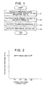
- Fig. 2 is a characteristic diagram showing a relation between a polarization resistance R and an open-circuit voltage Voc measured as the parameters by the method according to this example
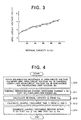
- Fig. 3 is a characteristic diagram illustrating graphically changes of the open-circuit voltage Voc as a function of a residual capacity Cr.
- the parameter such as polarization resistance R which varies in dependence on the individual secondary batteries and which also varies as a function of the charge/discharge cycle repetition number NC can be measured without executing additionally any specific measurement mode during the charge/discharge process.
- it is required to measure and store a terminal voltage V, a charge/discharge current I and a charge/discharge time T of a secondary battery which is undergoing the charge/discharge process with the aid of a microcomputer system which incorporates an arithmetic unit for executing various arithmetic processings and a storage or memory for storing the results of the arithmetic processings as well as other data.
- a charge/discharge process is performed at least once for a secondary battery under measurement for arithmetically determining an integrated power PS, an integrated charge quantity QS and an integrating time interval TS from a start of the charge/discharge process to an end thereof (step S1 in Fig. 1).
- a mean terminal voltage Vm is arithmetically determined by dividing the integrated power PS by the integrated charge quantity QS, while a mean current Im is determined by dividing the integrated charge quantity QS by the integrating time interval TS (step S2).
- the mean terminal voltage Vm encompasses a mean terminal voltage Vcm in the charging process and a mean terminal voltage Vdm in the discharging process with the mean current Im encompassing a mean charge current Icm and a mean discharge current Idm.
- the polarization resistance R of the secondary battery is arithmetically determined by using a battery polarization resistance model on the basis of the mean terminal voltage Vcm in the charging process, the mean terminal voltage Vdm in the discharging process, the mean charge current Icm and the mean discharge current Idm (step S3).
- the battery polarization resistance model can be given in the form of a mathematical expression defining a relation among the mean terminal voltage Vm, the mean current Im and the polarization resistance R.
- the polarization resistance R can be regarded to be constant.
- the polarization resistance R can be determined as a function of the parameters such as the types of the secondary batteries, structures thereof, ambient temperature of the environment in which the battery is opened, and the charge/discharge history (e.g. charge/discharge cycle repetition number NC).
- the function defining the polarization resistance R is invariable regardless of the type of the secondary battery and the structure thereof so far as the change in the polarization resistance R of one and the same secondary battery is of concern.
- the function defining the polarization resistance R may be regarded to be constant in respect to the ambient temperature except for the case where the change of the ambient temperature is remarkable. Accordingly, or the conditions mentioned above, the polarization resistance R can be regarded to change as a function only of the charge/discharge cycle repetition number NC.
- the polarization resistance R may be regarded to be constant for practical applications so long as the variation of the ambient temperature lies within the range of ⁇ 5 °C (refer to Fig. 12). Accordingly, use of the simple secondary battery polarization resistance model given by the aforementioned expression (1) is usually accompanied with no problem.
- Vcm Vocm + R ⁇ Icm
- Vdm Vocm + R ⁇ Idm
- the mean open-circuit voltages Vocm in the charging and discharging processes can be regarded to be equal to each other, wherein the mean terminal voltage Vcm in the charging process is usually higher than the mean open-circuit voltage Vocm while the mean terminal voltage Vdm in the discharging process is ordinarily lower than the mean open-circuit voltage Vocm.
- the polarization resistance R (Vcm - Vdm) / (Icm + Idm)
- the value of the polarization resistance R obtained from the expression (2) is stored in the memory to be used in the measurement of the open-circuit voltage Voc in the succeeding charge/discharge cycle.
- the open-circuit voltage Voc V ⁇ R ⁇ I
- the polarization resistance R and the open-circuit voltages Voc the typical parameters of the secondary battery, can easily and accurately be determined without resorting to interposition of any independent measurement mode, differing from the conventional methods described hereinbefore.
- the inventors of the present application experimentally conducted constant-current charge/discharge cycles by using a lithium ion type lithium secondary battery (of 2/3A size manufactured by the assignee of the present application) as the secondary battery to be tested and a charge/discharge testing apparatus commercially available under the trade name "HJ201B" from Hokuto Denkou Company of Japan. The results of this experiment will be elucidated below.
- the experiments were conducted on the following standard conditions. Namely, the upper limit open-circuit voltage VcL in the charging process is 4.2 V (volts), the lower limit open-circuit voltage VdL in the discharging process is 2.5 V, a predestinated charge current Ici of a predestinated charge/discharge current Ii is 100 mA (milliamperes), and a predestinated discharge current Idi is 200 mA.
- the terminal voltage V and the charge/discharge currents I of the lithium secondary battery during the charge/discharge processes were measured periodically at a time interval of 30 seconds by using a data logger commercially available under the trade name "TR2731" from Advantest Company and recorded on a magnetic disk.
- the integrated power PS, the integrated charge quantity QS and the integrating time interval TS were arithmetically determined by using a personal computer commercially available under the trade name "PC-9801VM11" from NEC Corporation of Japan.
- the mean terminal voltage Vm was calculated by dividing the integrated power PS by the integrated charge quantity QS, and the mean current Im was calculated by dividing the integrated charge quantity QS by the integrating time TS.
- the mean terminal voltage Vcm in the charging process the mean terminal voltage Vdm in the discharging process, the mean charge current Icm and the mean discharge current Idm, the polarization resistance R was determined in accordance with the expression (2) mentioned previously, while the open-circuit voltage Voc was determined in accordance with the expression (3).
- the conventional parameter measuring method was experimentally carried out by using the aforementioned lithium ion type lithium secondary battery.
- the charge/discharge cycle test was performed for measuring the open-circuit voltage Voc and the polarization resistance R on the same test conditions as mentioned previously except for interposition of a pause or interruption period of ten minutes upon every lapse of ten minutes in the course of the charge/discharge process.
- this conventional parameter measuring method will be referred to as the interruption method.
- the open-circuit voltage Voc can be determined through linear approximation by plotting the change of the terminal voltage V recorded during the interruption time period as a reciprocal of the time. More specifically, the voltage at the zero point on the time reciprocal axis is determined as the open-circuit voltage Voc.
- the polarization resistance R can then be determined by dividing a difference between the open-circuit voltage Voc as obtained and the terminal voltage V measured immediately preceding to the interruption by the charge/discharge current I.
- Figure 2 shows R-versus-I characteristics of the lithium secondary battery obtained by plotting the polarization resistance R as a function of the charge/discharge current I in accordance with the parameter measuring method according this example and the conventional interruption method, respectively, wherein a solid-line curve represents the characteristic according to this example with a broken-line curve representing that of the conventional method.
- Figure 3 shows Voc-versus-Cr characteristics obtained by plotting the residual capacity Cr of the lithium secondary battery as a function of the open-circuit voltage Voc in accordance with the parameter measuring method of this example and the conventional interruption method in which a solid-line curve represents the characteristic of the lithium secondary battery measured according to this example with a broken-line curve representing the corresponding characteristic measured by the conventional interruption method.
- the example described above is directed to the determination of the parameters of the secondary battery such as the polarization resistance R and the open-circuit voltage Voc.
- a charge/discharge control method of the secondary battery for extending the life cycle number or the effective charge/discharge cycle repeatable number NL defined previously on the basis of the polarization resistance R and the open-circuit voltage Voc measured by the parameter measuring method according to the example described above together with an upper limit open-circuit voltage VcL in the charging process, a lower limit open-circuit voltage VdL in the discharging process and a polarization limit voltage dEL whose values are previously set.
- the predestinated charge/discharge current Ii is so controlled that the charge/discharge control voltage VC given by a product of the predestinated charge/discharge current Ii and the polarization resistance R does not exceed the polarization limit voltage dEL.
- the charge/discharge control voltage VC is an overvoltage which can be predicted on the basis of the predestinated charge/discharge current Ii.
- the charge/discharge control voltage VC coincides with the overvoltage which is represented by a difference between the open-circuit voltage Voc and the terminal voltage V.
- the polarization limit voltage dEL represents an upper limit voltage regardless of whether the charging process or the discharging process is of concern, because the polarization voltage Vp is given as an absolute value of a difference between the open-circuit voltage Voc and the terminal voltage V.
- the charge/discharge of the secondary battery is terminated within a charge/discharge time T which is so determined by using the predestinated charge/discharge current Ii and the residual capacity Cr determined on the basis of the open-circuit voltage Voc that the open-circuit voltage Voc is prevented from lowering below the lower limit open-circuit voltage VdL during the discharge process while during the charging process, the open-circuit voltage Voc does not increase beyond the upper limit open-circuit voltage VcL.
- Figure 4 is a flow chart for illustrating the charge/discharge control method according to the first embodiment of the invention.
- the preset values of the upper limit open-circuit voltage VcL in the charging process, the lower limit open-circuit voltage VdL in the discharging process and the polarization limit voltage dEL are experimentally determined in dependence on the types of the secondary batteries.
- VcL 4.2 V
- the preset values as mentioned above are not always same intrinsically for all the lithium secondary batteries of the lithium ion type because they may differ in respect to the material as used in manufacturing. In actually, a variety of materials or substances have heretofore been proposed for use in the lithium secondary batteries of the lithium ion type.
- the residual capacity Cr is calculated on the basis of the open-circuit voltage Voc in a step S12, whereupon the residual charge/discharge time Tr is calculated from the residual capacity Cr and the predestinated charge/discharge current Ii in a step S13.
- the relation between the open-circuit voltage Voc and the residual capacity Cr is also experimentally determined.
- the absolute capacity of the secondary battery assumes different values at the beginning and at the end of the charge/discharge cycle even when the open-circuit voltage Voc remains at a same level.
- the above expression (4) applies valid equally in the discharging process of the secondary battery.
- the absolute capacity Ca in the discharging process can be determined by replacing the charge capacity Cc by the discharge capacity Cd in the expression (4).
- step S14 the charge/discharge process of the secondary battery is ended within the residual charge/discharge time Tr determined so that the open-circuit voltage Voc does not lower below the lower limit open-circuit voltage VdL during the discharging process and that the open-circuit voltage Voc does not exceed the upper limit open-circuit voltage VcL during the charging process.
- Fig. 5 shows a charge/discharge test apparatus
- Fig. 6 illustrates graphically a relation between the discharge capacity Cd and the charge/discharge cycle repetition number NC.
- the charge/discharge test apparatus is comprised of a controller 1 including a central processing unit or CPU, a memory and others, a load 10 to which an electric power is supplied under the control of the controller 1, a secondary battery 12 for supplying an electric power to the load 10, a constant-current power source 14 for supplying a constant current to the load 10 and the secondary battery 12 under the control of the controller 1, an ampere meter 15 inserted between the secondary battery 12 and the constant-current power source 14 for detecting the charge/discharge current I and a voltmeter 16 connected between both electrode terminals of the secondary battery 12.
- the charge/discharge current I and the terminal voltage V of the secondary battery 12 as detected by the ampere meter 15 and the voltmeter 16, respectively, are inputted to the controller 1 as the data.
- the secondary battery 12 undergone the test was a lithium secondary battery of lithium ion type (manufactured by the assignee of the present application). Further, as the constant current source constituting the charge/discharge testing apparatus together with the controller 1, a constant current source commercially available under the trade name "PAX16-20" from Kikusui Electronic Company of Japan was used. Additionally, as the load 10, an electric consumption device commercially available under the trade name "PLZ-153W" from the above company was used, while as the controller 1 for controlling the charge/discharge process, a personal computer commercially available under the trade name "PC-9801DA" from NEC Corporation was employed.
- the upper limit open-circuit voltage VcL in the charging process was set at 4.2 volts
- the lower limit open-circuit voltage VdL in the discharging process was set at 2.5 volts
- the predestinated charge current Ici was set at 100 mA
- the predestinated discharge current Idi was set at 200 mA.
- the charge/discharge cycle test was conducted by adopting the charge/discharge control method described hereinbefore by reference to Fig. 4.
- the discharge current Cd in the charge/discharge cycle becomes significantly low as the charge/discharge cycle repetition number NC increases in the case of the conventional control method (see the broken-line curve).
- the discharge current Cd in charge/discharge cycle can maintain a high capacity over an extended period because the secondary battery can be charged sufficiently without being accompanied with overcharge in the case of the charge/discharge control method according to the instant embodiment of the invention.
- the first embodiment of the invention it is aimed to extend or lengthen the life of the secondary battery 12 by controlling it by using the parameters measured by the method according to the example described in connection with Figs. 1-3. However, it is equally possible to estimate the life of the secondary battery 12 by using these measured parameters.
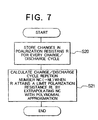
- a step S20 the polarization resistance R calculated in the step S3 mentioned previously (see Fig. 1) is fetched for storing the changes of the polarization resistance R in every charge/discharge cycle of the secondary battery 12.
- a polynomial approximating extrapolation based on a method of least squares is performed on the charge/discharge cycle repetition number NC of the secondary battery 12 to thereby determine as the effective charge/discharge cycle repeatable number (life or life cycle number) NL of the secondary battery 12 as expected the charge/discharge cycle repetition number NC at a time point when the polarization resistance R has attained the limit polarization resistance RL set previously in a step S21.
- the preset value of the limit polarization resistance RL may change in dependence on the definition of the effective charge/discharge cycle repeatable number NL and the expected mean current Im.
- the life of the secondary battery as a life span during which the initial capacity (100 %) of the secondary battery progressively falls to 70 % thereof.
- the charge/discharge process was repeated until the discharge current Cd has attained a value corresponding to 70 % of the design capacity (100 %).
- the terminal voltage V and the charge/discharge currents I of the secondary battery 12 were measured during the charge/discharge processes periodically at a time interval of 30 seconds by using a data logger "TR2731" manufactured by Advantest Company, the results of the measurements being recorded on a magnetic disk.
- the integrated power PS, the integrated charge quantity QS and the integrating time interval TS were calculated for every charge/discharge cycle, whereon the mean terminal voltage Vm was determined by dividing the integrated power PS by the integrated charge quantity QS, while determining the mean current Im by dividing the integrated charge quantity QS by the integrating time interval TS.
- the polarization resistance R and the open-circuit voltage Voc were determined in accordance with the aforementioned expressions (2) and (3), respectively.
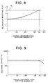
- Figure 8 is a characteristic diagram for graphically illustrating the change in the polarization resistance R of the two secondary batteries 12 which differ from each other in respect to the amount of the liquid electrolyte in every charge/discharge cycle.
- the limit polarization resistance RL is set at 3.5 ⁇ or so.
- a single-dotted curve represents the characteristic when the quantity of the liquid electrolyte is standard, while a broken-line curve and a solid-line curve represent the characteristics when the amount of liquid electrolyte is small, wherein the broken-line curve represents the results actually obtained by measuring over a period corresponding to the charge/discharge cycle repetition number NC ranging from 0 (zero) to 200, while the solid-line curve is obtained after the polynomial approximating extrapolation based on a method of least squares for the charge/discharge cycle repetition number NC ranging from 0 (zero) to 400.
- values of variables A0 to An are so determined that a square value of a deviation or difference between the characteristic (solid-line curve in Fig. 8) of the polarization resistance R predicted from the charge/discharge cycle repetition number NC and the characteristic of the polarization resistance R measured actually becomes minimum.
- the degree n of the polynomial (6) should ideally be set at a value smaller by one than the number of the data obtained by the actual measurement. However, for the practical purpose, the degree n equal to "5" at the greatest will be sufficient.
- the life cycle number or the effective charge/discharge cycle repeatable number NL of the secondary battery 12 can be predicted through the approximation based on the polynomial (6).
- Figure 9 is a characteristic diagram illustrating the change in the discharge capacity Cd as a function of the charge/discharge cycle repetition number NC ranging from 0 (zero) to 400, wherein a solid-line curve represents the characteristic for the secondary battery of a small amount of liquid electrolyte, while a single-dotted line represents the characteristic for the secondary battery containing a standard amount of liquid electrolyte.
- the discharge capacity Cd which corresponds to 70 % of the design capacity can no more be sustained when the charge/discharge cycle repetition number NC reaches or exceeds a number of about 350, resulting in lowering of the capacity in reality.
- Figure 10 is a block diagram showing a structure of a charge/discharge control apparatus according to a third embodiment of the invention.
- reference numerals 1, 10 and 12 denote parts same as or equivalent to those designated by the same numerals in Fig. 5 first embodiment).
- the controller 1 is comprised of an.input apparatus 2 including a keyboard and others, an analogue-to-digital or A/D converter 3 for fetching the measurement data concerning the secondary battery 12 such as the terminal voltage V and the charge/discharge current I to thereby convert them to respective digital signals, a central processing unit or CPU 4 to which various signals are supplied from the input apparatus 2 and the A/D converter 3, a timer 5 for supplying chronometric or time data to the CPU 4, a read-only memory or ROM 6 for storing programs and other information required for operating the CPU 4, a random-access memory or RAM 7 for storing data for or resulting from arithmetic operations executed by the CPU 4, a back-up magnetic disk 8 serving as an external storage means for the CPU 4, and a current control unit 9 connected to the CPU 4 for controlling a current (i.e., a predestinated charge/discharge current Ii) for the load 10 under the control of the CPU 4.
- a current i.e., a predestinated charge/discharge current
- the CPU 4 includes a measuring means for measuring the terminal voltage V, the charge/discharge current I and the charge/discharge time T of the secondary battery 12 in cooperation with a voltage/current detecting unit (described later on), a storage means for storing the terminal voltage V, the charge/discharge current I and the charge/discharge time T, a control means for controlling the predestinated charge/discharge current Ii flowing to/from the secondary battery 12, and an arithmetic means for arithmetically determining the open-circuit voltage Voc of the secondary battery 12, the polarization resistance R, the life cycle number or the effective charge/discharge cycle repeatable number NL, the residual charge/discharge time Tr and the charge/discharge control voltage VC in cooperation with the current control unit 9 on the basis of the terminal voltage V, the charge/discharge current I, the predestinated charge/discharge current Ii and the charge/discharge time T.
- a voltage/current detecting unit described later on
- a storage means for
- the voltage/current detecting unit 19 corresponds to the ampere meter 15 and the volt meter 16 mentioned hereinbefore (refer to Fig. 5) and serves to detect the terminal voltage V and the charge/discharge current I of the secondary battery 12.
- the voltage/current detecting unit 19 constitutes a measuring means in cooperation with the CPU 4 incorporated in the controller 1.
- the terminal voltage V and the charge/discharge current I measured by the voltage/current detecting unit 19 between the secondary battery 12 and the current control unit 9 are supplied to the CPU 4 via the A/D converter 3.
- the arithmetic means incorporated in the CPU 4 calculates the integrated power PS, the integrated charge quantity QS and the integrating time interval TS mentioned previously by using the data concerning the time supplied from the timer 5 and the terminal voltage V as well as the charge/discharge current I supplied from the A/D converter 3. The results of the calculation are written in the polarization resistance RAM 7 and the back-up magnetic disk 8.
- the arithmetic means incorporated in the CPU 4 reads out the data stored in the back-up magnetic disk 8 onto the RAM 7 to thereby calculate the open-circuit voltage Voc on the basis of the polarization resistance R in the immediately preceding cycle as contained in the data read out onto the RAM 7 and the terminal voltage V as well as the charge/discharge current I detected currently. The results of the calculation are written into the RAM 7 and the back-up magnetic disk 8.
- the above-mentioned arithmetic means compares the open-circuit voltage Voc with the lower limit open-circuit voltage VdL in the discharging process and the upper limit open-circuit voltage VcL in the charging process to thereby determine whether the conditions given by the following expression is satisfied or not.
- the predestinated charge/discharge current Ii which is to flow to or from the secondary battery 12 is determined, whereupon the charge/discharge current I is so controlled that the current control unit 9 coincides with the predestinated charge/discharge current Ii.
- the current control unit 9 constituting the control means in cooperation with the CPU 4 controls the current to be supplied to the load 10 from the secondary battery 12 or the predestinated charge current Ii to be supplied to the secondary battery 12 from the charging power source 11.
- the CPU 4 calculates the up-to-date polarization resistance R to thereby replace the polarization resistance R stored in the polarization resistance RAM 7 by the up-to-date value. Similarly, the corresponding data stored in the back-up magnetic disk 8 is equally updated.
- the arithmetic means incorporated in the CPU 4 performs the polynomial approximating extrapolation based on a method of least squares in accordance with the expression (6) to thereby calculate the effective charge/discharge cycle repeatable number (life cycle number) NL.
- the CPU 4 may be so arranged as to execute the arithmetic processings mentioned above on a time division basis or in parallel.
- the upper limit open-circuit voltage VcL in the charging process, the lower limit open-circuit voltage VdL in the discharging process, the polarization limit voltage dEL and the limit polarization resistance RL adopted as the control conditions are inputted, for example, by using a keyboard of the input apparatus 2 to be stored in the RAM 7 and the back-up magnetic disk 8.
- the overcharge which causes the open-circuit voltage to exceed the upper limit open-circuit voltage VcL in the charging process as well as the overdischarge which causes the open-circuit voltage to lower below the lower limit open-circuit voltage VdL in the discharging process can positively prevented from occurring during the charge/discharge control of the secondary battery 12, even when the value of the polarization resistance R intrinsic to the secondary battery 12 varies during the charge/discharge cycle.
- the upper limit open-circuit voltage VcL in the charging process is set fixedly at 4.2 volts
- the lower limit open-circuit voltage VdL in the discharging process is set at 0.5 volt
- the limit polarization resistance RL is set fixedly at 3.5 ohms.
- Figure 11 is a block diagram showing an electric power storage apparatus according to a fifth embodiment of the present invention.
- reference numerals 1, 9 and 12 denote parts same as or equivalent to those designated by like reference numerals in the preceding embodiments.
- a battery assembly 120 is constituted by a plurality of individual secondary batteries 12 (e.g. sixty secondary batteries) connected in series to one another.
- a parameter arithmetic unit 20 is provided for arithmetically determining the polarization resistance R and the open-circuit voltage Voc on the basis of the charge/discharge current I and the terminal voltage V detected from a given one secondary battery 12 of the battery assembly 120.
- the parameter arithmetic unit 20 is constituted by the CPU 4, the RAM 7 and others (see Fig. 10).
- detecting means for detecting the terminal voltage V and the charge/discharge current I are provided, respectively, in association with the output terminal of the secondary battery 12, although the detecting means is omitted from illustration.
- An inverter 21 is provided for converting a DC power and an AC power to each other.
- the inverter 21 is connected to the current control unit 9 incorporated in the controller 1.
- a protective device 22 is provided in association with the inverter 21 for inhibiting excessive power supply to the inverter 21.
- An AC power supply network i.e., an AC (alternating current) grid 23 is connected to the protective device 22, wherein the AC power of a commercial AC source is supplied to the inverter 21 via the protective device 22.
- the AC grid 23 also serves as a load to which the AC power outputted from the inverter 21 is supplied via the protective device 22.
- the inverter 21 converts an AC power supplied from the AC grid 23 into a DC power which is then stored in the battery assembly 120 constituted by a plurality of secondary batteries 12. On the other hand, the DC power stored in the battery assembly 120 is converted into an AC power by the inverter 21 to be supplied to the AC grid 23.
- the controller 1 serves as the charge/discharge control apparatus of the electric energy storage apparatus.
- the inverter 21 converts the midnight AC power to a DC power to be stored in the battery assembly 120 via the current control unit 9.
- the DC power stored in the battery assembly 120 is converted to the AC power by the inverter to be supplied to the AC grid 23 now functioning as a load.
- the parameter arithmetic unit 20 incorporated in the controller 1 measures the terminal voltage V and the charge/discharge current I of one secondary battery 12 selected arbitrarily from the battery assembly 120, whereon the parameter arithmetic unit 20 arithmetically determines the polarization resistance R and the open-circuit voltage Voc on the basis of the terminal voltage V and the charge/discharge current I to thereby allow the current control unit 9 to perform the control described previously.
- the lithium ion type lithium secondary batteries each having a capacity of e.g. 70 Ah (ampere-hour) is employed as the individual secondary batteries which constitute the battery assembly 120, while the charge/discharge control apparatus dedicated only to the control of the lithium secondary battery is employed as the controller 1 for controlling the battery assembly 120.
- the electric power storage enjoying high efficiency can be implemented without impairing the use life of the secondary battery 12.
- the charge/discharge control can be accomplished on the basis of the polarization resistance R and the open-circuit voltage Voc which can easily be measured, the charge/discharge cycle life NC of the secondary battery 12 (inter alia the life of the lithium secondary battery) can be extended.
- control conditions mentioned hereinbefore are determined on the assumption that the secondary battery 12 is the lithium ion type lithium secondary battery. It goes without saying that these control conditions may be altered in dependence on the types of the secondary battery 12 or in consideration of improvement of performances of the secondary battery 12 in the future. Thus, even when the secondary battery 12 of different types are of concern or when the performance of the secondary battery is improved or enhanced, this can easily be coped with by changing correspondingly the control conditions or by exchanging the ROM 6 storing fixedly these control conditions with an updated one.
Landscapes
- Physics & Mathematics (AREA)
- General Physics & Mathematics (AREA)
- Engineering & Computer Science (AREA)
- Power Engineering (AREA)
- Secondary Cells (AREA)
- Charge And Discharge Circuits For Batteries Or The Like (AREA)
Description
Claims (3)
- A charge/discharge control apparatus for a secondary battery, comprising:wherein said control means (9) is adapted to control said predestinated charge/discharge current (Ii) such that said charge/discharge control voltage (VC) does not exceed a polarization limit voltage (dEL), anda measuring means (19) for measuring a terminal voltage (V), a charge/discharge current (I) and a charge/discharge time (T) of a secondary battery (12);memory means (7, 8) for storing said terminal voltage (V), said charge/discharge current (I) and said charge/discharge time (T);control means (9) for controlling a predestinated charge/discharge current (Ii) which is to flow to/from said secondary battery (12); andarithmetic means (4; 20) for arithmetically determining an open-circuit voltage (Voc), a polarization resistance (R) thereof, a life cycle number (NL), a residual charge/discharge time (Tr) and a charge/discharge control voltage (VC), respectively, of said secondary battery (12) on the basis of said terminal voltage (V), said charge/discharge current (I), said predestinated charge/discharge current (i) and said charge/discharge time (T),
said control means (9) is adapted to control said charge/discharge current (I) such that said charge/discharge current (I) coincides with said predestinated charge/discharge current (Ii). - A secondary battery control apparatus according to claim 1,
wherein said secondary battery (12) is a lithium secondary battery. - An apparatus for storing electric energy, comprising a charge/discharge control apparatus according to claim 1; and
electric power conversion means (21) for converting an AC electric power into a DC power, for storing said DC power in said secondary battery (12).
Applications Claiming Priority (3)
| Application Number | Priority Date | Filing Date | Title |
|---|---|---|---|
| JP06271376A JP3121732B2 (en) | 1994-11-04 | 1994-11-04 | Secondary battery parameter measurement method, secondary battery charge / discharge control method and life prediction method using the same, secondary battery charge / discharge control device, and power storage device using the same |
| JP27137694 | 1994-11-04 | ||
| EP95115663A EP0711016B1 (en) | 1994-11-04 | 1995-10-04 | Parameter measuring method, charge/discharge control method and apparatus and life predicting method for secondary batteries and power storage apparatus using the same |
Related Parent Applications (2)
| Application Number | Title | Priority Date | Filing Date |
|---|---|---|---|
| EP95115663A Division EP0711016B1 (en) | 1994-11-04 | 1995-10-04 | Parameter measuring method, charge/discharge control method and apparatus and life predicting method for secondary batteries and power storage apparatus using the same |
| EP95115663.7 Division | 1995-10-04 |
Publications (2)
| Publication Number | Publication Date |
|---|---|
| EP1049231A1 EP1049231A1 (en) | 2000-11-02 |
| EP1049231B1 true EP1049231B1 (en) | 2004-02-04 |
Family
ID=17499212
Family Applications (2)
| Application Number | Title | Priority Date | Filing Date |
|---|---|---|---|
| EP95115663A Expired - Lifetime EP0711016B1 (en) | 1994-11-04 | 1995-10-04 | Parameter measuring method, charge/discharge control method and apparatus and life predicting method for secondary batteries and power storage apparatus using the same |
| EP00113479A Expired - Lifetime EP1049231B1 (en) | 1994-11-04 | 1995-10-04 | Parameter measuring method, charge/discharge control method and apparatus and life predicting method for secondary batteries and power storage apparatus using the same |
Family Applications Before (1)
| Application Number | Title | Priority Date | Filing Date |
|---|---|---|---|
| EP95115663A Expired - Lifetime EP0711016B1 (en) | 1994-11-04 | 1995-10-04 | Parameter measuring method, charge/discharge control method and apparatus and life predicting method for secondary batteries and power storage apparatus using the same |
Country Status (4)
| Country | Link |
|---|---|
| US (1) | US5672951A (en) |
| EP (2) | EP0711016B1 (en) |
| JP (1) | JP3121732B2 (en) |
| DE (2) | DE69529597T2 (en) |
Families Citing this family (90)
| Publication number | Priority date | Publication date | Assignee | Title |
|---|---|---|---|---|
| US6831848B2 (en) | 1994-04-26 | 2004-12-14 | Comarco Wireless Technologies, Inc. | Programmable power supply to simultaneously power a plurality of electronic devices |
| US5949213A (en) * | 1994-04-26 | 1999-09-07 | Comarco Wireless Technologies, Inc. | Method and system for charging rechargeable batteries |
| US6693413B1 (en) | 1994-04-26 | 2004-02-17 | Comarco Wireless Technologies, Inc. | Programmable power supply |
| US7145787B2 (en) * | 1994-04-26 | 2006-12-05 | Comarco Wireless Technologies, Inc. | Programmable power supply |
| DE19643012B4 (en) * | 1996-10-18 | 2008-01-03 | Vb Autobatterie Gmbh & Co. Kgaa | Method for charging an electrical accumulator with a generator |
| US5789924A (en) * | 1997-03-20 | 1998-08-04 | Sanyo Electric Co., Ltd. | Method of calculating rechargeable battery charge capacity |
| US6023151A (en) * | 1998-03-16 | 2000-02-08 | Eveready Battery Company, Inc. | Method and device for enhancing smart battery performance |
| US5990664A (en) * | 1998-03-30 | 1999-11-23 | Eveready Battery Company, Inc. | Process and apparatus for modulating terminal voltage of battery |
| CN1199050C (en) * | 1998-05-28 | 2005-04-27 | 丰田自动车株式会社 | Means for estimating charged state of battery and method for estimating degraded state of battery |
| KR20010072026A (en) * | 1998-07-20 | 2001-07-31 | 크리스 로저 에이취. | System and method for monitoring a vehicle battery |
| JP2000166103A (en) * | 1998-12-01 | 2000-06-16 | Sanyo Electric Co Ltd | Charging discharging control method |
| NZ513579A (en) * | 1999-01-18 | 2001-09-28 | Farnow Technologies Pty Ltd | Energy gauge |
| JP4491849B2 (en) * | 1999-03-05 | 2010-06-30 | ソニー株式会社 | Battery cell charge / discharge number detection device and battery cell charge / discharge number detection method |
| US6242886B1 (en) | 1999-04-12 | 2001-06-05 | Alliedsignal Inc. | Apparatus and method for automatic recovery of sulfated lead acid batteries |
| KR100354243B1 (en) * | 1999-04-21 | 2002-09-28 | 삼성에스디아이 주식회사 | Method for generating data for monitoring and controlling states of charge and discharge of secondary battery |
| EP1923710B1 (en) | 1999-09-09 | 2010-10-27 | Toyota Jidosha Kabushiki Kaisha | Battery capacity measuring and remaining capacity calculating system |
| US6215312B1 (en) | 1999-11-09 | 2001-04-10 | Steven Hoenig | Method and apparatus for analyzing an AgZn battery |
| US6166523A (en) * | 2000-01-11 | 2000-12-26 | Honeywell International Inc. | Smart alternator method and apparatus for optimizing fuel efficiency and monitoring batteries in an automobile |
| US6507171B2 (en) * | 2000-12-29 | 2003-01-14 | Nokia Corporation | Method and apparatus for measuring battery charge and discharge current using a direct analog-to-digital conversion of a charge/discharge replica current |
| US6407532B1 (en) | 2000-12-29 | 2002-06-18 | Nokia Mobile Phones, Ltd. | Method and apparatus for measuring battery charge and discharge current |
| GB0102276D0 (en) * | 2001-01-29 | 2001-03-14 | Lucas Industries Ltd | Method of and apparatus estimating the state of charge of a battery |
| JP4691796B2 (en) * | 2001-02-14 | 2011-06-01 | ソニー株式会社 | Charging / discharging device and method, power supply device and method, power supply system and method, program storage medium, and program |
| JP4215152B2 (en) * | 2001-08-13 | 2009-01-28 | 日立マクセル株式会社 | Battery capacity detection method |
| JP4097182B2 (en) * | 2001-12-27 | 2008-06-11 | パナソニックEvエナジー株式会社 | Secondary battery polarization voltage estimation method, secondary battery remaining capacity estimation method and apparatus, and battery pack system |
| US7400149B2 (en) | 2002-01-08 | 2008-07-15 | Siemens Aktiengesellschaft | Method for assessment of the state of batteries in battery-supported power supply systems |
| DE10201136C1 (en) * | 2002-01-08 | 2003-06-05 | Siemens Ag | Assessing state of batteries in battery back up power supply systems involves repeating discharge cycle at fixed times to record current discharge characteristic for residual voltage |
| FR2835923B1 (en) * | 2002-02-13 | 2004-05-14 | Peugeot Citroen Automobiles Sa | SYSTEM FOR DETERMINING THE STATE OF CHARGE OF A BATTERY, PARTICULARLY FOR A MOTOR VEHICLE |
| US7190171B2 (en) | 2002-10-11 | 2007-03-13 | Canon Kabushiki Kaisha | Detecting method and detecting apparatus for detecting internal of rechargeable battery, rechargeable battery pack having said detecting apparatus therein, apparatus having said detecting apparatus therein, program in which said detecting method is incorporated, and medium in which said program is stored |
| US6836101B2 (en) | 2002-12-05 | 2004-12-28 | Comarco Wireless Technologies, Inc. | Tip having active circuitry |
| JP3714333B2 (en) * | 2003-02-28 | 2005-11-09 | 日産自動車株式会社 | Secondary battery input / output possible power estimation device |
| DE10328721A1 (en) * | 2003-06-25 | 2005-01-13 | Robert Bosch Gmbh | Method for predicting a residual life of an electrical energy store |
| JP4010288B2 (en) | 2003-07-29 | 2007-11-21 | ソニー株式会社 | Secondary battery remaining capacity calculation method and battery pack |
| US7234552B2 (en) * | 2003-09-19 | 2007-06-26 | Ford Global Technologies, Llc | Method for heating a battery in a hybrid electric vehicle |
| US9153960B2 (en) | 2004-01-15 | 2015-10-06 | Comarco Wireless Technologies, Inc. | Power supply equipment utilizing interchangeable tips to provide power and a data signal to electronic devices |
| JP3897027B2 (en) | 2004-03-16 | 2007-03-22 | ソニー株式会社 | Battery device and discharge control method for battery device |
| JP4874108B2 (en) * | 2004-08-05 | 2012-02-15 | パナソニック株式会社 | Nickel-hydrogen battery life determination method and life determination device |
| DE102005020356A1 (en) * | 2005-05-02 | 2006-11-09 | Robert Bosch Gmbh | Device, in particular charger device |
| JP2006325372A (en) * | 2005-05-20 | 2006-11-30 | Shimano Inc | Dc power supply unit for human-powered vehicle |
| JP4888041B2 (en) * | 2006-02-16 | 2012-02-29 | 株式会社デンソー | Battery voltage regulator |
| JP4884945B2 (en) * | 2006-11-30 | 2012-02-29 | 三菱重工業株式会社 | Charging state prediction program, overhead line-less traffic system and charging method thereof |
| CN101772709B (en) * | 2007-12-13 | 2012-11-14 | 松下电器产业株式会社 | Lifetime estimating method and deterioration suppressing method for lithium secondary cell, lifetime estimator and deterioration suppressor, battery pack using the same, and charger |
| TW200933181A (en) * | 2008-01-30 | 2009-08-01 | Inventec Appliances Corp | A method for estimating lithium battery lifetime of portable electronic products |
| CN102007420A (en) * | 2008-04-16 | 2011-04-06 | 皇家飞利浦电子股份有限公司 | Method and device for predicting a rechargeable battery's lifetime |
| JP4473944B2 (en) * | 2008-08-07 | 2010-06-02 | パナソニック株式会社 | Lead storage battery control method and power supply system |
| US8213204B2 (en) | 2009-04-01 | 2012-07-03 | Comarco Wireless Technologies, Inc. | Modular power adapter |
| GB0913770D0 (en) | 2009-08-06 | 2009-09-16 | Eh Europe Gmbh | A method and apparatus for charging a lead acid battery |
| GB0913769D0 (en) * | 2009-08-06 | 2009-09-16 | Eh Europe Gmbh | A method and apparatus for charging a battery |
| DE102009042656A1 (en) | 2009-09-23 | 2011-03-24 | Bayerische Motoren Werke Aktiengesellschaft | Method for controlling or regulating at least one operating parameter influencing the aging state of an electrical energy store |
| JP5633227B2 (en) * | 2009-10-14 | 2014-12-03 | ソニー株式会社 | Battery pack and battery pack deterioration detection method |
| US8354760B2 (en) | 2009-10-28 | 2013-01-15 | Comarco Wireless Technologies, Inc. | Power supply equipment to simultaneously power multiple electronic device |
| JP5496612B2 (en) * | 2009-11-11 | 2014-05-21 | 三洋電機株式会社 | Battery chargeable / dischargeable current calculation method, power supply device, and vehicle equipped with the same |
| NL2003923C2 (en) * | 2009-12-08 | 2011-06-09 | Epyon B V | Method and device for testing an electric energy storage component. |
| AU2010354957B2 (en) | 2010-06-07 | 2014-04-17 | Mitsubishi Electric Corporation | Charge status estimation apparatus |
| JP2012018037A (en) * | 2010-07-07 | 2012-01-26 | Nec Energy Devices Ltd | Voltage measuring circuit and method |
| GB2498103B (en) * | 2010-10-26 | 2016-03-30 | Hewlett Packard Development Co | Backup power supply systems and methods |
| US9354277B2 (en) * | 2010-10-29 | 2016-05-31 | Gm Global Technology Operatins Llc | Apparatus of SOC estimation during plug-in charge mode |
| US9229510B2 (en) * | 2010-11-25 | 2016-01-05 | Industrial Technology Research Institute | Power management method for electro-chemical batteries in low capacity state |
| TWI428622B (en) * | 2010-11-25 | 2014-03-01 | Ind Tech Res Inst | Method for checking and modulating battery capacity and power based on battery charging/discharging characteristics |
| TWI412775B (en) * | 2011-01-17 | 2013-10-21 | Hon Hai Prec Ind Co Ltd | System and method for testing reliability of battery charging and discharging |
| JP2012155981A (en) * | 2011-01-26 | 2012-08-16 | Hitachi Consumer Electronics Co Ltd | Storage battery managing system, and recycle equipment and management server to be applied therein |
| US8901894B2 (en) | 2011-04-18 | 2014-12-02 | Renesas Electronics America Inc. | Battery management control method |
| CN102520366B (en) * | 2011-12-23 | 2014-11-12 | 上海交通大学 | Electric car cell safety and health assessment system and method thereof |
| CN102520365B (en) * | 2011-12-23 | 2015-10-14 | 上海交通大学 | Fast battery remaining capacity estimation system and method thereof |
| JP5783122B2 (en) * | 2012-04-11 | 2015-09-24 | トヨタ自動車株式会社 | Battery state estimation device |
| JP2014085118A (en) * | 2012-10-19 | 2014-05-12 | Toyota Motor Corp | Electricity storage system and abnormality discrimination method |
| JP5936708B2 (en) | 2012-11-29 | 2016-06-22 | 三菱電機株式会社 | Battery internal state estimation device |
| TWI473323B (en) | 2012-12-13 | 2015-02-11 | Ind Tech Res Inst | Charging method for charging battery and related charging structure |
| JP5708668B2 (en) | 2013-01-18 | 2015-04-30 | トヨタ自動車株式会社 | Power storage system |
| WO2014117846A1 (en) * | 2013-01-31 | 2014-08-07 | Statoil Petroleum As | A method of plugging a well |
| CN103293487B (en) * | 2013-06-28 | 2015-09-09 | 哈尔滨工业大学 | Based on the lithium ion battery life-span prediction method of integrated model |
| CN103516035B (en) * | 2013-10-24 | 2015-05-20 | 王春生 | Power transformer and control method thereof |
| TWI511409B (en) * | 2013-11-26 | 2015-12-01 | Ind Tech Res Inst | Power management method, apparatus and chip and non-transitory computer readable recording medium |
| US20150226807A1 (en) * | 2014-02-12 | 2015-08-13 | Seeo, Inc | Determination of nominal cell resistance for real-time estimation of state-of-charge in lithium batteries |
| JP2015155859A (en) * | 2014-02-21 | 2015-08-27 | ソニー株式会社 | Battery residual amount estimation device, battery pack, power storage device, electric vehicle and battery residual amount estimation method |
| CN104166101B (en) * | 2014-08-18 | 2017-09-22 | 广东欧珀移动通信有限公司 | A kind of method and device of Dynamic Announce battery capacity of mobile terminal |
| KR101783919B1 (en) * | 2014-10-31 | 2017-10-10 | 주식회사 엘지화학 | Apparatus and method for estimating open circuit voltage |
| JP6498920B2 (en) * | 2014-12-02 | 2019-04-10 | 古河電気工業株式会社 | Secondary battery state detection device and secondary battery state detection method |
| JP6311616B2 (en) * | 2015-01-14 | 2018-04-18 | 株式会社豊田自動織機 | Charging current control device and charging current control method |
| CN104698253A (en) * | 2015-03-16 | 2015-06-10 | 绍兴安卡汽车配件有限公司 | Determination method of lithium battery open circuit voltage |
| KR102014451B1 (en) | 2015-11-13 | 2019-08-26 | 주식회사 엘지화학 | System of Adjusting Power Parameter of Secondary Battery and Method thereof |
| CN105388427B (en) * | 2015-12-18 | 2018-06-01 | 天能电池集团有限公司 | A kind of frock and monitoring method for being used to monitor pole group pressure change in battery charge and discharge process |
| JP6615011B2 (en) * | 2016-03-09 | 2019-12-04 | 日立オートモティブシステムズ株式会社 | Battery management system, battery system and hybrid vehicle control system |
| CN106199434B (en) * | 2016-06-23 | 2019-12-10 | 矽力杰半导体技术(杭州)有限公司 | Battery and battery pack state detection method and device |
| CN106785136A (en) * | 2016-12-22 | 2017-05-31 | 深圳市金立通信设备有限公司 | The method and terminal of a kind of safe charging |
| CN107234982B (en) * | 2017-08-14 | 2019-05-07 | 成都雅骏新能源汽车科技股份有限公司 | A kind of power battery charging method based on big data statistics |
| CN108061863A (en) * | 2017-12-13 | 2018-05-22 | 宁德时代新能源科技股份有限公司 | Method and device for detecting battery, computer readable storage medium and battery management system |
| KR102458526B1 (en) * | 2018-02-07 | 2022-10-25 | 주식회사 엘지에너지솔루션 | Apparatus and method for estimating soc base on operating state of battery |
| CN109100652B (en) * | 2018-06-05 | 2022-04-26 | 中国电力科学研究院有限公司 | Method and system for predicting dispersion of power battery used in echelon |
| CN110085934B (en) * | 2019-05-30 | 2020-09-01 | 维沃移动通信有限公司 | Charging method of terminal battery and mobile terminal |
| CN113655399B (en) * | 2021-08-16 | 2024-04-16 | 国网湖南省电力有限公司 | Intelligent perception terminal battery power consumption life detection method and system |
Family Cites Families (12)
| Publication number | Priority date | Publication date | Assignee | Title |
|---|---|---|---|---|
| JPS61170678A (en) * | 1985-01-25 | 1986-08-01 | Nissan Motor Co Ltd | Battery state detector |
| JPH0650340B2 (en) * | 1986-04-14 | 1994-06-29 | 株式会社日立製作所 | Life Diagnostic Device for Automotive Battery |
| US4968942A (en) * | 1988-10-14 | 1990-11-06 | Allied-Signal Inc. | Method for monitoring aircraft battery status |
| US5281919A (en) * | 1988-10-14 | 1994-01-25 | Alliedsignal Inc. | Automotive battery status monitor |
| US4876513A (en) * | 1988-12-05 | 1989-10-24 | Globe-Union Inc. | Dynamic state-of-charge indicator for a battery and method thereof |
| US4952862A (en) * | 1989-09-29 | 1990-08-28 | At&T Bell Laboratories | Apparatus and method for adaptively predicting battery discharge reserve time |
| JPH03163375A (en) * | 1989-11-22 | 1991-07-15 | Kyocera Corp | Residual capacity display system of secondary battery |
| US5274321A (en) * | 1991-01-18 | 1993-12-28 | Sony Corporation | Battery charger |
| US5325041A (en) * | 1991-08-09 | 1994-06-28 | Briggs James B | Automatic rechargeable battery monitoring system |
| US5352968A (en) * | 1992-05-28 | 1994-10-04 | Apple Computer, Inc. | Battery charge state determination |
| US5281920A (en) * | 1992-08-21 | 1994-01-25 | Btech, Inc. | On-line battery impedance measurement |
| FI96370C (en) * | 1992-10-01 | 1996-06-10 | Fps Power Systems Oy Ab | Method for checking the internal impedance of a backup power supply battery and a backup power supply |
-
1994
- 1994-11-04 JP JP06271376A patent/JP3121732B2/en not_active Expired - Fee Related
-
1995
- 1995-09-18 US US08/529,396 patent/US5672951A/en not_active Expired - Fee Related
- 1995-10-04 DE DE69529597T patent/DE69529597T2/en not_active Expired - Lifetime
- 1995-10-04 EP EP95115663A patent/EP0711016B1/en not_active Expired - Lifetime
- 1995-10-04 DE DE69532539T patent/DE69532539T2/en not_active Expired - Lifetime
- 1995-10-04 EP EP00113479A patent/EP1049231B1/en not_active Expired - Lifetime
Also Published As
| Publication number | Publication date |
|---|---|
| EP0711016A2 (en) | 1996-05-08 |
| JP3121732B2 (en) | 2001-01-09 |
| DE69532539D1 (en) | 2004-03-11 |
| EP0711016B1 (en) | 2003-02-12 |
| DE69529597T2 (en) | 2003-11-13 |
| DE69532539T2 (en) | 2004-12-16 |
| EP1049231A1 (en) | 2000-11-02 |
| JPH08140270A (en) | 1996-05-31 |
| US5672951A (en) | 1997-09-30 |
| EP0711016A3 (en) | 1997-01-02 |
| DE69529597D1 (en) | 2003-03-20 |
Similar Documents
| Publication | Publication Date | Title |
|---|---|---|
| EP1049231B1 (en) | Parameter measuring method, charge/discharge control method and apparatus and life predicting method for secondary batteries and power storage apparatus using the same | |
| CN109725266B (en) | Method and device for calculating SOH (state of health) of battery | |
| JP3285720B2 (en) | Method and apparatus for detecting deterioration of assembled battery | |
| US6469512B2 (en) | System and method for determining battery state-of-health | |
| US6930485B2 (en) | Electronic battery tester with battery failure temperature determination | |
| US6157169A (en) | Monitoring technique for accurately determining residual capacity of a battery | |
| US8643331B1 (en) | Enhanced voltage-based fuel gauges and methods | |
| US5557189A (en) | Method and apparatus including a current detector and a power source control circuit for charging a number of batteries | |
| JP5074648B2 (en) | Secondary battery internal state detection method, detection device, device provided with the detection device, internal state detection program, and medium containing the program | |
| US4390841A (en) | Monitoring apparatus and method for battery power supply | |
| EP1754978A2 (en) | Remaining-battery-capacity estimating apparatus, remaining-battery-capacity estimating method, and remaining-battery-capacity estimating computer program | |
| US8502504B1 (en) | Model-based battery fuel gauges and methods | |
| CN112771708B (en) | Degradation degree of power storage element, power storage remaining amount detection device, and power storage element management unit | |
| EP2053414B1 (en) | Method and apparatus for detecting internal information of secondary battery | |
| CN1228540A (en) | Monitoring technique for accurately determining residual capacity of battery | |
| JP2002107427A (en) | Method for detecting residual capacity of secondary battery | |
| US6909261B2 (en) | Method for predicting the loading capability of an electrochemical element | |
| EP1853934B1 (en) | Capacity degradation determination in a lead acid battery method and apparatus | |
| JP2001332310A (en) | Capacity estimating method and deterioration judging apparatus for lithium ion cell and lithium ion cell pack | |
| CN100592099C (en) | Apparatus and method for charging battery cells | |
| EP1649538B1 (en) | Battery float management | |
| EP1751567B1 (en) | Method for determining the available energy of a lithium ion battery | |
| KR20140071060A (en) | Methods and apparatus for online determination of battery state of charge and state of health | |
| JP3649643B2 (en) | Lithium-ion battery capacity estimation method | |
| JP2001250590A (en) | Method for deciding deterioration of storage battery |
Legal Events
| Date | Code | Title | Description |
|---|---|---|---|
| PUAI | Public reference made under article 153(3) epc to a published international application that has entered the european phase |
Free format text: ORIGINAL CODE: 0009012 |
|
| AC | Divisional application: reference to earlier application |
Ref document number: 711016 Country of ref document: EP |
|
| AK | Designated contracting states |
Kind code of ref document: A1 Designated state(s): DE FR GB |
|
| 17P | Request for examination filed |
Effective date: 20001114 |
|
| AKX | Designation fees paid |
Free format text: DE FR GB |
|
| 17Q | First examination report despatched |
Effective date: 20020411 |
|
| GRAH | Despatch of communication of intention to grant a patent |
Free format text: ORIGINAL CODE: EPIDOS IGRA |
|
| GRAS | Grant fee paid |
Free format text: ORIGINAL CODE: EPIDOSNIGR3 |
|
| GRAA | (expected) grant |
Free format text: ORIGINAL CODE: 0009210 |
|
| AC | Divisional application: reference to earlier application |
Ref document number: 0711016 Country of ref document: EP Kind code of ref document: P |
|
| AK | Designated contracting states |
Kind code of ref document: B1 Designated state(s): DE FR GB |
|
| REG | Reference to a national code |
Ref country code: GB Ref legal event code: FG4D |
|
| REF | Corresponds to: |
Ref document number: 69532539 Country of ref document: DE Date of ref document: 20040311 Kind code of ref document: P |
|
| ET | Fr: translation filed | ||
| PLBE | No opposition filed within time limit |
Free format text: ORIGINAL CODE: 0009261 |
|
| STAA | Information on the status of an ep patent application or granted ep patent |
Free format text: STATUS: NO OPPOSITION FILED WITHIN TIME LIMIT |
|
| 26N | No opposition filed |
Effective date: 20041105 |
|
| PGFP | Annual fee paid to national office [announced via postgrant information from national office to epo] |
Ref country code: DE Payment date: 20131002 Year of fee payment: 19 Ref country code: FR Payment date: 20131009 Year of fee payment: 19 Ref country code: GB Payment date: 20131002 Year of fee payment: 19 |
|
| REG | Reference to a national code |
Ref country code: DE Ref legal event code: R119 Ref document number: 69532539 Country of ref document: DE |
|
| GBPC | Gb: european patent ceased through non-payment of renewal fee |
Effective date: 20141004 |
|
| PG25 | Lapsed in a contracting state [announced via postgrant information from national office to epo] |
Ref country code: GB Free format text: LAPSE BECAUSE OF NON-PAYMENT OF DUE FEES Effective date: 20141004 Ref country code: DE Free format text: LAPSE BECAUSE OF NON-PAYMENT OF DUE FEES Effective date: 20150501 |
|
| REG | Reference to a national code |
Ref country code: FR Ref legal event code: ST Effective date: 20150630 |
|
| PG25 | Lapsed in a contracting state [announced via postgrant information from national office to epo] |
Ref country code: FR Free format text: LAPSE BECAUSE OF NON-PAYMENT OF DUE FEES Effective date: 20141031 |