EP1049053A2 - Coin carrying device - Google Patents
Coin carrying device Download PDFInfo
- Publication number
- EP1049053A2 EP1049053A2 EP00303485A EP00303485A EP1049053A2 EP 1049053 A2 EP1049053 A2 EP 1049053A2 EP 00303485 A EP00303485 A EP 00303485A EP 00303485 A EP00303485 A EP 00303485A EP 1049053 A2 EP1049053 A2 EP 1049053A2
- Authority
- EP
- European Patent Office
- Prior art keywords
- coin
- carrying
- coins
- carrying passage
- passage
- Prior art date
- Legal status (The legal status is an assumption and is not a legal conclusion. Google has not performed a legal analysis and makes no representation as to the accuracy of the status listed.)
- Granted
Links
Images


Classifications
-
- G—PHYSICS
- G07—CHECKING-DEVICES
- G07D—HANDLING OF COINS OR VALUABLE PAPERS, e.g. TESTING, SORTING BY DENOMINATIONS, COUNTING, DISPENSING, CHANGING OR DEPOSITING
- G07D9/00—Counting coins; Handling of coins not provided for in the other groups of this subclass
- G07D9/06—Devices for stacking or otherwise arranging coins on a support, e.g. apertured plate for use in counting coins
-
- G—PHYSICS
- G07—CHECKING-DEVICES
- G07D—HANDLING OF COINS OR VALUABLE PAPERS, e.g. TESTING, SORTING BY DENOMINATIONS, COUNTING, DISPENSING, CHANGING OR DEPOSITING
- G07D9/00—Counting coins; Handling of coins not provided for in the other groups of this subclass
Definitions
- the present invention relates to a coin carrying device to be incorporated into a coin handling machine, such as a coin wrapping machine or a coin sorting machine and, more particularly, to a coin carrying device suitable for carrying coins having a periphery provided with circumferential groove.
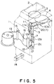
- Fig. 5 shows a coin wrapping machine, i.e., an example of a coin handling machine, to which the present invention is applied.
- the coin wrapping machine has a frame 1 having a coin hopper 2 with an open upper end for receiving coins, and.
- a rotary disk 3 for receiving coins loaded through the coin hopper 2 is disposed in the frame 1.
- a coin carrying device 6' is disposed adjacent to the rotary disk 3.
- the coin carrying device 6' has a carrying passage 7 extending between an entrance to an exit to guide a plurality of coins in a single diametrical row from the entrance to the exit, and a rotary disk 4 for feeding coins one by one to the entrance of the carrying passage 7.
- the rotary disk 3 feeds coins to the rotary disk 4.
- An accumulating unit 5 is disposed at the exit of the carrying passage 7 to accumulate coins delivered thereto in a vertical stack.
- a carrying belt 8 is extended over a central part of the carrying passage 7.
- a coin counter not shown, that counts coins passed by the coin counter and a stopper 9 capable of being advanced into and retracted from the carrying passage 7 are disposed in a downstream section of the carrying passage 7. Every time a predetermined number of coins pass the coin counter, i.e., every time a predetermined number of coins are accumulated in the accumulating unit 5, the stopper 9 is advanced into the carrying passage 7 to restrain coins in the carrying passage 7 forcibly from being carried.
- a wrapping unit 12 is disposed below the coin accumulating unit 5.
- the wrapping unit 12 receives a stack of coins C from the coin accumulating unit 5 and wraps the coins C in wrapping paper 13.
- a coin package thus formed by wrapping coins C by the wrapping unit 12 is discharged through a discharge opening 14 formed in a lower part of the frame 1.
- the present invention provides a coin carrying device comprising: a carrying structure defining a carrying passage along which coins are carried in a diametrical row, having an entrance and an exit; a coin feed mechanism for feeding coins one by one to the entrance of the carrying passage; a carrying mechanism for carrying the coins fed to the carrying structure from the entrance to the exit along the carrying passage; a stopping member disposed near the exit of the carrying passage so as to be advanced into and retracted from the carrying passage and capable of forcibly stopping the advancement of the coins when advanced into the carrying passage; a coin separating member having a contact part capable of being laterally advanced into and retracted from the carrying passage at a position downstream from the second coin from the head coin stopped in the carrying passage by the stopping member; and a biasing member for biasing the contact part of the coin separating member toward the carrying passage; wherein the contact part of the coin separating member advanced into the carrying passage is pressed against a periphery of the coin being carried, the contact part is urged away from the carrying passage
- the successive coins can be forcibly separated from each other near the exit of the carrying passage by the biasing force of the biasing member exerted through the contact part of the coin separating member on the preceding one of the adjacent coins. Consequently, the coins linked with each other or arranged in contact with each other when the advancement of the row of coins is stopped forcibly by the stopping member can be separated from each other before reaching the exit of the carrying passage. Therefore, circumferentially grooved coins, not to mention ordinary coins, can be separated from each other and can be properly carried.
- the coin carrying device further comprises a retaining mechanism capable of retaining the coin separating member with the contact part thereof retracted from the carrying passage.
- the retaining mechanism When carrying coins other than circumferentially grooved coins, the retaining mechanism retains the coin separating member with the contact part thereof retracted from the carrying passage to prevent the coin separating member from useless actions.
- the width of the carrying passage can be adjusted to a value corresponding to a diameter of coins to be carried along the carrying passage
- the coin carrying device further comprises an interlocking mechanism interlocking the carrying structure with the coin separating member and capable of automatically retaining the coin separating member with the contact part thereof retracted from the carrying passage when the width of the carrying passage is adjusted.
- the coin separating member can be automatically retained in a retracted state by the interlocking mechanism. Therefore, any special operation and any independent driving means for operating the retaining mechanism are unnecessary, operability is improved, and the use of the interlocking mechanism is advantageous in cost.
- the contact part of the coin separating member may be a roller.
- the roller serving as the contact part enables smooth operation of the coin separating member.
- the coin separating member may be a lever having one end provided with the contact part.
- the biasing member may be a spring connected to the other end of the lever serving as the coin separating member.
- a coin carrying device in a preferred embodiment according to the present invention will be described as applied to the coin wrapping machine shown in Fig. 5.
- the coin wrapping machine has the frame 1 having the coin hopper 2 with the open upper end for receiving coins, and.
- the rotary disk 3 for receiving coins loaded through the coin hopper 2 is disposed in the frame 1.
- a coin carrying device 6 embodying the present invention is disposed adjacent to the rotary disk 3.
- the coin carrying device 6 has a carrying passage 20 extending between an entrance to an exit to guide a plurality of coins in a single diametrical row from the entrance to the exit, and a rotary disk 4 for feeding coins one by one to the entrance of the carrying passage 20 (Fig. 1).
- the rotary disk 3 feeds coins to the rotary disk 4.
- the carrying passage 20 extends substantially tangentially to the rotary disk 4.
- the width L of the carrying passage 20 can be adjusted to a value corresponding to the diameter of coins to be carried along the carrying passage 20.
- An accumulating unit 5 is disposed at the exit of the carrying passage 20 to accumulate coins delivered thereto in a vertical stack.
- Coins fed by the rotary disk 4 to the carrying passage 20 are carried by a carrying mechanism similar to that shown in Figs. 6A and 6B along the carrying passage 20.
- the carrying mechanism includes a carrying a belt 8 extended above a central part of the carrying passage 20 as shown in Fig. 1.
- the carrying belt 8 is pressed against coins from above to carry the coins.
- 'upstream side' signifies an upstream side with respect to a coin carrying direction or a side on the side of the entrance of the carrying passage 20
- 'downstream side' signifies a downstream side with respect to the coin carrying direction or a side on the side of the exit of the carrying passage 20.
- Coins C are carried in a single diametrical, row in a horizontal position along the carrying passage 20.
- a coin counter S 1 counts the coins C that passes by the same.
- the counted coins C are discharged through the exit.
- the coins C similarly to those shown in Figs. 6A and 6B, collides against a stopping wall 10 of the coin accumulating unit 5 and drop into a space between a pair of vertical belts 11.
- the coins C dropped into the space between the pair of vertical belts 11 are accumulated in a vertical stack on projections 11a projecting from the opposite surfaces of the vertical belts 11.
- a wrapping unit 12 is disposed below the coin accumulating unit 5.
- the wrapping unit 12 receives stacked coins from the coin accumulating unit 5, and wraps the stacked coins in wrapping paper 13 by three wrapping rollers 12a, 12b and 12c.
- a coin package thus famed by the wrapping unit 12 is discharged through a discharge opening 14 famed in a lower part of the frame 1.
- indicated at 15 is a wrapping paper feed roller
- at 16 is a wrapping paper cutter
- at 17 are crimping needles for crimping upper and lower end parts of the wrapping paper wrapped around the coin stack.
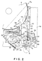
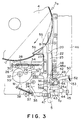
- Figs. 1 to 3 show the coin carrying device 6 set in different conformations differing from each other in the width L (Fig. 1) of the carrying passage 20, respectively.
- the carrying passage 20 of the coin carrying device 6 is set in a width for carrying the circumferentially grooved coin C a shown in Fig. 7A, in a maximum width and in a minimum width, respectively
- the carrying passage 20 is defined by a fixed guide member 22 and a movable guide member 23 disposed opposite to the fixed guide member 22.
- An entrance bottom plate 21 is disposed in a plane substantially the same as that including the rotary disk 4 at a position on the side of the entrance of the carrying passage 20.
- An exit bottom plate 24 is disposed at a position on the side of the exit of the carrying passage 20.
- a small-diameter coin eliminating opening 25 is defined by the fixed guide member 22, the movable guide member 23, the entrance bottom plate 21 and the exit bottom plate 24.
- the movable guide member 23 has a straight guide part 23a provided with a step 23b for supporting coins thereon, and a leg part 26 horizontally extending from the back of the straight guide part 23a.
- the leg part 26 is provided with slots 27 and 28 extending in a direction perpendicular to the straight guide part 23a.
- Guide rollers 29 and 30 supported on the frame 1 is fitted in the slots 27 and 28, respectively, to support the movable guide member 23 for linear movement toward and away from the fixed guide member 22.
- a cam follower 31, i.e., a roller, is supported on the leg part 26.
- the movable guide member 23 is biased away from the fixed guide member 22 by a spring 34 so that the cam follower 31 is always in engagement with the cam surface of a stepless cam 33 supported for turning by a shaft 32 on the frame 1.
- the stepless cam 33 has a spiral cam surface between a minimum stroke point 33a and a maximum stroke point 33b. Effective radius of the stepless cam 33 increases gradually from the minimum stroke point 33a toward the maximum stroke point 33b. A recess is formed in the periphery of the stepless cam 33 in a section near the minimum stroke point 33a.
- the movable guide member 23 is disposed to form the carrying passage 20 in the maximum width when the cam follower 31 is in contact with the minimum stroke point 33a of the stepless cam 33 as shown in Fig. 2.
- the position of the stepless cam 33 in this state is an original position.
- the stepless cam 33 can be turned through a predetermined angle by a pulse motor M.
- a substantially L-shaped auxiliary guide member 35 has one end pivotally joined by a joining pin 36 to a downstream end part of the movable guide member 23.
- the auxiliary guide member 35 is biased by a spring 38 so that the other end thereof is in contact with a guide member 37 fixed to the frame 1.
- the angle of a guide surface 35a of the auxiliary guide member 35 changes when the position of the movable guide member 23 is changed.
- the guide surface 35a of the auxiliary guide member 35 is turned relative to the straight guide part 23a of the movable guide member 23 toward the fixed guide member 22 as shown in Fig. 2 when the width of the carrying passage 20 is increased.
- the guide surface 35a of the auxiliary guide member 35 is turned relative to the straight guide part 23a of the movable guide member 23 away from the fixed guide member 22 toward a position where the guide surface 35a is aligned with the straight guide part 23a of the movable guide member 23 when the width of the carrying passage 20 is reduced. Consequently, an exit section of the carrying passage 20 is directed toward the center of the coin accumulating unit 5 regardless of the width of the carrying passage 20, and the free end of the guide surface 35a of the auxiliary guide member 35 approaches the coin accumulating unit 5 as the width of the carrying passage 20 is reduced to a width suitable for carrying small-diameter coins.
- the exit bottom plate 24 has an end part on the side of the movable guide member 23 pivotally supported by a shaft 39 on the frame 1.
- a pin 40 projecting from the exit bottom plate 24 is fitted in a slot 42 formed in a projection 41 of the movable guide member 23 projecting toward the carrying passage 20.
- the coin counter S 1 and a coin sensor S 2 capable of sensing a coin that passed by the coin sensor S 2 are supported side by side on a free end part of the exit bottom plate 24.
- the exit bottom plate 24 is turned so that the respective axes of the coin counter S 1 and the coin sensor S 2 are always substantially perpendicular to the guide surface 35a of the auxiliary guide member 35.
- the stopping member 43 is advanced into the carrying passage 20 to stop the following coins forcibly on the carrying passage 20.
- An arm 44 supporting a bottom plate support roller 45 is projected from the free end part of the exit bottom plate 24.
- the roller 45 rolls on a flat plate 46 attached to the frame 1 to support the free end part of the exit bottom plate 24.
- Guide rollers 47 are supported on a downstream end part of the exit bottom plate 24 to support a coin thereon.
- a vertical side guide plate 48 is formed integrally with a downstream part of the fixed guide member 22 so as to extend over the upper surface of the exit bottom plate 24.
- a gap smaller than the thickness of coins having the smallest thickness among the coins to be handled is formed between the side guide plate 48 and the upper surface of the exit bottom plate 24.
- a coin separating lever 50 is supported pivotally for a swing motion by a shaft 49 on a free end part of the exit bottom plate 24 at a position near a downstream end part 48a of the side guide plate 48.
- a small-diameter roller (contact part)51 is supported pivotally on a first end of the coin separating lever 50 on the side of the carrying passage 20.
- An extension spring 52 is extended between a second end part of the coin separating lever 50 and the flat plate 46 to bias the coin separating lever 50 clockwise.
- the clockwise turning of the coin separating lever 50 is limited by a stopper 53 attached to the flat plate 46.
- a hole 54 is formed in the coin separating lever 50 at a position near the shaft 49.
- a lower part of a pin inserted in the hole 54 come into contact with a stepped part 24a (Fig. 3) formed in a free end of the exit bottom plate 24 to restrain the coin separating lever 50 from clockwise turning.
- the pin and the exit bottom plate 24 constitute a retaining mechanism for retaining the coin separating lever 50 at an inoperative position with the roller 51 retracted from the carrying passage 20.
- the coin separating lever 50 may be retained at the inoperative position by other retaining means, such as a retaining means including a locking member for retaining the coin separating lever 50 at the inoperative position and a solenoid for operating the locking member.
- the coin carrying device is provided with an interlocking mechanism capable of retaining the coin separating lever 50 with the roller 51 retracted from the carrying passage 20 when the movable guide member 23 is moved for passage width adjustment.
- the interlocking mechanism includes the stepless cam 33 for passage width adjustment, the movable guide member 23, the exit bottom plate 24, the side guide plate 48 of the fixed guide member 22 and the stopper 53. Due to the interlocking mechanism, the roller 51 is advanced into the carrying passage 20 only when carrying the circumferentially grooved coins C a , and is retracted from the carrying passage 20 when carrying coins other than the circumferentially grooved coins C a .
- the interlocking mechanism includes the stepless cam 33 for passage width adjustment, the movable guide member 23, the exit bottom plate 24, the side guide plate 48 of the fixed guide member 22 and the stopper 53. Due to the interlocking mechanism, the roller 51 is advanced into the carrying passage 20 only when carrying the circumferentially grooved coins C a , and is retracted from the carrying passage 20 when carrying coins other than
- a level sensor for detecting level and the presence of coins on the rotary disk 4
- at 55 is a thickness limiting member to prevent feeding two superposed coins at a time to the carrying passage 20
- at 56 is a guide plate for guiding coins moving on the rotary disk 4 backward with respect to the rotating direction of the rotary disk 4 to prevent coins from piling up on the rotary disk 4.
- a gap greater than the thickness of each of coins to be carried and smaller than twice the thickness of the coin is formed between the thickness limiting member 55 and the upper surface of the rotary disk 4.
- the guide plate 56 attached to the movable guide member 23 so as to overlie the rotary disk 4.
- the width of the carrying passage 20 is adjusted by moving the movable guide member 23 from the original position corresponding to the maximum width shown in Fig. 2 toward the fixed guide member 22 by turning the stepless cam 33 through a predetermined angle by the pulse motor M.
- the movable guide member 23 In a state shown in Fig. 2 where the carrying passage has the maximum width, the movable guide member 23 is at the leftmost position. Since the joining pin 36 joining the auxiliary guide member 35 to the downstream end part of the movable guide member 23 is at the leftmost position in this state, the guide surface 35a of the auxiliary guide member 35 is turned on the joint pin 36 toward the coin accumulating unit 5 at a maximum inclination.
- the pin 40 is forced to move along the slot 42, so that the exit bottom plate 24 is turned counterclockwise on the shaft 39, the respective axes of the coin counter S 1 and the coin sensor S 2 remain substantially perpendicular to the guide surface 35a of the auxiliary guide member 35, and the center line of the section of the carrying passage 20 corresponding to the coin counter S 1 and the coin sensor S 2 passes the center of the coin accumulating unit 5.
- the coin separating lever 50 is shifted upward as viewed in Fig. 2 when the exit bottom plate 24 is turned counterclockwise.
- the roller 51 supported on the coin separating lever 50 is pushed by the back surface of the downstream end part 48a of the side guide plate 48 opposite the surface of the same facing the carrying passage 20, so that the coin separating lever 50 is turned counterclockwise on the shaft 49 against the resilience of the spring 52. Therefore, when the movable guide member 23 is at the leftmost position corresponding to the maximum width of the carrying passage 20, the roller 51 is in contact with the back surface of the downstream end part 48a of the side guide plate 48 and kept retracted from the carrying passage 20.
- a predetermined number of driving pulses are given to the pulse motor M to turn the stepless cam 33 clockwise, as viewed in Fig. 2, to move the movable guide member 23 from the original position shown in Fig. 2 toward the fixed guide member 22 so that the width of the carrying passage 20 is adjusted to a value corresponding to the diameter of the coins.
- the second end part of the coin separating lever 50 comes into contact with the stopper 53 and the roller 51 is held at the retracted position outside the carrying passage 20, i.e., on the outer side of the extension of the side guide plate 48. Therefore, the coins can be carried along the carrying passage 20 without being obstructed by the roller 51.
- a predetermined number of driving pulses are given to the pulse motor M to turn the stepless cam 33 through a predetermined angle to set the carrying passage 20 in a width corresponding to the diameter of the circumferentially grooved coins C a as shown in Fig. 1.
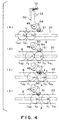
- Fig. 4 shows two circumferentially grooved coins C a1 and C a2 being carried along the carrying passage 20 by the carrying belt 8 at different positions during different phases (A)-(D) of a coin carrying operation.
- a vector a of a force exerted by the roller 51 on the preceding coin C a1 has a component b of a force that urges the preceding coin C a1 in the carrying direction.
- the force represented by the vector b is exerted on the preceding coin C a1 in addition to a carrying force exerted on the same by the carrying belt 8.
- the succeeding coin C a2 comes into contact with the roller 51 as sown in Fig. 4-(D). Then, the speed of the succeeding coin C a2 is reduced from V 1 to V 2 and the interval P between the coins C a1 and C a2 is increased.
- the preceding coin C a1 Since the preceding coin C a1 is spaced from the succeeding coin C a2 before the preceding coin C a1 reaches the exit of the carrying passage 20, parts of the peripheries of the adjacent coins C a1 and C a2 are not meshed into the circumferential grooves of the coins C a1 and C a2, and the coins C a1 and C a2 are not linked with each other as shown in Fig. 7B. Thus, the preceding coin C a1 can smoothly drop into the coin accumulating unit 5. Thus, all the circumferentially grooved coins C a can be successively separated from the succeeding coins and the circumferentially grooved coins C a can be smoothly accumulated in the coin accumulating unit 5.
- the pin When handling coins other than the circumferentially grooved coins C a , the pin is inserted in the hole 54 of the coin separating lever 50.
- the pin rests on the stepped part 24a of the exit bottom plate 24 and thereby the roller 51 of the coin separating lever 50 can be retained at the inoperative position regardless of the adjustment of the width of the carrying passage 20.
- the coin separating lever 50 It is desirable in view of efficiency to eliminate work for setting the coin separating lever 50 at the operative position when handling circumferentially grooved coins and for retaining the same at the inoperative position when handling coins other than circumferentially grooved coins by designing the coin carrying device so that the coin separating lever 50 is set automatically at the operative position or is retained automatically at the inoperative position by the operation for adjusting the width of the carrying passage.
- the coin separating lever 50 may be set manually at the operative position only when necessary or may be manually retracted to the inoperative position.
- the present invention is not limited in its application to the carriage of the coins, but can be applied to the carriage of medals or the like.
Landscapes
- Physics & Mathematics (AREA)
- General Physics & Mathematics (AREA)
- Basic Packing Technique (AREA)
- Attitude Control For Articles On Conveyors (AREA)
- Medicinal Preparation (AREA)
- Refuse Collection And Transfer (AREA)
Abstract
Description
Claims (6)
- A coin carrying device comprising:a carrying structure defining a carrying passage along which coins are carried in a diametrical row, having an entrance and an exit;a coin feed mechanism for feeding coins one by one to the entrance of the carrying passage;a carrying mechanism for carrying the coins fed to the carrying structure from the entrance to the exit along the carrying passage;a stopping member disposed near the exit of the carrying passage so as to be advanced into and retracted from the carrying passage and capable of forcibly stopping the advancement of the coins when advanced into the carrying passage;a coin separating member having a contact part capable of being laterally advanced into and retracted from the carrying passage at a position downstream from the second coin from the head coin stopped in the carrying passage by the stopping member; anda biasing member for biasing the contact part of the coin separating member toward the carrying passage;
wherein the contact part of the coin separating member advanced into the carrying passage is pressed against a periphery of the coin being carried, the contact part is urged away from the carrying passage by the coin passing the contact part against biasing force of the biasing member, and the contact part is advanced again by the biasing member into the carrying passage after the coin has passed the contact part. - The coin carrying device according to claim 1, further comprising a retaining mechanism capable of retaining the coin separating member with the contact part thereof retracted from the carrying passage.
- The coin carrying device according to claim 2, wherein width of the carrying passage can be adjusted to a value corresponding to a diameter of coins to be carried along the carrying passage, andthe coin carrying device further comprises an interlocking mechanism interlocking the carrying structure with the coin separating member and capable of automatically retaining the coin separating member with the contact part thereof retracted from the carrying passage when the width of the carrying passage is adjusted.
- The coin carrying device according to claim 1, wherein the contact part of the coin separating member is a roller.
- The coin carrying device according to claim 1 or 4, wherein the coin separating member is a lever having one end provided with the contact part.
- The coin carrying device according to claim 5, wherein the biasing member is a spring connected to the other end of the lever serving as the coin separating member.
Applications Claiming Priority (2)
| Application Number | Priority Date | Filing Date | Title |
|---|---|---|---|
| JP12263199 | 1999-04-28 | ||
| JP12263199A JP3821983B2 (en) | 1999-04-28 | 1999-04-28 | Coin handling passage device for coin handling machine |
Publications (3)
| Publication Number | Publication Date |
|---|---|
| EP1049053A2 true EP1049053A2 (en) | 2000-11-02 |
| EP1049053A3 EP1049053A3 (en) | 2003-10-15 |
| EP1049053B1 EP1049053B1 (en) | 2007-01-24 |
Family
ID=14840761
Family Applications (1)
| Application Number | Title | Priority Date | Filing Date |
|---|---|---|---|
| EP00303485A Expired - Lifetime EP1049053B1 (en) | 1999-04-28 | 2000-04-26 | Coin carrying device |
Country Status (6)
| Country | Link |
|---|---|
| US (1) | US6350192B1 (en) |
| EP (1) | EP1049053B1 (en) |
| JP (1) | JP3821983B2 (en) |
| AT (1) | ATE352828T1 (en) |
| DE (1) | DE60033078T2 (en) |
| ES (1) | ES2279747T3 (en) |
Families Citing this family (4)
| Publication number | Priority date | Publication date | Assignee | Title |
|---|---|---|---|---|
| US6499277B1 (en) | 2000-02-22 | 2002-12-31 | Cummins-Allison Corp. | Coin wrapper |
| JP4810691B2 (en) * | 2003-12-12 | 2011-11-09 | 旭精工株式会社 | Coin hopper |
| US8172654B2 (en) * | 2007-04-16 | 2012-05-08 | String Gregory F | Coin processing machine with pivoting alignment finger |
| CN110853215B (en) * | 2019-11-19 | 2021-09-10 | 广州市鸿恒电子科技有限公司 | Upper coin-out type coin counter |
Family Cites Families (10)
| Publication number | Priority date | Publication date | Assignee | Title |
|---|---|---|---|---|
| US824842A (en) * | 1905-10-30 | 1906-07-03 | Brandt Cashier Company | Coin-holder. |
| US1113920A (en) * | 1914-06-27 | 1914-10-13 | Jesse C Waugh | Coin-holder. |
| US1615642A (en) * | 1925-04-21 | 1927-01-25 | John C Martine | Coin holder |
| US4592377A (en) * | 1984-07-02 | 1986-06-03 | Igt | Coin escalator |
| JPS63314868A (en) * | 1987-10-03 | 1988-12-22 | Nec Corp | Manufacture of mos semiconductor device |
| US4923430A (en) * | 1987-10-14 | 1990-05-08 | Kabushiki Kaisha Sigma | Coin payout apparatus in gaming device |
| US5484334A (en) * | 1994-04-01 | 1996-01-16 | Evdokimo; Allen J. | Coin handling apparatus with coin filter and improved coin interlock |
| TW304608U (en) * | 1995-02-23 | 1997-05-01 | Asahi Seiko Co Ltd | Coin conveying device |
| GB9523405D0 (en) * | 1995-11-16 | 1996-01-17 | Coin Controls | Coin dispensing mechanism |
| US5876275A (en) * | 1997-01-30 | 1999-03-02 | Wms Gaming Inc. | Escalator with adjustable coin guides |
-
1999
- 1999-04-28 JP JP12263199A patent/JP3821983B2/en not_active Expired - Fee Related
-
2000
- 2000-04-26 EP EP00303485A patent/EP1049053B1/en not_active Expired - Lifetime
- 2000-04-26 DE DE60033078T patent/DE60033078T2/en not_active Expired - Lifetime
- 2000-04-26 AT AT00303485T patent/ATE352828T1/en not_active IP Right Cessation
- 2000-04-26 ES ES00303485T patent/ES2279747T3/en not_active Expired - Lifetime
- 2000-04-27 US US09/560,282 patent/US6350192B1/en not_active Expired - Fee Related
Also Published As
| Publication number | Publication date |
|---|---|
| JP3821983B2 (en) | 2006-09-13 |
| EP1049053B1 (en) | 2007-01-24 |
| DE60033078D1 (en) | 2007-03-15 |
| JP2000311271A (en) | 2000-11-07 |
| ES2279747T3 (en) | 2007-09-01 |
| ATE352828T1 (en) | 2007-02-15 |
| US6350192B1 (en) | 2002-02-26 |
| DE60033078T2 (en) | 2007-06-14 |
| EP1049053A3 (en) | 2003-10-15 |
Similar Documents
| Publication | Publication Date | Title |
|---|---|---|
| US4997406A (en) | Coin removing apparatus for coin handling machine | |
| KR100918582B1 (en) | Paper sheet delivery mechanism | |
| US8961276B2 (en) | Coin feeding device | |
| JP5969264B2 (en) | Banknote recirculation device | |
| EP0893786A1 (en) | Coin wrapping machine | |
| US6350192B1 (en) | Coin carrying device | |
| US8961275B2 (en) | Coin depositing and dispensing machine | |
| US20020112455A1 (en) | Coin stacker | |
| US4409773A (en) | Coin wrapping machine | |
| JP2679382B2 (en) | Belt type coin dispenser | |
| US4362176A (en) | Device for adjusting coin passage of coin handling machine | |
| US4993990A (en) | Unacceptable coin removing apparatus for coin handling machine | |
| EP2325088B1 (en) | Coin wrapping machine | |
| US7775863B2 (en) | Coin dispending device and method for rapidly recycling coins | |
| JP3857860B2 (en) | Coin stacking and dispensing device | |
| GB2213472A (en) | Sheet feeding apparatus | |
| JPH082763Y2 (en) | Coin sorting passage device | |
| JP3723059B2 (en) | Rotary solenoid drive transmission mechanism and coin processor using the same | |
| US11989995B2 (en) | Coin feeding device | |
| US7470175B2 (en) | Coin stacking apparatus | |
| JP3880671B2 (en) | Bill feeding device | |
| JPH03218596A (en) | Coin returning device for automatic vending machine | |
| JP7428624B2 (en) | Coin sorting device, coin processing device and coin sorting method | |
| JP5108464B2 (en) | Coin processing equipment | |
| JP4644773B2 (en) | Disk sorting device |
Legal Events
| Date | Code | Title | Description |
|---|---|---|---|
| PUAI | Public reference made under article 153(3) epc to a published international application that has entered the european phase |
Free format text: ORIGINAL CODE: 0009012 |
|
| AK | Designated contracting states |
Kind code of ref document: A2 Designated state(s): AT BE CH CY DE DK ES FI FR GB GR IE IT LI LU MC NL PT SE |
|
| AX | Request for extension of the european patent |
Free format text: AL;LT;LV;MK;RO;SI |
|
| PUAL | Search report despatched |
Free format text: ORIGINAL CODE: 0009013 |
|
| AK | Designated contracting states |
Kind code of ref document: A3 Designated state(s): AT BE CH CY DE DK ES FI FR GB GR IE IT LI LU MC NL PT SE |
|
| AX | Request for extension of the european patent |
Extension state: AL LT LV MK RO SI |
|
| RIC1 | Information provided on ipc code assigned before grant |
Ipc: 7G 07D 3/12 A Ipc: 7G 07D 1/00 B |
|
| 17P | Request for examination filed |
Effective date: 20040210 |
|
| AKX | Designation fees paid |
Designated state(s): AT BE CH CY DE DK ES FI FR GB GR IE IT LI LU MC NL PT SE |
|
| 17Q | First examination report despatched |
Effective date: 20041110 |
|
| GRAP | Despatch of communication of intention to grant a patent |
Free format text: ORIGINAL CODE: EPIDOSNIGR1 |
|
| GRAS | Grant fee paid |
Free format text: ORIGINAL CODE: EPIDOSNIGR3 |
|
| GRAA | (expected) grant |
Free format text: ORIGINAL CODE: 0009210 |
|
| AK | Designated contracting states |
Kind code of ref document: B1 Designated state(s): AT BE CH CY DE DK ES FI FR GB GR IE IT LI LU MC NL PT SE |
|
| PG25 | Lapsed in a contracting state [announced via postgrant information from national office to epo] |
Ref country code: LI Free format text: LAPSE BECAUSE OF FAILURE TO SUBMIT A TRANSLATION OF THE DESCRIPTION OR TO PAY THE FEE WITHIN THE PRESCRIBED TIME-LIMIT Effective date: 20070124 Ref country code: FI Free format text: LAPSE BECAUSE OF FAILURE TO SUBMIT A TRANSLATION OF THE DESCRIPTION OR TO PAY THE FEE WITHIN THE PRESCRIBED TIME-LIMIT Effective date: 20070124 Ref country code: AT Free format text: LAPSE BECAUSE OF FAILURE TO SUBMIT A TRANSLATION OF THE DESCRIPTION OR TO PAY THE FEE WITHIN THE PRESCRIBED TIME-LIMIT Effective date: 20070124 Ref country code: DK Free format text: LAPSE BECAUSE OF FAILURE TO SUBMIT A TRANSLATION OF THE DESCRIPTION OR TO PAY THE FEE WITHIN THE PRESCRIBED TIME-LIMIT Effective date: 20070124 Ref country code: NL Free format text: LAPSE BECAUSE OF FAILURE TO SUBMIT A TRANSLATION OF THE DESCRIPTION OR TO PAY THE FEE WITHIN THE PRESCRIBED TIME-LIMIT Effective date: 20070124 Ref country code: CH Free format text: LAPSE BECAUSE OF FAILURE TO SUBMIT A TRANSLATION OF THE DESCRIPTION OR TO PAY THE FEE WITHIN THE PRESCRIBED TIME-LIMIT Effective date: 20070124 |
|
| REG | Reference to a national code |
Ref country code: GB Ref legal event code: FG4D |
|
| REG | Reference to a national code |
Ref country code: CH Ref legal event code: EP |
|
| RAP2 | Party data changed (patent owner data changed or rights of a patent transferred) |
Owner name: GLORY LTD. |
|
| REG | Reference to a national code |
Ref country code: IE Ref legal event code: FG4D |
|
| REF | Corresponds to: |
Ref document number: 60033078 Country of ref document: DE Date of ref document: 20070315 Kind code of ref document: P |
|
| REG | Reference to a national code |
Ref country code: SE Ref legal event code: TRGR |
|
| NLT2 | Nl: modifications (of names), taken from the european patent patent bulletin |
Owner name: GLORY LTD. Effective date: 20070221 |
|
| PG25 | Lapsed in a contracting state [announced via postgrant information from national office to epo] |
Ref country code: PT Free format text: LAPSE BECAUSE OF FAILURE TO SUBMIT A TRANSLATION OF THE DESCRIPTION OR TO PAY THE FEE WITHIN THE PRESCRIBED TIME-LIMIT Effective date: 20070625 |
|
| REG | Reference to a national code |
Ref country code: CH Ref legal event code: PL |
|
| NLV1 | Nl: lapsed or annulled due to failure to fulfill the requirements of art. 29p and 29m of the patents act | ||
| ET | Fr: translation filed | ||
| REG | Reference to a national code |
Ref country code: ES Ref legal event code: FG2A Ref document number: 2279747 Country of ref document: ES Kind code of ref document: T3 |
|
| PLBE | No opposition filed within time limit |
Free format text: ORIGINAL CODE: 0009261 |
|
| STAA | Information on the status of an ep patent application or granted ep patent |
Free format text: STATUS: NO OPPOSITION FILED WITHIN TIME LIMIT |
|
| GBPC | Gb: european patent ceased through non-payment of renewal fee |
Effective date: 20070426 |
|
| 26N | No opposition filed |
Effective date: 20071025 |
|
| PG25 | Lapsed in a contracting state [announced via postgrant information from national office to epo] |
Ref country code: BE Free format text: LAPSE BECAUSE OF FAILURE TO SUBMIT A TRANSLATION OF THE DESCRIPTION OR TO PAY THE FEE WITHIN THE PRESCRIBED TIME-LIMIT Effective date: 20070124 |
|
| PG25 | Lapsed in a contracting state [announced via postgrant information from national office to epo] |
Ref country code: GB Free format text: LAPSE BECAUSE OF NON-PAYMENT OF DUE FEES Effective date: 20070426 Ref country code: GR Free format text: LAPSE BECAUSE OF FAILURE TO SUBMIT A TRANSLATION OF THE DESCRIPTION OR TO PAY THE FEE WITHIN THE PRESCRIBED TIME-LIMIT Effective date: 20070425 |
|
| PG25 | Lapsed in a contracting state [announced via postgrant information from national office to epo] |
Ref country code: IE Free format text: LAPSE BECAUSE OF NON-PAYMENT OF DUE FEES Effective date: 20070426 |
|
| PG25 | Lapsed in a contracting state [announced via postgrant information from national office to epo] |
Ref country code: MC Free format text: LAPSE BECAUSE OF NON-PAYMENT OF DUE FEES Effective date: 20070430 |
|
| PG25 | Lapsed in a contracting state [announced via postgrant information from national office to epo] |
Ref country code: CY Free format text: LAPSE BECAUSE OF FAILURE TO SUBMIT A TRANSLATION OF THE DESCRIPTION OR TO PAY THE FEE WITHIN THE PRESCRIBED TIME-LIMIT Effective date: 20070124 |
|
| PG25 | Lapsed in a contracting state [announced via postgrant information from national office to epo] |
Ref country code: LU Free format text: LAPSE BECAUSE OF NON-PAYMENT OF DUE FEES Effective date: 20070426 |
|
| PGFP | Annual fee paid to national office [announced via postgrant information from national office to epo] |
Ref country code: ES Payment date: 20110427 Year of fee payment: 12 Ref country code: FR Payment date: 20110426 Year of fee payment: 12 |
|
| PGFP | Annual fee paid to national office [announced via postgrant information from national office to epo] |
Ref country code: IT Payment date: 20110422 Year of fee payment: 12 |
|
| REG | Reference to a national code |
Ref country code: FR Ref legal event code: ST Effective date: 20121228 |
|
| PG25 | Lapsed in a contracting state [announced via postgrant information from national office to epo] |
Ref country code: FR Free format text: LAPSE BECAUSE OF NON-PAYMENT OF DUE FEES Effective date: 20120430 Ref country code: IT Free format text: LAPSE BECAUSE OF NON-PAYMENT OF DUE FEES Effective date: 20120426 |
|
| REG | Reference to a national code |
Ref country code: ES Ref legal event code: FD2A Effective date: 20130716 |
|
| PG25 | Lapsed in a contracting state [announced via postgrant information from national office to epo] |
Ref country code: ES Free format text: LAPSE BECAUSE OF NON-PAYMENT OF DUE FEES Effective date: 20120427 |
|
| PGFP | Annual fee paid to national office [announced via postgrant information from national office to epo] |
Ref country code: SE Payment date: 20140418 Year of fee payment: 15 |
|
| REG | Reference to a national code |
Ref country code: SE Ref legal event code: EUG |
|
| PG25 | Lapsed in a contracting state [announced via postgrant information from national office to epo] |
Ref country code: SE Free format text: LAPSE BECAUSE OF NON-PAYMENT OF DUE FEES Effective date: 20150427 |
|
| PGFP | Annual fee paid to national office [announced via postgrant information from national office to epo] |
Ref country code: DE Payment date: 20160421 Year of fee payment: 17 |
|
| REG | Reference to a national code |
Ref country code: DE Ref legal event code: R119 Ref document number: 60033078 Country of ref document: DE |
|
| PG25 | Lapsed in a contracting state [announced via postgrant information from national office to epo] |
Ref country code: DE Free format text: LAPSE BECAUSE OF NON-PAYMENT OF DUE FEES Effective date: 20171103 |