EP1048995A2 - Method of displaying images with a touchpanel for a molded form-take out robot - Google Patents
Method of displaying images with a touchpanel for a molded form-take out robot Download PDFInfo
- Publication number
- EP1048995A2 EP1048995A2 EP00108975A EP00108975A EP1048995A2 EP 1048995 A2 EP1048995 A2 EP 1048995A2 EP 00108975 A EP00108975 A EP 00108975A EP 00108975 A EP00108975 A EP 00108975A EP 1048995 A2 EP1048995 A2 EP 1048995A2
- Authority
- EP
- European Patent Office
- Prior art keywords
- image
- display device
- operator
- sheet switch
- selecting
- Prior art date
- Legal status (The legal status is an assumption and is not a legal conclusion. Google has not performed a legal analysis and makes no representation as to the accuracy of the status listed.)
- Withdrawn
Links
Images



Classifications
-
- G—PHYSICS
- G05—CONTROLLING; REGULATING
- G05B—CONTROL OR REGULATING SYSTEMS IN GENERAL; FUNCTIONAL ELEMENTS OF SUCH SYSTEMS; MONITORING OR TESTING ARRANGEMENTS FOR SUCH SYSTEMS OR ELEMENTS
- G05B19/00—Program-control systems
- G05B19/02—Program-control systems electric
- G05B19/18—Numerical control [NC], i.e. automatically operating machines, in particular machine tools, e.g. in a manufacturing environment, so as to execute positioning, movement or co-ordinated operations by means of program data in numerical form
- G05B19/409—Numerical control [NC], i.e. automatically operating machines, in particular machine tools, e.g. in a manufacturing environment, so as to execute positioning, movement or co-ordinated operations by means of program data in numerical form characterised by using manual data input [MDI] or by using control panel, e.g. controlling functions with the panel; characterised by control panel details or by setting parameters
-
- B—PERFORMING OPERATIONS; TRANSPORTING
- B29—WORKING OF PLASTICS; WORKING OF SUBSTANCES IN A PLASTIC STATE IN GENERAL
- B29C—SHAPING OR JOINING OF PLASTICS; SHAPING OF MATERIAL IN A PLASTIC STATE, NOT OTHERWISE PROVIDED FOR; AFTER-TREATMENT OF THE SHAPED PRODUCTS, e.g. REPAIRING
- B29C45/00—Injection moulding, i.e. forcing the required volume of moulding material through a nozzle into a closed mould; Apparatus therefor
- B29C45/17—Component parts, details or accessories; Auxiliary operations
- B29C45/76—Measuring, controlling or regulating
- B29C45/7626—Measuring, controlling or regulating the ejection or removal of moulded articles
-
- B—PERFORMING OPERATIONS; TRANSPORTING
- B29—WORKING OF PLASTICS; WORKING OF SUBSTANCES IN A PLASTIC STATE IN GENERAL
- B29C—SHAPING OR JOINING OF PLASTICS; SHAPING OF MATERIAL IN A PLASTIC STATE, NOT OTHERWISE PROVIDED FOR; AFTER-TREATMENT OF THE SHAPED PRODUCTS, e.g. REPAIRING
- B29C45/00—Injection moulding, i.e. forcing the required volume of moulding material through a nozzle into a closed mould; Apparatus therefor
- B29C45/17—Component parts, details or accessories; Auxiliary operations
- B29C45/76—Measuring, controlling or regulating
- B29C2045/7606—Controlling or regulating the display unit
Definitions
- the present invention relates to a method of displaying images with a touchpanel for a molded form-take out robot.
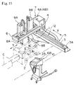
- a molded form-take out robot does, as shown in Fig. 11, comprise a first movement means 5, which is provided with a transverse beam 3 mounted and fixed at its root portion 1 directly onto a stationary platen 2A of an injection molding machine 2 and extending at a free end of the transverse beam 3 at a lateral side of the injection molding machine 2 as intersecting with a longitudinal axis C thereof, and also provided with, for example, a servo-motor 3A mounted on the transverse beam 3; a second movement means 7, which is provided with a drawing beam 6 (mounted on the transverse beam 3 with a root portion 4 being assembled on the same, extending along the longitudinal axis C of the injection molding machine 2, and movable, by actuation of the servo-motor 3A on the transverse beam 3, forwards and backwards in the extent from the root portion 1 to the free end of the same in the direction (indicated by the arrow X ) intersecting the longitudinal axis C ), and also provided with, for example, servo-motor
- the molded form-take out robot is subjected, before the start of automatic continuous operation, to such teaching operation with an image-display device 10 using a touchpanel that an operator performs an inputting operation (described later) to cause a liquid crystal panel 10A of the image-display device 10 to show an image of the molded form-take out robot, so that the operator does, while watching the shown image of the molded form-take out robot, set and input proper or suitable values for the amounts of strokes of the first movement means 5, of the second movement means 7 and of the raise and lower means 9A and 9B.
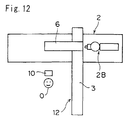
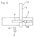
- the molded form-take out robot may be arranged with respect to the injection molding machine 2 in such separate patterns that the transverse beam 3 extends, as shown in Fig. 12, from a position on the injection molding machine 2 (where an injection part 2B mounted at the longitudinal rear side of the stationary platen 2A (see Fig. 11) is seen on the right-hand side) to a first lateral side of the machine 2 shown in Fig. 12, thereby causing the free end of the beam 3 to project outwards of the machine 2 ("Operator-side extension pattern 12"), or that the transverse beam 3 extends, as seen in Fig. 13, from the same position on the injection molding machine 2 (as above) to a second lateral side of the machine 2 shown in Fig. 13, with the free end of the beam 3 projecting outwards of the machine 2 oppositely to the first lateral side ("Opposite-side extension pattern 13").
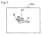
- the liquid crystal panel 10A of the image-display device 10 shows a three-dimensional image 23 of the take-out robot in the Operator-side extension pattern in which the transverse beam 3 extends in the first lateral side ("Operator side") as seen in Fig. 7.
- the conventional images-displaying method in which only the Operator-side robot image 23 can be shown on the liquid crystal panel 10A , in case that the molded form-take out robot is arranged in the Operator-side extension pattern 12 (Fig.
- the image-display device 10 is positioned at the Operator-side (i.e., at the first lateral side of the injection molding machine 2 with respect to the point thereon viewing the injection part 2B on the right-hand side), and when the operator does, while watching the three-dimensional image 23 of the Operator-side take out robot shown on the liquid crystal panel 10A , perform the foregoing "teaching" operation, the take out robot (set in the Operator-side extension pattern 12) and the three-dimensional image 23 (of the Operator-side take out robot shown on the liquid crystal panel 10A ) correspond in orientation to each other, thereby enabling the operator O to be prevented from misunderstanding the orientation, and also enabling avoiding an erroneous or incorrect teaching operation.
- the take out robot set in the Opposite-side extension pattern 13 as shown in Fig. 14 and the touchpanel type image-display device 10 is also positioned at the Opposite-side (i.e., in the second lateral side of the injection molding machine 2 with respect to the point thereon viewing the injection part 2B on the right-hand side), when the operator O does, while watching the three dimensional image 23 of the "Operator-side" take out robot shown on the liquid crystal panel 10A , perform the foregoing teaching operation, the take out robot (set in the Opposite-side extension pattern 13) and the three-dimensional image 23 (of the "Operator-side” take out robot shown on the liquid crystal panel 10A ) differ from each other in the orientation as that the drawing beams 6 extend reversely to each other, whereby operators' misunderstanding the orientation is very likely to happen, resulting in an incorrect teaching operation.
- the conventional images-displaying method using a touchpanel for the molded form-take out robot has no problems in the teaching operation by the operator watching the three-dimensional image of the Operator-side take out robot shown on the liquid crystal panel of the touchpanel type image-display device positioned at the Operator-side with the molded form-take out robot being arranged in the Operator-side extension pattern.
- the conventional method has a problem or fear of operators' misunderstanding the orientation and a resultant incorrect teaching operation due to difference in the orientation between the take out robot set in the Opposite-side extension pattern and the three dimensional image of the "Operator-side" take out robot shown on the liquid crystal panel when the operator does, while watching the three dimensional image of the "Operator-side” take out robot shown on the liquid crystal panel, perform the teaching operation in case that the molded form-take out robot is set in the Opposite-side extension pattern, and the touchpanel type image-display device is positioned at the Operator-side or at the Opposite-side.
- the present invention has been designed under the above circumstances.
- An object of the present invention is to provide a method of displaying images with a touchpanel for a molded form-take out robot wherein three-dimensional images of robot corresponding to the setting patterns of the molded form-take out robot and the set positions of the touchpanel type image-display device are shown, so that operators can perform the teaching operation without misunderstanding the orientation of the robot's images and the actual robot, thereby surely avoiding an incorrect teaching operation.
- the object of the present invention has been achieved by a method of displaying images with a touchpanel for a molded form-take out robot comprising a first movement means mounted and fixed at a root portion directly to an injection molding machine and moving forwards and backwards at least one grasping means in the widthwise direction of the injection molding machine intersecting the longitudinal direction thereof, and a second movement means moving forwards and backwards said at least one grasping means in the longitudinal direction of the injection molding machine, wherein there is provided a controller comprising a central processing unit, ROM having software programs, RAM storing data, and an input/output device provided with a touchpanel type image-display device and a sheet switch shown on the image-display device, so that in any of such three situations as a first situation in which the molded form-take out robot is set in an Operator-side extension pattern with the image-display device being positioned at the Operator-side; a second situation in which the robot is set in an Opposite-side extension pattern with the image-display device at the Operator-side
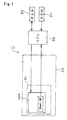
- FIG. 1 shows an example of the present invention in a block diagram.
- a controller 11 which makes controlling for using the present invention comprises a central processing unit (CPU) 30, a ROM 31 in which a software program is set, a RAM 32 storing data, and an input/output device 33 comprising an image-display device 10 using a touchpanel and a sheet switch shown as an image on a liquid crystal panel 10A of the image-display device 10.
- CPU central processing unit
- ROM 31 read-only memory
- RAM 32 random access memory
- an input/output device 33 comprising an image-display device 10 using a touchpanel and a sheet switch shown as an image on a liquid crystal panel 10A of the image-display device 10.
- the central processing unit 30 controls the input/output device 33 in accordance with the software program previously set in ROM 31.
- CPU 30 processes signals on the basis of switch signals, which are outputted by setting "ON” (called “touching” hereunder) the sheet switch shown on the liquid crystal panel 10A , and data stored in RAM 32, emits signals to the liquid crystal panel 10A to show thereon a predetermined image.
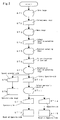
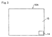
- the liquid crystal panel 10A of the image-display device 10 does, following start of operation in Fig. 2, show a main image 15 having a sheet switch 14 for selecting a menu image as seen in Fig. 3 (Step 1 in Fig. 2). Touching the sheet switch 14 (Step 2) causes the liquid crystal panel 10A to show a menu image 17 having a sheet switch 16 for selecting a function-selection image as seen in Fig. 4 (Step 3).
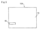
- Touching the sheet switch 16 causes the liquid crystal panel 10A to show a first function-selecting image 19 having a sheet switch 18 for selecting specific directions of taking molded forms as seen in Fig. 5 (Step 5).
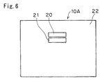
- Step 6 Touching the sheet switch 18 (Step 6) causes the liquid crystal panel 10A to show a second function-selecting image 22 having an Operator-side sheet switch 20 and an Opposite-side sheet switch 21 separately as seen in Fig. 6 (Step 7).
- Touching the Operator-side sheet switch 20 causes the liquid crystal panel 10A to show a three-dimensional image 23 of a molded-form take out robot set in the Operator-side in which the transverse beam 3 of the robot extends to the foregoing first lateral side of the injection molding machine (the Operator-side) as seen in Fig. 7 (Step 9).
- the liquid crystal panel 10A of the image-display device 10 does, following start of operation in Fig. 2, show a main image 15 having a sheet switch 14 for selecting a menu image as seen in Fig. 3 (Step 1 in Fig. 2). Touching the sheet switch 14 (Step 2) causes the liquid crystal panel 10A to show a menu image 17 having a sheet switch 16 for selecting a function-selection image as seen in Fig. 4 (Step 3).
- Touching the sheet switch 16 causes the liquid crystal panel 10A to show a first function-selecting image 19 having a sheet switch 18 for selecting specific directions of taking molded forms as seen in Fig. 5 (Step 5).
- Step 6 Touching the sheet switch 18 (Step 6) causes the liquid crystal panel 10A to show a second function-selecting image 22 having an Operator-side sheet switch 20 and an Opposite-side sheet switch 21 separately as seen in Fig. 6 (Step 7).
- Step 10 Touching the Opposite-side sheet switch 21 (Step 10) causes the liquid crystal panel 10A to show a third function-selecting image 26 having an Operator-side sheet switch 24 and an Opposite-side sheet switch 25 separately as seen in Fig. 8 (Step 11).
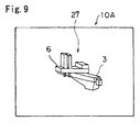
- Step 12 Touching the Operator-side sheet switch 24 (Step 12) causes the liquid crystal panel 10A to show a three-dimensional image 27 of a molded-form take out robot set in the Opposite-side in which the transverse beam 3 of the robot extends reversely, i.e., to the foregoing second lateral side of the injection molding machine (the Opposite-side) as seen in Fig. 9 (Step 13).
- the liquid crystal panel 10A of the image-display device 10 does, following start of operation in Fig. 2, show a main image 15 having a sheet switch 14 for selecting a menu image as seen in Fig. 3 (Step 1 in Fig. 2). Touching the sheet switch 14 (Step 2) causes the liquid crystal panel 10A to show a menu image 17 having a sheet switch 16 for selecting a function-selection image as seen in Fig. 4 (Step 3).
- Touching the sheet switch 16 causes the liquid crystal panel 10A to show a first function-selecting image 19 having a sheet switch 18 for selecting specific directions of taking molded forms as seen in Fig. 5 (Step 5).
- Step 6 Touching the sheet switch 18 (Step 6) causes the liquid crystal panel 10A to show a second function-selecting image 22 having an Operator-side sheet switch 20 and an Opposite-side sheet switch 21 separately as seen in Fig. 6 (Step 7).
- Step 10 Touching the Opposite-side sheet switch 21 (Step 10) causes the liquid crystal panel 10A to show a third function-selecting image 26 having an Operator-side sheet switch 24 and an Opposite-side sheet switch 25 separately as seen in Fig. 8 (Step 11).
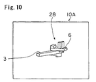
- Step 14 Touching the Opposite-side sheet switch 26 (Step 14) causes the liquid crystal panel 10A to show a three-dimensional image 28 of a molded-form take out robot set in the Opposite-side in which the transverse beam 3 of the robot extends reversely, i.e., to the foregoing second lateral side of the injection molding machine (the Opposite-side) as seen in Fig. 10 (Step 15).
- the liquid crystal panel 10A shows the three-dimensional image 23 of Operator-side robot.
- the panel 10A shows the three-dimensional image 27 of Opposite-side robot.
- the robot is set in the Opposite-side extension pattern 13 as seen in Fig.
- the three-dimensional image 28 of Opposite-side robot can be shown on the liquid crystal panel 10A .
- a traverse type robot which comprises: a first movement means 5 provided with a transverse beam 3 mounted fixed at a root portion 1 directly to a stationary platen 2A of an injection molding machine 2 and extending at a free end laterally outwards of the molding machine as intersecting with a longitudinal axis C thereof, and also provided with a servo-motor 3A mounted on the transverse beam 3; a second movement means 7 provided with a drawing beam 6 mounted on the transverse beam 3 with a root portion 4 being assembled thereto, extending along the longitudinal axis C of the molding machine 2 and movable forwards and backwards in the extent from the root portion 1 to the free end of the beam 3 in the direction (indicated by X ) intersecting the longitudinal axis C by actuation of the servo-motor 3A , and also provided with a servo-motor 6A, 6B mounted on the drawing beam 6
- the robot for taking out the molded forms used in the present invention is not limited to the traverse type robot and may employ a side-entry type of molded form-take out robot which comprises: a plurality of arms having joints and provided at ends with a grasping means; a first movement means for stretching and contracting the plurality of arms to move forwards and backwards the grasping means between a lateral position of an injection molding machine 2 and a position for taking out molded forms; a second movement means for moving forwards and approaching the plurality of arms and grasping means, which are at the molded forms-taking out position, to a position for grasping molded forms to grasp there the molded forms, then causing the arms and grasping means to move back to the molded forms-taking out position.
- a side-entry type of molded form-take out robot which comprises: a plurality of arms having joints and provided at ends with a grasping means; a first movement means for stretching and contracting the plurality of arms to move forwards and backwards the grasping means between
Landscapes
- Engineering & Computer Science (AREA)
- Manufacturing & Machinery (AREA)
- Human Computer Interaction (AREA)
- Physics & Mathematics (AREA)
- General Physics & Mathematics (AREA)
- Automation & Control Theory (AREA)
- Mechanical Engineering (AREA)
- Injection Moulding Of Plastics Or The Like (AREA)
- Manipulator (AREA)
- Moulds For Moulding Plastics Or The Like (AREA)
- Numerical Control (AREA)
Abstract
Description
or that the
wherein there is provided a controller comprising a central processing unit, ROM having software programs, RAM storing data, and an input/output device provided with a touchpanel type image-display device and a sheet switch shown on the image-display device,
so that in any of such three situations as a first situation in which the molded form-take out robot is set in an Operator-side extension pattern with the image-display device being positioned at the Operator-side; a second situation in which the robot is set in an Opposite-side extension pattern with the image-display device at the Operator-side; and a third situation in which the robot is set in the Opposite-side extension pattern with the image-display device at the Opposite-side,
inputting operation by an operator and controlling by the controller according to the operator's inputting operation provide that: upon the start of operation, the image-display device shows a main image having a sheet switch for selecting a menu image; the menu image selecting sheet switch when set "ON" causes the image-display device to show a menu image having a sheet switch for selecting a function-selection image; the sheet switch for selecting the function-selection image when set ON causes the image-display device to show a first function-selecting image having a sheet switch for selecting specific directions of taking molded forms; and the sheet switch for selecting specific directions of taking molded forms when set ON causes the image-display device to show a second function-selecting image having a first Operator-side sheet switch and a first Opposite-side sheet switch separately,
wherein in said first situation the Operator-side sheet switch on the second function-selecting image when set ON causes the image-display device to show a three-dimensional image of a molded form-take out robot set in the Operator-side in which the first movement means extends at its free end to the Operator-side of the injection molding machine; in said second situation and at the time that the second function-selecting image is shown, the Opposite-side sheet switch on the second function-selecting image when set ON causes the image-display device to show a third function-selecting image having a second Operator-side sheet switch and a second Opposite-side sheet switch separately, so that the second Operator-side sheet switch on the third function-selecting image when set ON causes the image-display device to show a three-dimensional image of the molded form-take out robot set in the Opposite-side in which the first movement means extends at its free end to the Opposite-side of the injection molding machine; or in said third situation and at the time that the third function-selecting image is shown, the second Opposite-side sheet switch on the third function-selecting image when set ON causes the image-display device to show a three-dimensional image of the molded form-take out robot set in the Opposite-side in which the first movement means extends at its free end to the Opposite-side of the injection molding machine.
Claims (1)
- A method of displaying images with a touchpanel for a molded form-take out robot comprising a first movement means mounted and fixed at a root portion directly to an injection molding machine and moving forwards and backwards at least one grasping means in the widthwise direction of the injection molding machine intersecting the longitudinal direction thereof, and a second movement means moving forwards and backwards said at least one grasping means in the longitudinal direction of the injection molding machine,
wherein there is provided a controller comprising a central processing unit, ROM having software programs, RAM storing data, and an input/output device provided with a touchpanel type image-display device and a sheet switch shown on the image-display device,
so that in any of such three situations as a first situation in which the molded form-take out robot is set in an Operator-side extension pattern with the image-display device being positioned at the Operator-side; a second situation in which the robot is set in an Opposite-side extension pattern with the image-display device at the Operator-side; and a third situation in which the robot is set in the Opposite-side extension pattern with the image-display device at the Opposite-side,
inputting operation by an operator and controlling by the controller according to the operator's inputting operation provide that: upon starting the operation, the image-display device shows a main image having a sheet switch for selecting a menu image; the menu image selecting sheet switch when set "ON" causes the image-display device to show a menu image having a sheet switch for selecting a function-selection image; the sheet switch for selecting the function-selection image when set ON causes the image-display device to show a first function-selecting image having a sheet switch for selecting specific directions of taking molded forms; and the sheet switch for selecting specific directions of taking molded forms when set ON causes the image-display device to show a second function-selecting image having an Operator-side sheet switch and an Opposite-side sheet switch separately, wherein in said first situation the Operator-side sheet switch on the second function-selecting image when set ON causes the image-display device to show a three-dimensional image of a molded form-take out robot set in the Operator-side in which the first movement means extends at its free end to the Operator-side of the injection molding machine; in said second situation and at the time that the second function-selecting image is shown, the Opposite-side sheet switch on the second function-selecting image when set ON causes the image-display device to show a third function-selecting image having a second Operator-side sheet switch and a second Opposite-side sheet switch separately, so that the second Operator-side sheet switch on the third function-selecting image when set ON causes the image-display device to show a three-dimensional image of the molded form-take out robot set in the Opposite-side in which the first movement means extends at its free end to the Opposite-side of the injection molding machine; or in said third situation and at the time that the third function-selecting image is shown, the second Opposite-side sheet switch on the third function-selecting image when set ON causes the image-display device to show a three-dimensional image of the molded form-take out robot set in the Opposite-side in which the first movement means extends at its free end to the Opposite-side of the injection molding machine.
Applications Claiming Priority (2)
| Application Number | Priority Date | Filing Date | Title |
|---|---|---|---|
| JP11122862A JP3060305B1 (en) | 1999-04-28 | 1999-04-28 | Touch panel type image display method for molded product take-out robot |
| JP12286299 | 1999-04-28 |
Publications (2)
| Publication Number | Publication Date |
|---|---|
| EP1048995A2 true EP1048995A2 (en) | 2000-11-02 |
| EP1048995A3 EP1048995A3 (en) | 2002-06-12 |
Family
ID=14846484
Family Applications (1)
| Application Number | Title | Priority Date | Filing Date |
|---|---|---|---|
| EP00108975A Withdrawn EP1048995A3 (en) | 1999-04-28 | 2000-04-27 | Method of displaying images with a touchpanel for a molded form-take out robot |
Country Status (5)
| Country | Link |
|---|---|
| US (1) | US6512528B1 (en) |
| EP (1) | EP1048995A3 (en) |
| JP (1) | JP3060305B1 (en) |
| KR (1) | KR20010049303A (en) |
| TW (1) | TW508301B (en) |
Cited By (4)
| Publication number | Priority date | Publication date | Assignee | Title |
|---|---|---|---|---|
| WO2006125706A1 (en) * | 2005-05-24 | 2006-11-30 | Kraussmaffei Technologies Gmbh | Method for the sequential programming of an injection molding cycle of an injection molding machine |
| WO2008061910A2 (en) | 2006-11-23 | 2008-05-29 | Kraussmaffei Technologies Gmbh | Method for programming the progress of an injection molding cycle of an injection molding machine |
| CN102490325A (en) * | 2011-11-24 | 2012-06-13 | 长春富维-江森自控汽车饰件系统有限公司 | Stack mold gripper |
| DE102013113459B4 (en) * | 2013-03-14 | 2015-05-13 | GM Global Technology Operations LLC (n. d. Ges. d. Staates Delaware) | INTUITIVE GRID CONTROL FOR A MULTIPLE ROBOT GRIPPER |
Families Citing this family (6)
| Publication number | Priority date | Publication date | Assignee | Title |
|---|---|---|---|---|
| US7213207B2 (en) * | 2000-12-20 | 2007-05-01 | National Instruments Corporation | System and method for accessing registers of a hardware device in a graphical program |
| US20050277904A1 (en) * | 2004-05-14 | 2005-12-15 | Chase David J | Tampon with flexible panels |
| US7618403B2 (en) * | 2004-05-14 | 2009-11-17 | Mcneil-Ppc, Inc. | Fluid management device with fluid transport element for use within a body |
| USD563991S1 (en) * | 2007-04-02 | 2008-03-11 | Tokyo Electron Limited | Computer generated image for a display panel or screen |
| DE112011102645T8 (en) * | 2010-08-06 | 2023-08-10 | Toshiba Kikai Kabushiki Kaisha | Control device for a molding machine and manufacturing method for molded articles |
| JP6613279B2 (en) * | 2017-10-23 | 2019-11-27 | ファナック株式会社 | Display device for injection molding machine and display method for display device |
Family Cites Families (3)
| Publication number | Priority date | Publication date | Assignee | Title |
|---|---|---|---|---|
| JPH06210582A (en) * | 1993-01-19 | 1994-08-02 | Toyo Mach & Metal Co Ltd | Communication system with peripheral robot in molding machine |
| JP2804720B2 (en) | 1994-09-20 | 1998-09-30 | 住友建機株式会社 | Turning position display device for construction machinery |
| JP3041412B2 (en) * | 1997-03-10 | 2000-05-15 | 日精樹脂工業株式会社 | Display device with touch panel for injection molding machine |
-
1999
- 1999-04-28 JP JP11122862A patent/JP3060305B1/en not_active Expired - Lifetime
-
2000
- 2000-04-25 TW TW089107729A patent/TW508301B/en active
- 2000-04-26 US US09/558,161 patent/US6512528B1/en not_active Expired - Lifetime
- 2000-04-27 EP EP00108975A patent/EP1048995A3/en not_active Withdrawn
- 2000-04-28 KR KR1020000022780A patent/KR20010049303A/en not_active Withdrawn
Cited By (8)
| Publication number | Priority date | Publication date | Assignee | Title |
|---|---|---|---|---|
| WO2006125706A1 (en) * | 2005-05-24 | 2006-11-30 | Kraussmaffei Technologies Gmbh | Method for the sequential programming of an injection molding cycle of an injection molding machine |
| US7787983B2 (en) | 2005-05-24 | 2010-08-31 | Kraussmaffei Technologies Gmbh | Method for sequential programming of an injection molding cycle of an injection molding machine |
| WO2008061910A2 (en) | 2006-11-23 | 2008-05-29 | Kraussmaffei Technologies Gmbh | Method for programming the progress of an injection molding cycle of an injection molding machine |
| US8229591B2 (en) | 2006-11-23 | 2012-07-24 | Kraussmaffei Technologies Gmbh | Method for sequence programming of an injection molding cycle of an injection molding machine |
| CN102490325A (en) * | 2011-11-24 | 2012-06-13 | 长春富维-江森自控汽车饰件系统有限公司 | Stack mold gripper |
| CN102490325B (en) * | 2011-11-24 | 2014-02-19 | 长春富维-江森自控汽车饰件系统有限公司 | Stack mold gripper |
| DE102013113459B4 (en) * | 2013-03-14 | 2015-05-13 | GM Global Technology Operations LLC (n. d. Ges. d. Staates Delaware) | INTUITIVE GRID CONTROL FOR A MULTIPLE ROBOT GRIPPER |
| US9199376B2 (en) | 2013-03-14 | 2015-12-01 | GM Global Technology Operations LLC | Intuitive grasp control of a multi-axis robotic gripper |
Also Published As
| Publication number | Publication date |
|---|---|
| US6512528B1 (en) | 2003-01-28 |
| EP1048995A3 (en) | 2002-06-12 |
| TW508301B (en) | 2002-11-01 |
| JP2000313037A (en) | 2000-11-14 |
| KR20010049303A (en) | 2001-06-15 |
| JP3060305B1 (en) | 2000-07-10 |
Similar Documents
| Publication | Publication Date | Title |
|---|---|---|
| US7376488B2 (en) | Taught position modification device | |
| EP3108311B1 (en) | Method, machining unit and computer program product for the image-based positioning of workpiece machining operations | |
| US6535787B1 (en) | Control method and apparatus for plate material processing machine | |
| CN101535547B (en) | Method and apparatus for correcting quilted patterns of a one-head quilting machine | |
| EP1510267B1 (en) | Method for displaying die layout in press brake and apparatus therefor | |
| US6512528B1 (en) | Method of displaying images with a touchpanel for a molded form-take out robot | |
| DE102019006800A1 (en) | Robot controller and display device using augmented reality and mixed reality | |
| EP1488893A2 (en) | Connector gripping device, connector inspection system comprising the device, and connector connection system | |
| DE112021005036B4 (en) | Training device for specifying the training point by direct training operation, robot control device and computer program for training device | |
| JP2019107704A (en) | Robot system and robot control method | |
| US20180354124A1 (en) | Robot teaching device that sets teaching point based on motion image of workpiece | |
| DE112021000584T5 (en) | Robot controller, robot system, control method and program | |
| JP2011110627A (en) | Robot control method, robot control program, and teaching pendant used for robot control method | |
| CN109590564B (en) | Welding device | |
| JPH11207670A (en) | Industrial robot teaching method and device | |
| TWI788264B (en) | Electronic equipment assembly device | |
| DE112021007829T5 (en) | Control unit | |
| JPH1039912A (en) | Method and device for setting position of movable member for sheet material working machine | |
| JP3584352B2 (en) | Touch panel type image display | |
| JPH11351824A (en) | Coordinate system correcting method and image measuring instrument | |
| JPH06192959A (en) | System or correcting maker for sheet-like member such as pattern-matching cloth | |
| US12226897B2 (en) | Teaching method | |
| JP2000015340A (en) | Bending method and apparatus thereof | |
| JPH09141474A (en) | Laser beam machine | |
| JPH08388B2 (en) | Robot controller |
Legal Events
| Date | Code | Title | Description |
|---|---|---|---|
| PUAI | Public reference made under article 153(3) epc to a published international application that has entered the european phase |
Free format text: ORIGINAL CODE: 0009012 |
|
| 17P | Request for examination filed |
Effective date: 20000511 |
|
| AK | Designated contracting states |
Kind code of ref document: A2 Designated state(s): AT BE CH CY DE DK ES FI FR GB GR IE IT LI LU MC NL PT SE |
|
| AX | Request for extension of the european patent |
Free format text: AL;LT;LV;MK;RO;SI |
|
| PUAL | Search report despatched |
Free format text: ORIGINAL CODE: 0009013 |
|
| AK | Designated contracting states |
Kind code of ref document: A3 Designated state(s): AT BE CH CY DE DK ES FI FR GB GR IE IT LI LU MC NL PT SE |
|
| AX | Request for extension of the european patent |
Free format text: AL;LT;LV;MK;RO;SI |
|
| RIC1 | Information provided on ipc code assigned before grant |
Free format text: 7G 05B 19/409 A, 7B 25J 9/16 B |
|
| AKX | Designation fees paid | ||
| STAA | Information on the status of an ep patent application or granted ep patent |
Free format text: STATUS: THE APPLICATION IS DEEMED TO BE WITHDRAWN |
|
| REG | Reference to a national code |
Ref country code: DE Ref legal event code: 8566 |
|
| 18D | Application deemed to be withdrawn |
Effective date: 20021101 |