EP1048268A2 - Image sensing system - Google Patents
Image sensing system Download PDFInfo
- Publication number
- EP1048268A2 EP1048268A2 EP00303521A EP00303521A EP1048268A2 EP 1048268 A2 EP1048268 A2 EP 1048268A2 EP 00303521 A EP00303521 A EP 00303521A EP 00303521 A EP00303521 A EP 00303521A EP 1048268 A2 EP1048268 A2 EP 1048268A2
- Authority
- EP
- European Patent Office
- Prior art keywords
- sensor unit
- sensor units
- sensor
- electromagnetic wave
- sensing
- Prior art date
- Legal status (The legal status is an assumption and is not a legal conclusion. Google has not performed a legal analysis and makes no representation as to the accuracy of the status listed.)
- Granted
Links
Images


Classifications
-
- A—HUMAN NECESSITIES
- A61—MEDICAL OR VETERINARY SCIENCE; HYGIENE
- A61B—DIAGNOSIS; SURGERY; IDENTIFICATION
- A61B6/00—Apparatus or devices for radiation diagnosis; Apparatus or devices for radiation diagnosis combined with radiation therapy equipment
-
- A—HUMAN NECESSITIES
- A61—MEDICAL OR VETERINARY SCIENCE; HYGIENE
- A61B—DIAGNOSIS; SURGERY; IDENTIFICATION
- A61B6/00—Apparatus or devices for radiation diagnosis; Apparatus or devices for radiation diagnosis combined with radiation therapy equipment
- A61B6/42—Arrangements for detecting radiation specially adapted for radiation diagnosis
- A61B6/4208—Arrangements for detecting radiation specially adapted for radiation diagnosis characterised by using a particular type of detector
- A61B6/4233—Arrangements for detecting radiation specially adapted for radiation diagnosis characterised by using a particular type of detector using matrix detectors
-
- A—HUMAN NECESSITIES
- A61—MEDICAL OR VETERINARY SCIENCE; HYGIENE
- A61B—DIAGNOSIS; SURGERY; IDENTIFICATION
- A61B6/00—Apparatus or devices for radiation diagnosis; Apparatus or devices for radiation diagnosis combined with radiation therapy equipment
- A61B6/52—Devices using data or image processing specially adapted for radiation diagnosis
- A61B6/5211—Devices using data or image processing specially adapted for radiation diagnosis involving processing of medical diagnostic data
- A61B6/5229—Devices using data or image processing specially adapted for radiation diagnosis involving processing of medical diagnostic data combining image data of a patient, e.g. combining a functional image with an anatomical image
- A61B6/5235—Devices using data or image processing specially adapted for radiation diagnosis involving processing of medical diagnostic data combining image data of a patient, e.g. combining a functional image with an anatomical image combining images from the same or different ionising radiation imaging techniques, e.g. PET and CT
-
- H—ELECTRICITY
- H05—ELECTRIC TECHNIQUES NOT OTHERWISE PROVIDED FOR
- H05G—X-RAY TECHNIQUE
- H05G1/00—X-ray apparatus involving X-ray tubes; Circuits therefor
- H05G1/08—Electrical details
- H05G1/26—Measuring, controlling or protecting
- H05G1/30—Controlling
- H05G1/38—Exposure time
-
- H—ELECTRICITY
- H05—ELECTRIC TECHNIQUES NOT OTHERWISE PROVIDED FOR
- H05G—X-RAY TECHNIQUE
- H05G1/00—X-ray apparatus involving X-ray tubes; Circuits therefor
- H05G1/08—Electrical details
- H05G1/26—Measuring, controlling or protecting
- H05G1/30—Controlling
- H05G1/38—Exposure time
- H05G1/42—Exposure time using arrangements for switching when a predetermined dose of radiation has been applied, e.g. in which the switching instant is determined by measuring the electrical energy supplied to the tube
- H05G1/44—Exposure time using arrangements for switching when a predetermined dose of radiation has been applied, e.g. in which the switching instant is determined by measuring the electrical energy supplied to the tube in which the switching instant is determined by measuring the amount of radiation directly
-
- H—ELECTRICITY
- H05—ELECTRIC TECHNIQUES NOT OTHERWISE PROVIDED FOR
- H05G—X-RAY TECHNIQUE
- H05G1/00—X-ray apparatus involving X-ray tubes; Circuits therefor
- H05G1/08—Electrical details
- H05G1/64—Circuit arrangements for X-ray apparatus incorporating image intensifiers
Definitions
- the present invention relates to a sensing system using a plurality of sensor units, and a sensor unit used in the sensing system.
- X-ray sensing aiming at medical diagnosis is often done using a film screen system which combines intensifying screen and an X-ray radiographic film.
- X-rays transmitted through an object contain the internal information of the object. This information is converted into visible light proportional to the intensity of the X-rays by the intensifying screen.
- the X-ray radiographic film is exposed to the light, and an X-ray image is formed on the film.
- X-ray image sensing apparatuses are becoming popular in which X-rays are converted into visible light proportional to the intensity of the X-rays by a phosphor, the light is converted into an electrical signal using a photoelectric conversion element, and the signal is converted, into digital data by an A/D conversion circuit.
- a sensing room for general X-ray image sensing normally, an upright stand for a thoracic portion and a table for an abdominal portion or a leg are prepared to cope with all target sensing portions, using a cassette together. After sensed on the upright stand, the patient moves to the table for the next required sensing. At this time, the X-ray technician supports and positions the patient to prepare for appropriate sensing. After positioning, the X-ray technician goes back to the operation room to radiate X-rays. When a film screen system is used, the patient must wait after sensing until film development is ended. After confirming upon development that normal sensing has been performed, the next sensing operation starts.
- the X-ray technician positions the patient and then returns to the operation room to radiate X-rays.
- the resultant X-ray image can be confirmed on the display monitor in several seconds.
- the X-ray technician can immediately start the next sensing.
- Fig. 1 shows a conventional scheme of general sensing using a digital X-ray sensing apparatus.
- An upright stand 9 having a sensor unit 3 is prepared in a sensing room and connected to a control section 7 in an operation room.
- An X-ray technician appropriately positions a patient 2 in front of the upright stand 9 first.
- the X-ray technician returns to the operation room and presses an X-ray radiation switch.
- X-rays are radiated from an X-ray generation apparatus 1 and transmitted through the patient 2.
- the X-rays with the internal information of the patient 2 become incident on the sensor unit 3.
- a solid-state image sensing apparatus 4 in the sensor unit 3 is constructed by bonding a phosphor 5 for converting X-rays into visible light proportional to the intensity of the X-rays to a photoelectric conversion apparatus 6 for converting the visible light into an electrical signal proportional to the light intensity.
- the X-ray image data converted into an electrical signal by the photoelectric conversion apparatus 6 is A/D-converted, transferred to the control section 7 as digital data, and displayed on display sections 8 and 10. Since several seconds are normally required from X-ray radiation to image display, the X-ray technician enters the sensing room to attend the patient 2 immediately after X-ray radiation and confirms the image on the display section 10.
- the apparatus since the apparatus has only the thoracic sensor unit, only the information of the thoracic portion of the patient is obtained.
- information except the thoracic information e.g., abdominal information
- an abdominal sensor unit must be prepared in the sensing room independently of the thoracic sensor unit.
- the apparatus When the apparatus has the thoracic and abdominal sensor units, the information of the thoracic portion of the patient is obtained first. Then, the patient moves to the abdominal sensor unit to obtain abdominal information.
- the abdominal sensor unit must transit from the sleep state (low current state) in the nonuse mode to the ready state (normal current state).
- the photoelectric conversion apparatus 6 in the sensor unit requires several seconds for the transit period in which the ready state is set. For this reason, the next sensing cannot be started during this time.
- the thoracic sensor unit and abdominal sensor unit are simultaneously set in the ready state, the problem of wait time can be avoided.
- the service life of the solid-state image sensing apparatus normally becomes short in inverse proportion to the ready-state time.
- a sensing system comprising a plurality of sensor units, a plurality of selection means arranged in correspondence with the plurality of sensor units respectively, for selecting the corresponding sensor units, and control means for setting a sensor unit selected by the selection means in a ready state and an unselected sensor unit in a sleep state.
- a sensing system comprising a plurality of sensor units, a plurality of selection means arranged in correspondence with the plurality of sensor units respectively, for selecting the corresponding sensor units, and control means for powering on a sensor unit selected by the selection means and powering off an unselected sensor unit.
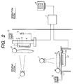
- Fig. 2 is a view for explaining a sensing system.
- Fig. 3 is a view showing details of the control section of the sensing system shown in Fig. 2.
- an upright stand 9 and table 11 each having a sensor unit are prepared in a sensing room and connected to a control section 7 in an operation room.
- a patient 2 stands first in front of the upright stand 9 and is appropriately positioned.
- An X-ray technician returns to the operation room and presses an X-ray radiation switch.
- X-rays are radiated from an X-ray generation apparatus 1 and transmitted through the patient 2.
- the X-rays having internal information of the patient 2 become incident on the sensor unit 3.
- the sensor unit 3 includes a solid-state image sensing apparatus constructed by bonding a phosphor 5 for converting X-rays into visible light proportional to the intensity of the X-rays to a photoelectric conversion apparatus 6 for converting the visible light into an electrical signal proportional to the light intensity.
- the photoelectric conversion apparatus requires several seconds for the transit period in which the apparatus shifts from the sleep state (low current state) in the nonuse mode to the ready state (normal current state).
- the X-ray image data converted into an electrical signal by the photoelectric conversion apparatus 6 is A/D-converted, transferred to the control section 7 as digital data, and displayed on display section 8 in the operation room and display section 10 in the sensing room.
- the X-ray technician Since several seconds are normally required from X-ray radiation to image display, the X-ray technician enters the sensing room to attend the patient 2 immediately after X-ray radiation and confirms the image on the display section 10. If the X-ray image is normal, the X-ray technician presses a switch 14 as a selection means attached to the side surface portion of the sensing table 11. The X-ray technician positions the patient 2 to prepare for sensing on the table 11. The state of the switch 14 is monitored by the control section 7. When the switch 14 is pressed, the upright stand 9 is set in the sleep state, and the sensing table 11 is shifted to the ready state. Each of the switches 13 and 14 has a lamp indicating the state of the sensor. The lamp of the switch 13 is OFF.
- the lamp of the switch 14 blinks when the sensor is transiting to the ready state, and is turned on in the ready state. A transit time of several seconds is required until the ready state is set, as described above. However, the ready state is set while the patient is being positioned.
- the X-ray technician returns to the operation room and immediately switches the X-ray radiation switch to sense an image.
- a signal SW_sg1 from the switch 13 can be simultaneously input to an input buffer B11 21 connected to a data bus 28 of a CPU 26, and an interrupt controller ICNT 25.
- a signal SW_sg2 from the switch 14 can also be simultaneously input to an input buffer B12 23 connected to the data bus 28 of the CPU 26, and the interrupt controller ICNT 25.
- the interrupt controller ICNT 25 monitors these signals and, when one of the signals is enabled, generates an interrupt signal INT_sg to the CPU 26.
- the CPU 26 reads the input buffer B11 21 and input buffer B12 23 on the data bus, thereby determining the pressed switch.
- the CPU 26 detects the signal SW_sg2.
- a command for setting the sleep state is transmitted from a serial IF controller SC1 22 connected to the data bus 28 to the sensor unit 3 through a command line Cmd1.
- a command for setting the ready state is transmitted from a serial IF controller SC2 24 to a sensor unit 17 through a command line Cmd2.
- two sensor units are used. However, three or more sensor units may be used.
- the switch 14 is located on the side surface of the table 11. However, the switch 14 can be located at an optimum portion in accordance with the sensing operation of the X-ray technician who uses this switch.
- a sensor unit in the nonuse mode is set in the sleep state, and that in the use mode is set in the ready state.
- a sensor unit in the nonuse mode may be set in a power-OFF state, and that in the use mode may be set in a power-ON state.
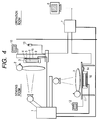
- Fig. 4 is a view for explaining a sensing system.
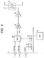
- Fig. 5 is a view showing details of the X-ray generation apparatus of the sensing system.
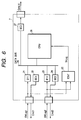
- Fig. 6 is a view showing details of the control section of the sensing system.
- the operation of the second embodiment is the same as that of the first embodiment except that sensor units incorporate phototimers 15 and 16, respectively, and the sensing time can be controlled in accordance with the X-ray dose.
- AEC Auto Exposure Control
- a phosphor is mounted on an element having a photoelectric effect and made to generate charges proportional to X-rays. When the charges reach a predetermined amount or more, a signal for cutting off the X-rays is output to the X-ray generation apparatus.
- an element having a photoelectric effect a semiconductor element such as a photodiode can be used.
- a device which extracts visible light from a phosphor by a fiber and amplifies the light using a photomultiplier.
- the phototimers are connected to an X-ray generation apparatus 1, which is connected to a control section 7 such that they can communicate with each other.
- the control section 7 transfers a command to the X-ray generation apparatus 1 to switch between the phototimers 15 and 16 simultaneously with switching the sensor unit.
- the control section of this embodiment has a serial IF controller SC3 27 connected to a data bus 28, unlike the control section of the first embodiment, to transmit a command for switching between the phototimers 15 and 16 to a command line Cmd_X, as shown in Fig. 6.
- the X-ray generation apparatus 1 controls the X-ray generation timing in accordance with the output from the selected phototimer.
- the X-ray generation apparatus 1 receives the switching request command for the phototimer 15 through the command line Cmd_X from the control section 7.
- a CPU 32 receives the command through a serial IF controller SC 31 and switches a multiplexer MUX 34 in accordance with the output signal from an output register B 33, thereby switching the signal of the phototimer from Photo_s1 to Photo_sg2.
- the output from the multiplexer MUX 34 is compared with a predetermined voltage Vcmp by a comparator CMP 35.
- a relay driving circuit Dr 36 disconnects a relay R 37 for ON/OFF-controlling X-ray generation.
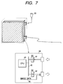
- each of sensor unit changeover switches 13 and 14 described in the first and second embodiments is connected to a control circuit 44 belonging to the photoelectric conversion apparatus in the sensor unit.
- the line of a switch 20 is connected to an input register B1 41 connected to the data bus of a CPU 43, so the CPU 43 can monitor the state of the switch 20.
- the CPU 43 When the switch 20 is pressed, and the CPU 43 detects it, the CPU 43 writes a signal representing it in an output register B2 42 connected to a data bus 45.
- the output from the output register B2 42 is connected to a control section 7 of the main body together with an image data line 46 for sending image data.
- the control section 7 is requested to switch the sensor unit having the pressed switch 20 to the ready state.
- switch enable and disable items of an X-ray sensor unit are provided in the user interface section of the control section 7, and the switch 13 or 14 is disabled as needed.
- the X-ray technician can switch the sensor unit at an effective timing, and an efficient sensing sequence can be realized.
Landscapes
- Health & Medical Sciences (AREA)
- Life Sciences & Earth Sciences (AREA)
- Engineering & Computer Science (AREA)
- Medical Informatics (AREA)
- General Health & Medical Sciences (AREA)
- Physics & Mathematics (AREA)
- Biomedical Technology (AREA)
- Heart & Thoracic Surgery (AREA)
- Nuclear Medicine, Radiotherapy & Molecular Imaging (AREA)
- Optics & Photonics (AREA)
- Pathology (AREA)
- Radiology & Medical Imaging (AREA)
- Biophysics (AREA)
- Veterinary Medicine (AREA)
- Molecular Biology (AREA)
- Surgery (AREA)
- Animal Behavior & Ethology (AREA)
- High Energy & Nuclear Physics (AREA)
- Public Health (AREA)
- Toxicology (AREA)
- Computer Vision & Pattern Recognition (AREA)
- Mathematical Physics (AREA)
- Apparatus For Radiation Diagnosis (AREA)
- Transforming Light Signals Into Electric Signals (AREA)
- Facsimile Heads (AREA)
- Closed-Circuit Television Systems (AREA)
- Measurement Of Radiation (AREA)
Abstract
Description
Claims (12)
- A sensing system comprising:a plurality of sensor units;a plurality of selection means arranged in correspondence with said plurality of sensor units respectively, for selecting the corresponding sensor units; andcontrol means for setting a sensor unit selected by said selection means in a ready state and an unselected sensor unit in a sleep state.
- A sensing system comprising:a plurality of sensor units;a plurality of selection means arranged in correspondence with said plurality of sensor units respectively, for selecting the corresponding sensor units; andcontrol means for powering on a sensor unit selected by said selection means and powering off an unselected sensor unit.
- A system according to claim 1, wherein said plurality of selection means are connected to said plurality of sensor units corresponding thereto, respectively.
- A system according to claim 1, further comprising electromagnetic wave generation means for irradiating said sensor unit with an electromagnetic wave, and wherein a generation time of the electromagnetic wave is controlled in accordance with a dose.
- A system according to claim 4, wherein each of said sensor units comprises a phototimer which outputs a signal for turning off generation of the electromagnetic wave to said electromagnetic wave generation means in accordance with a signal amount generated in said sensor.
- A system according to claim 5, wherein said control means comprises means for selecting said phototimer of the selected sensor unit.
- A system according to claim 1, wherein said control means comprises means for switching between an enable state and a disable state of selection by said selection means.
- A system according to claim 2, wherein said plurality of selection means are connected to said plurality of sensor units corresponding thereto, respectively.
- A system according to claim 2, further comprising electromagnetic wave generation means for irradiating said sensor unit with an electromagnetic wave, and wherein a generation time of the electromagnetic wave is controlled in accordance with a dose.
- A system according to claim 9, wherein each of said sensor units comprises a phototimer which outputs a signal for turning off generation of the electromagnetic wave to said electromagnetic wave generation means in accordance with a signal amount generated in said sensor.
- A system according to claim 10, wherein said control means comprises means for selecting said phototimer of the selected sensor unit.
- A system according to claim 2, wherein said control means comprises means for switching between an enable state and a disable state of selection by said selection means.
Applications Claiming Priority (2)
| Application Number | Priority Date | Filing Date | Title |
|---|---|---|---|
| JP11962999 | 1999-04-27 | ||
| JP11962999A JP3890163B2 (en) | 1999-04-27 | 1999-04-27 | Shooting system |
Publications (3)
| Publication Number | Publication Date |
|---|---|
| EP1048268A2 true EP1048268A2 (en) | 2000-11-02 |
| EP1048268A3 EP1048268A3 (en) | 2001-06-13 |
| EP1048268B1 EP1048268B1 (en) | 2005-04-20 |
Family
ID=14766182
Family Applications (1)
| Application Number | Title | Priority Date | Filing Date |
|---|---|---|---|
| EP00303521A Expired - Lifetime EP1048268B1 (en) | 1999-04-27 | 2000-04-26 | Image sensing system |
Country Status (4)
| Country | Link |
|---|---|
| US (3) | US6707880B2 (en) |
| EP (1) | EP1048268B1 (en) |
| JP (1) | JP3890163B2 (en) |
| DE (1) | DE60019487D1 (en) |
Cited By (2)
| Publication number | Priority date | Publication date | Assignee | Title |
|---|---|---|---|---|
| US7006598B2 (en) * | 2002-08-09 | 2006-02-28 | Canon Kabushiki Kaisha | Imaging method and apparatus with exposure control |
| US7148487B2 (en) | 2002-08-27 | 2006-12-12 | Canon Kabushiki Kaisha | Image sensing apparatus and method using radiation |
Families Citing this family (28)
| Publication number | Priority date | Publication date | Assignee | Title |
|---|---|---|---|---|
| JP3890163B2 (en) * | 1999-04-27 | 2007-03-07 | キヤノン株式会社 | Shooting system |
| JP3848082B2 (en) * | 2000-12-27 | 2006-11-22 | キヤノン株式会社 | X-ray imaging apparatus and method, control apparatus and method |
| JP4591804B2 (en) * | 2001-03-19 | 2010-12-01 | コニカミノルタホールディングス株式会社 | Radiography equipment |
| US6879661B2 (en) * | 2001-03-19 | 2005-04-12 | Konica Corporation | Radiographing apparatus including a control section for establishing a standby mode in a radiographing section |
| US20040028174A1 (en) * | 2002-05-31 | 2004-02-12 | Jacob Koren | Distributed and redundant computed radiography systems and methods |
| JP2004337343A (en) * | 2003-05-15 | 2004-12-02 | Fuji Photo Film Co Ltd | Radiation dose detector |
| US7177393B2 (en) * | 2004-07-21 | 2007-02-13 | Kabushiki Kaisha Toshiba | X-ray imaging apparatus |
| US7317190B2 (en) * | 2004-09-24 | 2008-01-08 | General Electric Company | Radiation absorbing x-ray detector panel support |
| US7046764B1 (en) | 2004-10-04 | 2006-05-16 | General Electric Company | X-ray detector having an accelerometer |
| US7866163B2 (en) * | 2004-10-04 | 2011-01-11 | General Electric Company | Radiographic detector docking station with dynamic environmental control |
| US7189972B2 (en) * | 2004-10-04 | 2007-03-13 | General Electric Company | X-ray detector with impact absorbing cover |
| US7342998B2 (en) * | 2004-11-18 | 2008-03-11 | General Electric Company | X-ray detector quick-connect connection system |
| US7581885B2 (en) * | 2004-11-24 | 2009-09-01 | General Electric Company | Method and system of aligning x-ray detector for data acquisition |
| US7381964B1 (en) | 2004-11-24 | 2008-06-03 | General Electric Company | Method and system of x-ray data calibration |
| DE102007020014B4 (en) * | 2007-04-27 | 2009-07-16 | Siemens Ag | imaging device |
| KR101085196B1 (en) * | 2008-05-30 | 2011-11-21 | 이종인 | Digital x-ray imaging device |
| WO2010073894A1 (en) | 2008-12-24 | 2010-07-01 | コニカミノルタエムジー株式会社 | Portable radiation image capturing apparatus and radiation image capturing system |
| JP2013005821A (en) * | 2009-10-14 | 2013-01-10 | Konica Minolta Medical & Graphic Inc | Radiation image capturing system |
| JP2011189114A (en) * | 2010-02-17 | 2011-09-29 | Canon Inc | Radiation imaging apparatus, radiation generating apparatus, radiation imaging system, and processing method thereof |
| WO2011142157A1 (en) | 2010-05-12 | 2011-11-17 | コニカミノルタエムジー株式会社 | Radiation image capturing system |
| WO2011145377A1 (en) | 2010-05-17 | 2011-11-24 | コニカミノルタエムジー株式会社 | Radiographic-image processing device |
| CN102466791B (en) * | 2010-11-18 | 2015-02-04 | Ge医疗系统环球技术有限公司 | System of wireless detector in medical system and method thereof |
| US20130322590A1 (en) * | 2011-11-19 | 2013-12-05 | Francesco Venneri | Extension of methods to utilize fully ceramic micro-encapsulated fuel in light water reactors |
| JP2013176407A (en) | 2012-02-28 | 2013-09-09 | Konica Minolta Inc | Radiographic image pickup system |
| KR20150040768A (en) * | 2013-10-07 | 2015-04-15 | 삼성전자주식회사 | X ray apparatusand x ray detector |
| JP2015167603A (en) | 2014-03-05 | 2015-09-28 | コニカミノルタ株式会社 | Imaging stand |
| JP6881907B2 (en) * | 2016-07-22 | 2021-06-02 | キヤノン株式会社 | Radiation imaging equipment, radiography systems, radiography methods, and programs |
| JP2025086229A (en) * | 2023-11-27 | 2025-06-06 | キヤノン株式会社 | Radiography control device and radiation photography system |
Family Cites Families (13)
| Publication number | Priority date | Publication date | Assignee | Title |
|---|---|---|---|---|
| DE1044350B (en) | 1957-06-15 | 1958-11-20 | Mueller C H F Ag | Circuit arrangement for X-ray devices for the representation of body layers |
| NL7611420A (en) | 1976-10-15 | 1978-04-18 | Optische Ind De Oude Delft Nv | TOMETRIC SYSTEM WITH DEVICES FOR SELECTING THE FRAMEWORK OF A DISPLAYED IMAGE. |
| DE2734040C2 (en) | 1977-07-28 | 1981-09-17 | Philips Patentverwaltung Gmbh, 2000 Hamburg | X-ray diagnostic generator for several X-ray examination devices |
| US5361215A (en) * | 1987-05-27 | 1994-11-01 | Siege Industries, Inc. | Spa control system |
| US5084911A (en) | 1989-01-10 | 1992-01-28 | Eastman Kodak Company | X-ray phototimer |
| US5001735A (en) * | 1989-07-31 | 1991-03-19 | Picker International, Inc. | X-ray dose compensation for radiographic apparatus with kV ripple |
| JPH03266573A (en) * | 1990-03-16 | 1991-11-27 | Hitachi Medical Corp | X-ray image input device |
| US5313241A (en) * | 1992-11-25 | 1994-05-17 | Eastman Kodak Company | Processor diagnostics using switch settings |
| DE4415770A1 (en) * | 1993-06-30 | 1995-01-12 | Siemens Ag | X-ray system |
| JPH10164437A (en) * | 1996-11-26 | 1998-06-19 | Canon Inc | Radiation imaging apparatus and radiation imaging element driving method |
| US5867561A (en) * | 1997-07-30 | 1999-02-02 | General Electric Company | Medical diagnostic imaging system with power conserving control apparatus |
| US6501827B1 (en) * | 1998-09-29 | 2002-12-31 | Canon Kabushiki Kaisha | Examination system, image processing apparatus and method, medium, and x-ray photographic system |
| JP3890163B2 (en) * | 1999-04-27 | 2007-03-07 | キヤノン株式会社 | Shooting system |
-
1999
- 1999-04-27 JP JP11962999A patent/JP3890163B2/en not_active Expired - Fee Related
-
2000
- 2000-04-21 US US09/553,859 patent/US6707880B2/en not_active Expired - Fee Related
- 2000-04-26 EP EP00303521A patent/EP1048268B1/en not_active Expired - Lifetime
- 2000-04-26 DE DE60019487T patent/DE60019487D1/en not_active Expired - Fee Related
-
2003
- 2003-08-18 US US10/642,232 patent/US6977990B2/en not_active Expired - Fee Related
-
2005
- 2005-10-24 US US11/255,939 patent/US7110501B2/en not_active Expired - Fee Related
Cited By (4)
| Publication number | Priority date | Publication date | Assignee | Title |
|---|---|---|---|---|
| US7006598B2 (en) * | 2002-08-09 | 2006-02-28 | Canon Kabushiki Kaisha | Imaging method and apparatus with exposure control |
| US7231018B2 (en) | 2002-08-09 | 2007-06-12 | Canon Kabushiki Kaisha | Imaging method and apparatus with exposure control |
| US7368724B2 (en) | 2002-08-09 | 2008-05-06 | Canon Kabushiki Kaisha | Imaging method and apparatus with exposure control |
| US7148487B2 (en) | 2002-08-27 | 2006-12-12 | Canon Kabushiki Kaisha | Image sensing apparatus and method using radiation |
Also Published As
| Publication number | Publication date |
|---|---|
| US6707880B2 (en) | 2004-03-16 |
| JP3890163B2 (en) | 2007-03-07 |
| EP1048268A3 (en) | 2001-06-13 |
| US20020172326A1 (en) | 2002-11-21 |
| US6977990B2 (en) | 2005-12-20 |
| DE60019487D1 (en) | 2005-05-25 |
| EP1048268B1 (en) | 2005-04-20 |
| US20040071264A1 (en) | 2004-04-15 |
| US7110501B2 (en) | 2006-09-19 |
| JP2000308630A (en) | 2000-11-07 |
| US20060039534A1 (en) | 2006-02-23 |
Similar Documents
| Publication | Publication Date | Title |
|---|---|---|
| EP1048268B1 (en) | Image sensing system | |
| KR100625800B1 (en) | X-ray imaging apparatus | |
| JPH11155847A (en) | Radiation imaging apparatus and driving method | |
| JP2002248095A (en) | X-ray digital imaging device | |
| CN100469312C (en) | X-ray image diagnostic device | |
| JP2004141473A (en) | X-ray imaging system | |
| JP4708576B2 (en) | Radiation imaging apparatus and control method | |
| US20180153496A1 (en) | Control apparatus for radiographic system | |
| JP6164877B2 (en) | Control device, radiation imaging apparatus, radiation imaging system, control method and program for radiation imaging apparatus | |
| US5559850A (en) | X-ray diagnostics installation | |
| US20180140268A1 (en) | Radiographic apparatus and radiographic system | |
| JP2016043153A (en) | Portable radiographic imaging apparatus and radiographic imaging system | |
| JP6904687B2 (en) | Radiation imaging device and its control method | |
| JP5570351B2 (en) | Console, input terminal, and X-ray imaging system | |
| JP2001066720A (en) | Imaging device, imaging system, imaging method, and storage medium | |
| JP2010012060A (en) | Portable radiation image detector and radiation image photographing system | |
| JP2022053999A (en) | Radiographic apparatus, control method thereof, radiographic system, and program | |
| JP5460626B2 (en) | Radiation imaging system, control device, and control method | |
| JP6157154B2 (en) | X-ray image detection system | |
| JP2023087159A (en) | Radiographic apparatus and program | |
| JP5777279B2 (en) | Radiography system, control method, and program | |
| JP2021115223A (en) | Power control device and its control method, and radiography system | |
| JP6072150B2 (en) | Radiography system | |
| JP4574336B2 (en) | X-ray equipment | |
| JP2026047628A (en) | Radiography system and radiography apparatus |
Legal Events
| Date | Code | Title | Description |
|---|---|---|---|
| PUAI | Public reference made under article 153(3) epc to a published international application that has entered the european phase |
Free format text: ORIGINAL CODE: 0009012 |
|
| AK | Designated contracting states |
Kind code of ref document: A2 Designated state(s): DE FR GB IT NL |
|
| AX | Request for extension of the european patent |
Free format text: AL;LT;LV;MK;RO;SI |
|
| PUAL | Search report despatched |
Free format text: ORIGINAL CODE: 0009013 |
|
| AK | Designated contracting states |
Kind code of ref document: A3 Designated state(s): AT BE CH CY DE DK ES FI FR GB GR IE IT LI LU MC NL PT SE |
|
| AX | Request for extension of the european patent |
Free format text: AL;LT;LV;MK;RO;SI |
|
| 17P | Request for examination filed |
Effective date: 20011024 |
|
| AKX | Designation fees paid |
Free format text: DE FR GB IT NL |
|
| 17Q | First examination report despatched |
Effective date: 20030625 |
|
| GRAP | Despatch of communication of intention to grant a patent |
Free format text: ORIGINAL CODE: EPIDOSNIGR1 |
|
| GRAS | Grant fee paid |
Free format text: ORIGINAL CODE: EPIDOSNIGR3 |
|
| GRAA | (expected) grant |
Free format text: ORIGINAL CODE: 0009210 |
|
| AK | Designated contracting states |
Kind code of ref document: B1 Designated state(s): DE FR GB IT NL |
|
| PG25 | Lapsed in a contracting state [announced via postgrant information from national office to epo] |
Ref country code: IT Free format text: LAPSE BECAUSE OF FAILURE TO SUBMIT A TRANSLATION OF THE DESCRIPTION OR TO PAY THE FEE WITHIN THE PRESCRIBED TIME-LIMIT;WARNING: LAPSES OF ITALIAN PATENTS WITH EFFECTIVE DATE BEFORE 2007 MAY HAVE OCCURRED AT ANY TIME BEFORE 2007. THE CORRECT EFFECTIVE DATE MAY BE DIFFERENT FROM THE ONE RECORDED. Effective date: 20050420 Ref country code: NL Free format text: LAPSE BECAUSE OF FAILURE TO SUBMIT A TRANSLATION OF THE DESCRIPTION OR TO PAY THE FEE WITHIN THE PRESCRIBED TIME-LIMIT Effective date: 20050420 |
|
| REG | Reference to a national code |
Ref country code: GB Ref legal event code: FG4D |
|
| REF | Corresponds to: |
Ref document number: 60019487 Country of ref document: DE Date of ref document: 20050525 Kind code of ref document: P |
|
| NLV1 | Nl: lapsed or annulled due to failure to fulfill the requirements of art. 29p and 29m of the patents act | ||
| PG25 | Lapsed in a contracting state [announced via postgrant information from national office to epo] |
Ref country code: DE Free format text: LAPSE BECAUSE OF NON-PAYMENT OF DUE FEES Effective date: 20051101 |
|
| PLBE | No opposition filed within time limit |
Free format text: ORIGINAL CODE: 0009261 |
|
| STAA | Information on the status of an ep patent application or granted ep patent |
Free format text: STATUS: NO OPPOSITION FILED WITHIN TIME LIMIT |
|
| 26N | No opposition filed |
Effective date: 20060123 |
|
| EN | Fr: translation not filed | ||
| PG25 | Lapsed in a contracting state [announced via postgrant information from national office to epo] |
Ref country code: FR Free format text: LAPSE BECAUSE OF NON-PAYMENT OF DUE FEES Effective date: 20050430 |
|
| PG25 | Lapsed in a contracting state [announced via postgrant information from national office to epo] |
Ref country code: FR Free format text: LAPSE BECAUSE OF NON-PAYMENT OF DUE FEES Effective date: 20050420 |
|
| PGFP | Annual fee paid to national office [announced via postgrant information from national office to epo] |
Ref country code: GB Payment date: 20150424 Year of fee payment: 16 |
|
| GBPC | Gb: european patent ceased through non-payment of renewal fee |
Effective date: 20160426 |
|
| PG25 | Lapsed in a contracting state [announced via postgrant information from national office to epo] |
Ref country code: GB Free format text: LAPSE BECAUSE OF NON-PAYMENT OF DUE FEES Effective date: 20160426 |