JP2015167603A - Imaging stand - Google Patents

Imaging stand Download PDF

Info

Publication number
JP2015167603A
JP2015167603A JP2014042286A JP2014042286A JP2015167603A JP 2015167603 A JP2015167603 A JP 2015167603A JP 2014042286 A JP2014042286 A JP 2014042286A JP 2014042286 A JP2014042286 A JP 2014042286A JP 2015167603 A JP2015167603 A JP 2015167603A
Authority
JP
Japan
Prior art keywords
holder
radiation
type detector
cassette
panel
Prior art date
Legal status (The legal status is an assumption and is not a legal conclusion. Google has not performed a legal analysis and makes no representation as to the accuracy of the status listed.)
Ceased
Application number
JP2014042286A
Other languages
Japanese (ja)
Inventor
厚司 鈴木
Koji Suzuki
厚司 鈴木
Current Assignee (The listed assignees may be inaccurate. Google has not performed a legal analysis and makes no representation or warranty as to the accuracy of the list.)
Konica Minolta Inc
Original Assignee
Konica Minolta Inc
Priority date (The priority date is an assumption and is not a legal conclusion. Google has not performed a legal analysis and makes no representation as to the accuracy of the date listed.)
Filing date
Publication date
Application filed by Konica Minolta Inc filed Critical Konica Minolta Inc
Priority to JP2014042286A priority Critical patent/JP2015167603A/en
Priority to US14/637,072 priority patent/US9462982B2/en
Publication of JP2015167603A publication Critical patent/JP2015167603A/en
Ceased legal-status Critical Current

Links

Images

Classifications

    • AHUMAN NECESSITIES
    • A61MEDICAL OR VETERINARY SCIENCE; HYGIENE
    • A61BDIAGNOSIS; SURGERY; IDENTIFICATION
    • A61B6/00Apparatus for radiation diagnosis, e.g. combined with radiation therapy equipment
    • A61B6/42Apparatus for radiation diagnosis, e.g. combined with radiation therapy equipment with arrangements for detecting radiation specially adapted for radiation diagnosis
    • A61B6/4208Apparatus for radiation diagnosis, e.g. combined with radiation therapy equipment with arrangements for detecting radiation specially adapted for radiation diagnosis characterised by using a particular type of detector
    • A61B6/4233Apparatus for radiation diagnosis, e.g. combined with radiation therapy equipment with arrangements for detecting radiation specially adapted for radiation diagnosis characterised by using a particular type of detector using matrix detectors
    • AHUMAN NECESSITIES
    • A61MEDICAL OR VETERINARY SCIENCE; HYGIENE
    • A61BDIAGNOSIS; SURGERY; IDENTIFICATION
    • A61B6/00Apparatus for radiation diagnosis, e.g. combined with radiation therapy equipment
    • A61B6/42Apparatus for radiation diagnosis, e.g. combined with radiation therapy equipment with arrangements for detecting radiation specially adapted for radiation diagnosis
    • A61B6/4283Apparatus for radiation diagnosis, e.g. combined with radiation therapy equipment with arrangements for detecting radiation specially adapted for radiation diagnosis characterised by a detector unit being housed in a cassette
    • AHUMAN NECESSITIES
    • A61MEDICAL OR VETERINARY SCIENCE; HYGIENE
    • A61BDIAGNOSIS; SURGERY; IDENTIFICATION
    • A61B6/00Apparatus for radiation diagnosis, e.g. combined with radiation therapy equipment
    • A61B6/44Constructional features of apparatus for radiation diagnosis
    • A61B6/4429Constructional features of apparatus for radiation diagnosis related to the mounting of source units and detector units
    • AHUMAN NECESSITIES
    • A61MEDICAL OR VETERINARY SCIENCE; HYGIENE
    • A61BDIAGNOSIS; SURGERY; IDENTIFICATION
    • A61B6/00Apparatus for radiation diagnosis, e.g. combined with radiation therapy equipment
    • A61B6/54Control of apparatus or devices for radiation diagnosis
    • A61B6/547Control of apparatus or devices for radiation diagnosis involving tracking of position of the device or parts of the device
    • AHUMAN NECESSITIES
    • A61MEDICAL OR VETERINARY SCIENCE; HYGIENE
    • A61BDIAGNOSIS; SURGERY; IDENTIFICATION
    • A61B6/00Apparatus for radiation diagnosis, e.g. combined with radiation therapy equipment
    • A61B6/40Apparatus for radiation diagnosis, e.g. combined with radiation therapy equipment with arrangements for generating radiation specially adapted for radiation diagnosis
    • AHUMAN NECESSITIES
    • A61MEDICAL OR VETERINARY SCIENCE; HYGIENE
    • A61BDIAGNOSIS; SURGERY; IDENTIFICATION
    • A61B6/00Apparatus for radiation diagnosis, e.g. combined with radiation therapy equipment
    • A61B6/54Control of apparatus or devices for radiation diagnosis
    • A61B6/542Control of apparatus or devices for radiation diagnosis involving control of exposure
    • AHUMAN NECESSITIES
    • A61MEDICAL OR VETERINARY SCIENCE; HYGIENE
    • A61BDIAGNOSIS; SURGERY; IDENTIFICATION
    • A61B6/00Apparatus for radiation diagnosis, e.g. combined with radiation therapy equipment
    • A61B6/58Testing, adjusting or calibrating apparatus or devices for radiation diagnosis
    • A61B6/588Setting distance between source unit and detector unit

Abstract

PROBLEM TO BE SOLVED: To provide an affordable imaging stand capable of easily and highly accurately changing the orientation and the position of a cassette-type detector held in a holder, without removing and reinstalling the cassette-type detector from and to the holder.SOLUTION: An imaging stand 1 comprises: a holder 6 for holding an installed cassette-type detector D; and a supporting member 7 for supporting the holder 6 from a back surface side. The holder 6 has a rotation center 6x provided to a position shifted from the position corresponding to a center C of a radiation incidence surface R of the cassette-type detector D held in the holder 6. When the holder 6 with the cassette-type detector D held therein is rotated relative to the supporting member 7, the rotation center 6x of the holder 6 moves linearly relative to the supporting member 7 as the holder 6 rotates to thereby change the orientation and position of the cassette-type detector D.

Description

本発明は、撮影台に係り、特に、CRカセッテやFPDカセッテを装填して撮影に使用するための撮影台に関する。   The present invention relates to an imaging stand, and more particularly, to an imaging stand for loading a CR cassette or FPD cassette for use in shooting.

病気診断等を目的として、X線画像に代表される放射線画像が広く用いられている。こうした医療用の放射線画像は、従来からスクリーンフィルムを用いて撮影されていたが、放射線画像のデジタル化を図るために輝尽性蛍光体シートを用いたCR(Computed Radiography)装置が開発された。そして、最近では、照射された放射線を放射線検出素子で検出してデジタルの画像データとして取得する放射線画像撮影装置(Flat Panel Detector)が開発されている。   For the purpose of disease diagnosis and the like, radiation images represented by X-ray images are widely used. Conventionally, such medical radiographic images have been taken using a screen film. In order to digitize radiographic images, CR (Computed Radiography) apparatuses using stimulable phosphor sheets have been developed. Recently, a radiation image capturing apparatus (Flat Panel Detector) that detects irradiated radiation with a radiation detection element and acquires it as digital image data has been developed.

CR装置では、従来から、輝尽性蛍光体シート等をカセッテ状の筐体内に収納したCRカセッテを、撮影台(ブッキー撮影台、ディテクターホルダー等ともいう。)に装填して放射線画像撮影が行われることが多い。また、放射線画像撮影装置は、従来、支持台等と一体的に形成された、いわゆる専用機として開発されたが(例えば特許文献1、2参照)、近年、放射線検出素子等を筐体内に収納して可搬とした可搬型の放射線画像撮影装置が開発され、実用化されている(例えば特許文献3、4参照)。なお、このような可搬型の放射線画像撮影装置を、以下、単にFPDカセッテという。また、以下、CRカセッテとFPDカセッテとをまとめてカセッテ型ディテクターという。   Conventionally, a CR apparatus in which a photostimulable phosphor sheet or the like is housed in a cassette-shaped housing is loaded into an imaging table (also referred to as a bucky imaging table or a detector holder) to perform radiographic imaging. Often. In addition, the radiographic imaging apparatus has been developed as a so-called dedicated machine that is integrally formed with a support base or the like (see, for example, Patent Documents 1 and 2). A portable radiographic imaging device that has been made portable has been developed and put into practical use (see, for example, Patent Documents 3 and 4). Hereinafter, such a portable radiographic imaging apparatus is simply referred to as an FPD cassette. Hereinafter, the CR cassette and the FPD cassette are collectively referred to as a cassette type detector.

一方、カセッテ型ディテクターを装填するブッキーを備える撮影台も、種々開発が進められている(例えば特許文献5等参照)。そして、撮影台は、10×12インチ(四切)や11×14インチ(大四切)、14×14インチ(大角)、14×17インチ(半切)、17×17インチ等の各サイズのカセッテ型ディテクターが装填することができるように構成されることが多い。   On the other hand, various developments have been made on a photographing stand equipped with a bucky for loading a cassette type detector (see, for example, Patent Document 5). The photographing stand has various sizes such as 10 × 12 inches (four cuts), 11 × 14 inches (large four cuts), 14 × 14 inches (large angle), 14 × 17 inches (half cuts), 17 × 17 inches, etc. Often configured so that a cassette-type detector can be loaded.

その際、例えば14×17インチのカセッテ型ディテクターを撮影台に装填して撮影を行う場合、カセッテ型ディテクターDは、図16(A)に示すように撮影台100のブッキー101内のホルダー102の上方に横向きに装填されたり、図16(B)に示すようにホルダー102の上下方向の中央のポジションに横向きに装填されたり、或いは、図17(A)に示すように、ホルダー102の左右方向の中央のポジションに縦向きに装填される等して用いられる。   At that time, for example, when a 14 × 17 inch cassette type detector is loaded on the imaging table and imaging is performed, the cassette type detector D is connected to the holder 102 in the bucky 101 of the imaging table 100 as shown in FIG. It is loaded sideways upward, as shown in FIG. 16B, loaded sideways at the center position in the vertical direction of the holder 102, or as shown in FIG. It is used, for example, by being loaded vertically in the center position.

なお、以下、カセッテ型ディテクターDを、図16(A)のようにホルダー102の上方に横向きに装填する場合を「横向き上方」といい(Landscape top等ともいう。)、図16(B)のようにホルダー102の上下方向の中央のポジションに横向きに装填する場合を「横向き中央」といい(Landscape center等ともいう。)、図17(A)のようにホルダー102の左右方向の中央のポジションに縦向きに装填する場合を「縦向き中央」という(Portrait等ともいう。)。   Hereinafter, the case where the cassette type detector D is loaded horizontally above the holder 102 as shown in FIG. 16A is referred to as “landscape top” (also referred to as “Landscape top”), and FIG. In this way, the case where the holder 102 is loaded horizontally at the center position in the vertical direction is called “landscape center” (also referred to as “Landscape center”), and the center position in the left-right direction of the holder 102 as shown in FIG. The case of loading in the vertical direction is called “vertical center” (also called Portrait etc.).

また、例えば17×17インチのカセッテ型ディテクターDを撮影台に装填して撮影を行う場合には、カセッテ型ディテクターDは、図17(B)に示すようにホルダー102に装填される。そして、横向き上方に配置された14×17インチのカセッテ型ディテクターD(図16(A)参照)の上端の位置と、縦向き中央に配置されたカセッテ型ディテクターD(図17(A)参照)の上端の位置と、17×17インチのカセッテ型ディテクターD(図17(B)参照)の上端の位置とは、すべて同じ位置(すなわち床面等からの高さ)になるように構成される。   For example, when the 17 × 17 inch cassette type detector D is loaded on the photographing stand and photographing is performed, the cassette type detector D is loaded in the holder 102 as shown in FIG. And the position of the upper end of the cassette type detector D (refer FIG. 16 (A)) of 14 * 17 inches arrange | positioned horizontally upward, and the cassette type detector D (refer FIG. 17 (A)) arrange | positioned in the vertical direction center. The upper end position of the 17 × 17 inch cassette-type detector D (see FIG. 17B) is all configured to be the same position (that is, the height from the floor or the like). .

特許第3890163号公報Japanese Patent No. 3890163 特開平9−73144号公報JP-A-9-73144 特開2006−58124号公報JP 2006-58124 A 特開平6−342099号公報JP-A-6-342099 特開2005−21233号公報JP 2005-21233 A

ところで、従来の撮影台では、装填されているカセッテ型ディテクター(すなわちFPDカセッテやCRカセッテ)の向きや配置を変える場合、装填されているカセッテ型ディテクターDを撮影台100のホルダー102から一旦抜き出し、装填時にカセッテ型ディテクターDを保持するガイド103の位置を調整する等したうえで、再度、カセッテ型ディテクターDをホルダー102に差し込む等の複雑な操作を行う必要があった。   By the way, in the conventional photographing stand, when changing the orientation and arrangement of the loaded cassette type detector (that is, FPD cassette or CR cassette), the loaded cassette type detector D is once extracted from the holder 102 of the photographing stand 100, It is necessary to perform a complicated operation such as inserting the cassette type detector D into the holder 102 again after adjusting the position of the guide 103 holding the cassette type detector D at the time of loading.

そのため、撮影台100における操作性が損なわれるだけでなく、上記のようにホルダー102に対してカセッテ型ディテクターDを抜き差しする際に、カセッテ型ディテクターDを落下させてしまう虞れがある。そして、カセッテ型ディテクターDを落下させると、カセッテ型ディテクターDが故障したり、カセッテ型ディテクターDが放射線技師等の操作者の足の上に落下させたり身体にぶつかる等して操作者が負傷する等の問題があった。   Therefore, not only the operability of the imaging stand 100 is impaired, but also when the cassette type detector D is inserted into and removed from the holder 102 as described above, the cassette type detector D may be dropped. When the cassette type detector D is dropped, the cassette type detector D breaks down, or the cassette type detector D is dropped on an operator's foot such as a radiologist, or the operator is injured. There was a problem such as.

そこで、このような状況を改善し、できるだけカセッテ型ディテクターDの抜き差しをせずに撮影台100におけるカセッテ型ディテクターDの向き等を変えることができるようにするために、例えば、撮影台100のホルダー102が、その背面側に設けられ、ホルダー102を背面側から支持する支持部材104に対して回動することができた回動機構付きの撮影台100も開発されている。このように構成すれば、カセッテ型ディテクターDを保持した状態でホルダー102を90°回動させることで、横向き中央(図16(B)参照)と縦向き中央(図17(A)参照)との間では容易にカセッテ型ディテクターDの向きや配置を変えることができる。   Therefore, in order to improve such a situation and change the orientation of the cassette type detector D in the photographing table 100 without inserting or removing the cassette type detector D as much as possible, for example, the holder of the photographing table 100 An imaging stand 100 with a rotation mechanism has been developed in which 102 is provided on the back side thereof and can rotate with respect to the support member 104 that supports the holder 102 from the back side. With this configuration, the holder 102 is rotated by 90 ° while holding the cassette-type detector D, so that the horizontal center (see FIG. 16B) and the vertical center (see FIG. 17A) can be obtained. The orientation and arrangement of the cassette-type detector D can be easily changed.

しかしながら、カセッテ型ディテクターDが横向き上方(図16(A)参照)の状態でホルダー102を90°回動させると、図16(A)を右や左に90°回動させると簡単に分かるように、カセッテ型ディテクターDの向きは縦向きになるが、カセッテ型ディテクターDの配置がホルダー102の左右方向の中央ではなく、右や左に寄ってしまう。そのため、ホルダー102を回動させる機構のほかに、ホルダー102内でカセッテ型ディテクターDを移動させたり、或いはホルダー102自体を移動させてカセッテ型ディテクターDの配置を調整するための機構を設けることが必要になるが、これでは撮影台100の操作性が損なわれるだけでなく、コスト面でもデメリットが生じてしまう。また、機構が複雑になると、撮影台100内でのカセッテ型ディテクターDの向きや配置を精度良く調節することが必ずしも容易でなくなる等の問題があった。   However, if the holder 102 is rotated 90 ° while the cassette type detector D is in the horizontal upward direction (see FIG. 16A), it can be easily understood by rotating the holder 102 90 ° to the right or left. In addition, the cassette type detector D is oriented vertically, but the cassette type detector D is arranged not to the right or left center of the holder 102 but to the right or left. Therefore, in addition to the mechanism for rotating the holder 102, a mechanism for moving the cassette type detector D within the holder 102 or for moving the holder 102 itself to adjust the arrangement of the cassette type detector D may be provided. Although this is necessary, this not only impairs the operability of the imaging stand 100 but also causes a disadvantage in terms of cost. In addition, when the mechanism is complicated, there is a problem that it is not always easy to accurately adjust the orientation and arrangement of the cassette type detector D in the imaging table 100.

本発明は、上記の問題点を鑑みてなされたものであり、ホルダーに保持されたカセッテ型ディテクターの向きや配置を、カセッテ型ディテクターを抜き差しすることなく容易かつ精度良く変えることが可能で、かつ、それを低コストで実現可能な撮影台を提供することを目的とする。   The present invention has been made in view of the above problems, and the orientation and arrangement of the cassette-type detector held by the holder can be easily and accurately changed without inserting or removing the cassette-type detector, and An object of the present invention is to provide a photographing stand that can be realized at low cost.

前記の問題を解決するために、本発明の撮影台は、
装填されたカセッテ型ディテクターを保持するホルダーと、
前記ホルダーを背面側から支持する支持部材と、
を備え、
前記ホルダーに保持された前記カセッテ型ディテクターの前記放射線入射面の中心に対応する位置からずれた位置に設けられた前記ホルダーの回動中心の位置から背面側の前記支持部材側に突出する軸部材に固定された円形歯車と、
前記支持部材に設けられ、前記円形歯車の歯と係合する凹凸が形成された直線歯車と、
を備え、
前記カセッテ型ディテクターを保持した状態の前記ホルダーを前記支持部材に対して回動させると、前記ホルダーの回動とともに当該ホルダーの回動中心が前記支持部材に対して直線的に移動して、前記カセッテ型ディテクターの向きおよび配置を変えるように構成されていることを特徴とする。
In order to solve the above-mentioned problem, the photographing stand of the present invention is
A holder for holding a loaded cassette-type detector;
A support member for supporting the holder from the back side;
With
A shaft member projecting from the position of the rotation center of the holder provided at a position shifted from the position corresponding to the center of the radiation incident surface of the cassette type detector held by the holder to the support member side on the back side A circular gear fixed to the
A linear gear provided on the support member and formed with concavities and convexities that engage with teeth of the circular gear;
With
When the holder holding the cassette type detector is rotated with respect to the support member, the rotation center of the holder moves linearly with respect to the support member together with the rotation of the holder, It is configured to change the orientation and arrangement of the cassette-type detector.

本発明のような方式の撮影台によれば、ホルダーに保持されたカセッテ型ディテクターの向きや配置を、カセッテ型ディテクターを抜き差しすることなく容易かつ精度良く変えることが可能となり、しかも、それを低コストで実現することが可能となる。   According to the photographing stand of the present invention, the orientation and arrangement of the cassette type detector held by the holder can be easily and accurately changed without inserting or removing the cassette type detector. It can be realized at a cost.

本実施形態に係る撮影台の外観を示す図であり、(A)は斜視図、(B)は側面図を表す。It is a figure which shows the external appearance of the imaging stand which concerns on this embodiment, (A) represents a perspective view, (B) represents a side view. 撮影台のホルダーの構成等を表し、14×17インチのパネルが横向き上方に配置された状態を表す図である。It is a figure showing the state etc. which represent the structure of the holder of an imaging stand, etc., and the 14 * 17 inch panel was arrange | positioned sideways upward. ホルダーを回動させた場合の(A)14×17インチのパネルの中心の移動の軌跡、および(B)14×17インチのパネルの中心に対応するホルダー上の点の移動の軌跡を表す図である。(A) The locus of movement of the center of the 14 × 17 inch panel and (B) the locus of movement of the point on the holder corresponding to the center of the 14 × 17 inch panel when the holder is rotated. It is. ホルダーを90°回動させることで14×17インチのパネルの向きや配置が横向き上方から縦向き中央に変わること、および14×17インチのパネルの中心が移動することを説明する図である。It is a figure explaining the direction and arrangement | positioning of a 14 * 17 inch panel changing from horizontal direction upper direction to the vertical center, and the center of a 14 * 17 inch panel moving by rotating a holder 90 degree | times. ホルダーをさらに90°回動させることで14×17インチのパネルの向きや配置が縦向き中央から横向き中央に変わること、および14×17インチのパネルの中心が移動しないことを説明する図である。It is a figure explaining the orientation and arrangement | positioning of a 14 * 17 inch panel changing from a vertical center to a horizontal center, and the center of a 14 * 17 inch panel not moving by further rotating 90 degrees of a holder. . ホルダーを270°回動させて17×17インチのパネルを装填した状態を表す図である。It is a figure showing the state which rotated the holder 270 degrees and loaded the panel of 17x17 inches. ホルダーを270°回動させた状態で17×17インチのパネルと14×17インチのパネルを装填した場合の各パネルの位置とそれぞれの中心の位置とを表す図である。It is a figure showing the position of each panel at the time of loading a 17 * 17 inch panel and a 14 * 17 inch panel in the state which rotated the holder 270 degrees, and each center position. 本実施形態における円形歯車や支持部材等の構成を表す図である。It is a figure showing composition of a circular gear, a support member, etc. in this embodiment. (A)ホルダーの回動角度が0°の場合の円形歯車と14×17インチのパネルの中心の位置等を表す図であり、(B)ホルダーを90°回動させた場合の円形歯車と14×17インチのパネルの中心の位置等を表す図である。(A) It is a figure showing the circular gear when the rotation angle of the holder is 0 °, the center position of the 14 × 17 inch panel, etc., and (B) the circular gear when the holder is rotated 90 ° It is a figure showing the position etc. of the center of a 14 * 17 inch panel. (A)ホルダーを180°回動させた場合の円形歯車と14×17インチのパネルの中心の位置等を表す図であり、(B)ホルダーを270°回動させた場合の円形歯車と14×17インチのパネルの中心に対応する点の位置等を表す図である。(A) It is a figure showing the circular gearwheel when a holder is rotated 180 degrees, the center position of a 14 * 17 inch panel, etc., (B) The circular gearwheel and 14 when a holder is rotated 270 degrees It is a figure showing the position etc. of the point corresponding to the center of * 17-inch panel. ホルダーを回動させると14×17インチのカセッテ型ディテクターの中心Cがサイクロイド曲線上を移動することを説明する図である。It is a figure explaining that the center C of a 14 * 17 inch cassette type detector moves on a cycloid curve when a holder is rotated. スライド板や棒状部材等の構成例を表す図である。It is a figure showing the structural examples, such as a slide plate and a rod-shaped member. ホルダーの回動角度が0°および90°の場合の棒状部材や第1係止爪、第2係止爪等の位置関係等を表す図である。It is a figure showing the positional relationship of a rod-shaped member, a 1st latching claw, a 2nd latching claw, etc. in case the rotation angle of a holder is 0 degree and 90 degrees. 回動角度が0°のホルダー6等を図13における左側から見た側面図である。It is the side view which looked at the holder 6 grade | etc., Whose rotation angle is 0 degree from the left side in FIG. ホルダーの回動角度が180°および270°の場合の棒状部材や第1係止爪、第2係止爪等の位置関係等を表す図である。It is a figure showing the positional relationship etc. of a rod-shaped member, a 1st latching claw, a 2nd latching claw, etc. in case the rotation angle of a holder is 180 degrees and 270 degrees. 従来の撮影台に14×17インチのカセッテ型ディテクターを(A)横向き上方に、および(B)横向き中央に装填した状態を表す図である。It is a figure showing the state which loaded the cassette type detector of 14 * 17 inches into the conventional imaging stand in (A) horizontal direction upper direction, and (B) horizontal direction center. 従来の撮影台に(A)14×17インチのカセッテ型ディテクターを縦向き中央に装填した状態を表す図であり、(B)17×17インチのカセッテ型ディテクターを装填した状態を表す図である。It is a figure showing the state which loaded the cassette type detector of (A) 14 * 17 inches vertically on the conventional imaging stand, and is a figure showing the state which loaded the cassette type detector of 17 * 17 inches. . デプスカメラを用いて放射線照射装置の放射線源の焦点とカセッテ型ディテクターの受像面との距離SIDを算出する手法等を説明する図である。It is a figure explaining the method etc. which calculate distance SID of the focus of the radiation source of a radiation irradiation apparatus, and the image receiving surface of a cassette type detector using a depth camera. ベクトルの鉛直角θ1と水平角θ2を説明する図である。It is a figure explaining the vertical angle (theta) 1 and horizontal angle (theta) 2 of a vector. カセッテ型ディテクターに入射するように放射線を照射した場合の被写体が撮影されている領域Raと撮影されていない領域Rbとを表す図である。It is a figure showing area | region Ra where the to-be-photographed object is image | photographed and the area | region Rb not image | photographed at the time of irradiating a radiation so that it may inject into a cassette type | mold detector. 放射線センサーを用いて放射線の照射範囲を計測するように構成した構成例を表す図である。It is a figure showing the structural example comprised so that the irradiation range of a radiation might be measured using a radiation sensor. 撮影された画像中に特定された放射線の範囲Rall、被写体が撮影されている領域Rcおよび撮影されていない領域Rdを表す図である。It is a figure showing the range Rall of the radiation specified in the image | photographed image, the area | region Rc where the to-be-photographed object is image | photographed, and the area | region Rd which is not imaged. 従来の放射線照射装置の放射線源の構成や焦点を説明する図であり、(A)は正面図、(B)は側面図を表す。It is a figure explaining the structure and focus of the radiation source of the conventional radiation irradiation apparatus, (A) represents a front view, (B) represents a side view. 焦点を小さくし過ぎると回転陽極の傾斜面の一部にのみ電子ビームが照射される状態になり、その部分が線状に傷むことを説明する図である。It is a figure explaining that it will be in the state where an electron beam will be irradiated only to a part of inclined surface of a rotating anode, and that part will be damaged linearly when a focus is made too small. 仮に回転陽極の傾斜を設けていない側面に電子ビームを照射した場合に焦点の縦方向の見かけの径が大きくなることを説明する図であり、(A)は側面図、(B)は正面図を表す。It is a figure explaining that the apparent diameter of the vertical direction of a focus becomes large when an electron beam is irradiated to the side surface which does not provide the inclination of a rotating anode, (A) is a side view, (B) is a front view. Represents. 本願発明者が新たに見出した構成の放射線源を表す図であり、(A)は正面図、(B)は側面図である。It is a figure showing the radiation source of the structure newly found by this inventor, (A) is a front view, (B) is a side view. 本願発明者が新たに見出した構成の放射線源の他の構成例を表す正面図である。It is a front view showing the other structural example of the radiation source of the structure newly discovered by this inventor. 図26の放射線源を用いて構成されるラインスキャン型の放射線照射装置の構成例を表す図である。It is a figure showing the structural example of the line scan type radiation irradiation apparatus comprised using the radiation source of FIG.

以下、本発明に係る撮影台の実施の形態について、図面を参照して説明する。ただし、本発明は以下の図示例のものに限定されるものではない。   DESCRIPTION OF THE PREFERRED EMBODIMENTS Embodiments of an imaging stand according to the present invention will be described below with reference to the drawings. However, the present invention is not limited to the following illustrated examples.

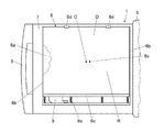
図1(A)、(B)は、本実施形態に係る撮影台の外観を示す図であり、(A)は斜視図、(B)は側面図を表す。本実施形態では、撮影台1は、ブッキー2と、ブッキー2を昇降可能に支持するスタンド3と、スタンド3等を図示しない床面等に固定するための脚部4等を備えて構成されている。   1A and 1B are views showing the appearance of a photographing stand according to this embodiment, where FIG. 1A is a perspective view and FIG. 1B is a side view. In the present embodiment, the photographic stand 1 includes a bucky 2, a stand 3 that supports the bucky 2 so as to be movable up and down, and a leg 4 for fixing the stand 3 and the like to a floor surface (not shown). Yes.

なお、図1(A)、(B)に示すように、本実施形態では、撮影台1が、ブッキー2の手前側に被写体である患者を起立させた状態(すなわち立位)で撮影を行う、いわゆる立位撮影台の場合について説明するが、図示を省略するが、例えば患者を天板等の上に横臥させた状態(すなわち臥位)で撮影を行う、いわゆる臥位撮影台の場合にも、本発明を適用することが可能である。   As shown in FIGS. 1A and 1B, in this embodiment, the imaging table 1 performs imaging in a state where the patient as a subject stands on the front side of the bucky 2 (that is, standing). In the case of the so-called standing position imaging stand, the illustration is omitted, but the illustration is omitted, but in the case of the so-called standing position imaging stand that performs imaging in a state where the patient is lying on the top board or the like (that is, lying down), for example. In addition, the present invention can be applied.

また、本実施形態においても、カセッテ型ディテクターDには、CRカセッテとFPDカセッテとが含まれる。なお、以下では、撮影台1に装填されるカセッテ型ディテクターDを単にパネルDと表現する。すなわち、以下においてパネルDという場合、CRカセッテもFPDカセッテも含まれる。さらに、以下では、撮影台1のスタンド3側(すなわち図1(A)では奥側)を背面側という。   Also in the present embodiment, the cassette type detector D includes a CR cassette and an FPD cassette. In the following, the cassette type detector D loaded on the photographing stand 1 is simply expressed as a panel D. That is, in the following, the panel D includes a CR cassette and an FPD cassette. Furthermore, below, the stand 3 side of the imaging stand 1 (that is, the back side in FIG. 1A) is referred to as the back side.

ブッキー2は、装填されるパネルD(後述する図2等参照)を収納する本体部5を備えている。本体部5は、左右いずれかの側面部に開口5aが設けられた筐体状に形成されており、開口5aには扉部5bが設けられており、扉部5bは、本体部5の背面側に設けられた図示しない蝶番構造により開閉可能とされている。そして、後述するようにパネルDが装填されて本体部5内に収納され、扉部5bが閉鎖されることで、開口5aが閉塞されて、パネルDが本体部5内に収納されるようになっている。また、本体部51の筐体の上面部には、被写体の胸部レントゲン撮影等を行う際に被写体である患者等が顎を載せるための窪み5cが設けられている。   The bucky 2 includes a main body 5 that houses a panel D to be loaded (see FIG. 2 and the like to be described later). The main body 5 is formed in a housing shape having an opening 5 a on either the left or right side surface, and the door 5 b is provided on the opening 5 a, and the door 5 b is the back surface of the main body 5. It can be opened and closed by a hinge structure (not shown) provided on the side. As will be described later, the panel D is loaded and stored in the main body 5, and the door 5 b is closed so that the opening 5 a is closed and the panel D is stored in the main body 5. It has become. In addition, a recess 5c is provided on the upper surface of the housing of the main body 51 for a patient or the like who is a subject to place his / her chin when performing chest X-ray imaging or the like of the subject.

図2に示すように、撮影台1は、ブッキー2の本体部5の内部に、装填されたパネルDを保持するホルダー6と、ホルダー6を背面側から支持する支持部材7等が収納されるようになっている。そして、支持部材7に取り付けられたハンドル8を引くことにより、図2に示すように、本体部5内部からホルダー6や支持部材7等を引き出すことができるようになっている。また、ハンドル8を押すことにより、図1(A)、(B)に示したように、ホルダー6や支持部材7等を本体部5内部に収納することができるようになっている。なお、図2では、ホルダー6に装填されている14×17インチのパネルDの向きや配置が横向き上方(図16(A)参照)である場合が示されている。また、図2における6xについては後で説明する。   As shown in FIG. 2, in the photographing stand 1, a holder 6 that holds the loaded panel D, a support member 7 that supports the holder 6 from the back side, and the like are housed inside the main body 5 of the bucky 2. It is like that. Then, by pulling the handle 8 attached to the support member 7, the holder 6, the support member 7 and the like can be pulled out from the inside of the main body 5 as shown in FIG. Further, by pressing the handle 8, the holder 6, the support member 7, etc. can be accommodated inside the main body 5 as shown in FIGS. 1 (A) and 1 (B). FIG. 2 shows a case where the orientation and arrangement of the 14 × 17 inch panel D loaded in the holder 6 is horizontally upward (see FIG. 16A). Further, 6x in FIG. 2 will be described later.

本実施形態では、ホルダー6は、装填されたパネルDを背面側から支持する背面板6aと、図2における左右方向へのパネルDの動きを規制する、背面板6aに直交するように設けられた規制板6b、6bと、図2においてパネルDの下端部分に係止する第1係止爪6cと、第1係止爪6cとは反対側に設けられ、図2では装填されたパネルDの上端部分に係止する第2係止爪6d、6dとを備えている。そして、第1係止爪6cは、図2では上下方向に平行移動できるようになっており、バネ6e等により第2係止爪6d、6dが設けられた側に付勢されている。   In this embodiment, the holder 6 is provided so as to be orthogonal to the back plate 6a that supports the loaded panel D from the back side and the back plate 6a that restricts the movement of the panel D in the left-right direction in FIG. The control plates 6b and 6b, the first locking claw 6c locked to the lower end portion of the panel D in FIG. 2, and the first locking claw 6c are provided on the opposite side of the panel D. FIG. The second locking claws 6d, 6d are provided to be locked to the upper end portion of the first locking portion. The first locking claw 6c can be translated in the vertical direction in FIG. 2, and is biased to the side where the second locking claws 6d and 6d are provided by a spring 6e or the like.

なお、ホルダー6に装填されたパネルDが図2では手前側に飛び出さないようにするために、第1係止爪6cも第2係止爪6dも断面形状が略コ字状になるように形成されており、第1係止爪6cや第2係止爪6d、6dが、装填されたパネルDの放射線入射面R側の端部と係合するようになっている。また、図2等に示したように、第1係止爪6cを1本の長い部材として構成することも可能であるが、第2係止爪6dと同様に、パネルDの一端部分の各ポイントにそれぞれ係止する構成とすることも可能である。さらに、第2係止爪6dも、図示しないバネ等を備えており、図2では上下方向に移動できるようになっている。そして、バネ等により第1係止爪6cが設けられた側に付勢されている。なお、ホルダー6の、第2係止爪6d、6dが設けられている部分の構成等については、後で説明する。   In order to prevent the panel D loaded in the holder 6 from popping out to the near side in FIG. 2, the first locking claw 6c and the second locking claw 6d are substantially U-shaped in cross section. The first locking claws 6c and the second locking claws 6d, 6d are adapted to engage with the end portion of the loaded panel D on the radiation incident surface R side. Further, as shown in FIG. 2 and the like, it is possible to configure the first locking claw 6c as one long member, but each end portion of the panel D is similar to the second locking claw 6d. It is also possible to adopt a configuration in which each point is locked. Further, the second locking claw 6d is also provided with a spring or the like (not shown), and can move in the vertical direction in FIG. And it is urged | biased by the side in which the 1st latching claw 6c was provided by the spring etc. The configuration of the holder 6 where the second locking claws 6d and 6d are provided will be described later.

また、パネルDをホルダー6に装填する場合、本実施形態では、後述するように、図2に示したホルダー6の状態(パネルDは装填されていない状態)からホルダー6を左回りに90°回動させた状態で14×17インチのパネルDを装填し、図2に示した状態からホルダー6を左回りに270°回動させた状態で17×17インチのパネルDを装填するようになっている。   Further, when the panel D is loaded into the holder 6, in this embodiment, as will be described later, the holder 6 is rotated 90 ° counterclockwise from the state of the holder 6 shown in FIG. 2 (the state where the panel D is not loaded). The panel D of 14 × 17 inches is loaded in the rotated state, and the panel D of 17 × 17 inches is loaded with the holder 6 rotated 270 ° counterclockwise from the state shown in FIG. It has become.

そして、例えば図2に示した状態からホルダー6を左回りに90°回動させた状態で14×17インチのパネルDをハンドル8(図2参照)側からホルダー6に装填すると、パネルDは、ホルダー6の上下(図2ではホルダー6の左右)の規制板6b、6bにより上下方向への移動が規制された状態で、パネルDの右端側がハンドル8とは反対側に位置しているホルダー6の第1係止爪6cに当接し、第1係止爪6cを一旦右側(すなわちブッキー2の本体部5)側に移動させる。そして、その状態で、パネルDの左端側が第2係止爪6d、6dに係止される。そのため、バネ6eや図示しないバネの弾発力により第1係止爪6cと第2係止爪6d、6dとがパネルDを左右両側から挟み付ける状態になる。本実施形態では、このようにして、例えば14×17インチのパネルDをホルダー6に装填すると、ホルダー6によりパネルDが安定的に保持されるようになっている。   For example, when a 14 × 17 inch panel D is loaded into the holder 6 from the handle 8 (see FIG. 2) with the holder 6 rotated 90 ° counterclockwise from the state shown in FIG. The holder in which the right end side of the panel D is positioned on the side opposite to the handle 8 in a state where the vertical movement of the holder 6 is restricted by the restriction plates 6b and 6b on the top and bottom of the holder 6 (left and right of the holder 6 in FIG. 2). The first locking claw 6c is brought into contact with the first locking claw 6c, and the first locking claw 6c is temporarily moved to the right side (that is, the main body 5 of the bucky 2). In this state, the left end side of the panel D is locked to the second locking claws 6d and 6d. Therefore, the first locking claw 6c and the second locking claws 6d and 6d are in a state of sandwiching the panel D from the left and right sides by the elastic force of the spring 6e or a spring (not shown). In this embodiment, for example, when a 14 × 17 inch panel D is loaded in the holder 6, the panel D is stably held by the holder 6.

また、例えば図2に示した状態からホルダー6を左回りに270°回動させた状態で17×17インチのパネルDをハンドル8(図2参照)側からホルダー6に装填すると、後述する図6に示すように、パネルDは、ホルダー6の上下(図2ではホルダー6の左右)の規制板6b、6bにより上下方向への移動が規制された状態で、パネルDの右端側がハンドル8とは反対側に位置しているホルダー6の第2係止爪6d、6dに当接し、第2係止爪6d、6dを一旦右側(すなわちブッキー2の本体部5)側に移動させる。そして、その状態で、パネルDの左端側が第1係止爪6cに係止される。そのため、バネ6eや図示しないバネの弾発力により第1係止爪6cと第2係止爪6d、6dとがパネルDを左右両側から挟み付ける状態になる。本実施形態では、このようにして、例えば17×17インチのパネルDをホルダー6に装填した場合も、ホルダー6によりパネルDが安定的に保持されるようになっている。   For example, when a 17 × 17 inch panel D is loaded into the holder 6 from the handle 8 (see FIG. 2) with the holder 6 rotated 270 ° counterclockwise from the state shown in FIG. As shown in FIG. 6, the panel D is in a state in which the movement in the vertical direction is restricted by the upper and lower restriction plates 6b and 6b of the holder 6 (left and right of the holder 6 in FIG. 2). Is in contact with the second locking claws 6d, 6d of the holder 6 located on the opposite side, and temporarily moves the second locking claws 6d, 6d to the right side (that is, the main body portion 5 of the bucky 2). In this state, the left end side of the panel D is locked to the first locking claw 6c. Therefore, the first locking claw 6c and the second locking claws 6d and 6d are in a state of sandwiching the panel D from the left and right sides by the elastic force of the spring 6e or a spring (not shown). In this embodiment, for example, even when a panel D of 17 × 17 inches is loaded in the holder 6, the panel D is stably held by the holder 6.

また、パネルDをホルダー6から取り出す際には、上記のようにホルダー6に保持されているパネルDを、その右側(すなわちブッキー2の本体部5)側にある係止爪(すなわち14×17インチのパネルDの場合は第1係止爪6c、17×17インチのパネルDの場合は第2係止爪6d、6d)に押し付けて係止爪を右側に移動させて、パネルDの左側(すなわちハンドル8側)の係止爪によるパネルDの係止を解除する。そして、その状態でパネルDをハンドル8側に引き抜くことで、パネルDをホルダー6から比較的容易に取り出すことができるようになっている。   When the panel D is taken out from the holder 6, the panel D held by the holder 6 as described above is held on the right side (that is, the main body portion 5 of the bucky 2) side with a locking claw (that is, 14 × 17). In the case of the panel D of inch, the first locking claw 6c is pressed against the second locking claw 6d, 6d in the case of the panel D of 17 × 17 inches, and the locking claw is moved to the right side. The panel D is unlocked by the locking claw (that is, the handle 8 side). In this state, the panel D can be removed from the holder 6 relatively easily by pulling the panel D toward the handle 8.

一方、装填されたパネルDがFPDカセッテである場合には、パネルDの側面に図示しないコネクターが設けられるが、図2に示したように第1係止爪6cを1本の長い部材として構成する場合には、パネルDがホルダー6に装填された際のFPDカセッテのコネクターの位置に対応する第1係止爪6cの位置に開口を設けておく。そして、開口を介してFPDカセッテのコネクターに撮影台1側のコネクター9が磁着する等して接続されるように構成することが可能である。   On the other hand, when the loaded panel D is an FPD cassette, a connector (not shown) is provided on the side surface of the panel D, but the first locking claw 6c is configured as one long member as shown in FIG. In this case, an opening is provided at the position of the first locking claw 6 c corresponding to the position of the connector of the FPD cassette when the panel D is loaded in the holder 6. The connector 9 on the photographing stand 1 side can be configured to be connected to the connector of the FPD cassette through the opening, for example, by being magnetically attached.

なお、パネルDは、その放射線入射面R(すなわちパネルDに対して放射線が入射される側の面)が、図2の手前側(すなわちパネルDに放射線を照射する図示しない放射線照射装置が存在する側)に位置するように装填される。また、図2中のCは、パネルDの放射線入射面Rの中心を表すが、パネルDの放射線入射面Rの中心Cの移動等については後で説明する。   The panel D has a radiation irradiation device (not shown) that irradiates the panel D with radiation on the front side of FIG. 2 (that is, the surface on which radiation is incident on the panel D). It is loaded so that it is located on the 2 represents the center of the radiation incident surface R of the panel D. The movement of the center C of the radiation incident surface R of the panel D will be described later.

また、本実施形態では、撮影台1は、図2に示したように、本体部5内部からホルダー6や支持部材7を引き出した状態で、パネルDが装填されたホルダー6を背面側の支持部材7に対して回動させることができるように構成されているが、その構成等については後で説明する。さらに、本実施形態では、この状態でホルダー6を支持部材7に対して90°ずつ回動させることで、例えば14×17インチのパネルDの向きや配置を、横向き上方(図16(A)参照)から縦向き中央(図17(A)参照)、さらに横向き中央(図16(B)参照)に変えることができるようになっている。以下、この点について説明する。   In the present embodiment, as shown in FIG. 2, the imaging table 1 supports the holder 6 loaded with the panel D on the back side while the holder 6 and the support member 7 are pulled out from the inside of the main body 5. Although it is comprised so that it can be rotated with respect to the member 7, the structure etc. are demonstrated later. Furthermore, in this embodiment, by rotating the holder 6 by 90 ° with respect to the support member 7 in this state, the orientation and arrangement of the panel D of, for example, 14 × 17 inches are set horizontally upward (FIG. 16A). It can be changed from the center in the vertical direction (see FIG. 17A) to the center in the horizontal direction (see FIG. 16B). Hereinafter, this point will be described.

なお、本実施形態では、撮影台1を実際に使用する際には、パネルDが装填されていない状態のホルダー6を図2に示した状態から左回りに90°回動させた状態で14×17インチのパネルDを装填し、図2に示した状態から左回りに270°回動させた状態で17×17インチのパネルDを装填するようになっているが、この実際の動きにあわせて説明すると説明が分かりにくくなるため、以下では、図2に示した状態の回動角度を0°とし、その状態からホルダー6を左回りに90°ずつ回動させていくものとして説明する。   In the present embodiment, when the imaging stand 1 is actually used, the holder 6 in which the panel D is not loaded is rotated 14 degrees counterclockwise from the state shown in FIG. A 17 × 17 inch panel D is loaded in a state where it is loaded with a 17 × 17 inch panel D and rotated 270 ° counterclockwise from the state shown in FIG. Since the explanation will be difficult to understand, the following description will be made assuming that the rotation angle in the state shown in FIG. 2 is 0 °, and the holder 6 is rotated counterclockwise by 90 ° from that state. .

そして、以下で説明するように、ホルダー6を左回りに0°→90°→180°→270°と回動させることでパネルDの向きや配置が順次変わるが、270°→180°→90°→0°の向きに回動させることも可能であることは言うまでもない。そして、ホルダー6を各角度に回動させることで、パネルDの向きや配置をその角度に対応する向きや配置にすることができるようになっている。   Then, as described below, the orientation and arrangement of the panel D are sequentially changed by rotating the holder 6 counterclockwise from 0 ° → 90 ° → 180 ° → 270 °, but 270 ° → 180 ° → 90. Needless to say, it can be rotated in the direction of 0 ° to 0 °. Then, by rotating the holder 6 to each angle, the orientation and arrangement of the panel D can be changed to the orientation and arrangement corresponding to the angle.

また、以下の説明から分かるように、本発明は、以下で説明する、パネルDが14×17インチや17×17インチの場合だけでなく、例えばパネルDが11×14インチや14×14インチの場合等にも適用することが可能であり、種々のサイズのパネルDに適用することが可能である。   As will be understood from the following description, the present invention is not limited to the case where the panel D is 14 × 17 inches or 17 × 17 inches, and the panel D is, for example, 11 × 14 inches or 14 × 14 inches. The present invention can also be applied to the above-described cases, and can be applied to panels D of various sizes.

[ホルダーの回動だけでパネルDの向きや配置を変える原理について]
前述したように、従来の撮影台100では、ホルダー102に装填され保持されたパネルDの向きや配置を、横向き上方(図16(A)参照)と縦向き中央(図17(A)参照)と横向き中央(図16(B)参照)の間で変える場合、支持部材104に対してホルダー102を90°ずつ回動させるだけでなく、ホルダー102内でパネルDを移動させたり、或いはホルダー102自体を移動させる機構が必要であった。
[About the principle of changing the orientation and arrangement of panel D only by rotating the holder]
As described above, in the conventional imaging stand 100, the orientation and arrangement of the panel D loaded and held in the holder 102 are set to the horizontal upward (see FIG. 16A) and the vertical center (see FIG. 17A). And the horizontal center (see FIG. 16B), not only the holder 102 is rotated by 90 ° with respect to the support member 104, but also the panel D is moved in the holder 102, or the holder 102 A mechanism to move itself was necessary.

本発明では、このホルダー6に装填され保持されたパネルDの向きや配置の変更を、支持部材7に対するホルダー6の回動のみで実現するようになっている。すなわち、簡単に言えば、本発明では、ユーザーである放射線技師等がパネルDを保持したホルダー6を90°ずつ回動させると、ホルダー6が回動にあわせていわば自動的に移動して、パネルDの向きや配置を適切な向きや配置に合わせるようになっている。以下、その原理について説明する。なお、それを実現するための構成等については後で説明する。   In the present invention, the orientation and arrangement of the panel D loaded and held in the holder 6 can be changed only by rotating the holder 6 with respect to the support member 7. That is, in simple terms, in the present invention, when a user, such as a radiologist, rotates the holder 6 holding the panel D by 90 °, the holder 6 automatically moves according to the rotation, The orientation and arrangement of the panel D are adapted to the appropriate orientation and arrangement. Hereinafter, the principle will be described. A configuration for realizing this will be described later.

なお、以下では、ホルダー6に装填されているパネルDのサイズが14×17インチであるものとして説明する。また、本実施形態では、上記の支持部材7に対するホルダー6の回動動作で、14×17インチだけでなく17×17インチのパネルDも適切に配置することが可能となるため、それについてもあわせて説明する。   In the following description, it is assumed that the size of the panel D loaded in the holder 6 is 14 × 17 inches. In the present embodiment, not only the 14 × 17 inch panel D but also the 17 × 17 inch panel D can be appropriately arranged by the rotation of the holder 6 with respect to the support member 7. It explains together.

本実施形態では、ホルダー6に例えば14×17インチのパネルDを装填し、図2に示したように回動角度を0°とした状態では、パネルDは横向き上方の位置に配置される。そして、その状態から例えば左回りに90°回動させるとパネルDが縦向き中央(図17(A)参照)の状態になり、さらに90°(すなわち計180°)回動させるとパネルDが横向き中央の位置に配置される。また、ホルダー6に例えば17×17インチのパネルDを装填して同様に左回りに270°回動させると、後述する図6に示すように、17×17インチのパネルDが適切に配置される状態になるようになっている。   In the present embodiment, for example, in a state where a 14 × 17 inch panel D is loaded in the holder 6 and the rotation angle is 0 ° as shown in FIG. 2, the panel D is disposed in a laterally upward position. Then, for example, if the panel D is rotated 90 ° counterclockwise from that state, the panel D is in the center of the vertical direction (see FIG. 17A), and if it is further rotated 90 ° (ie, 180 ° in total), the panel D is It is placed at the center in the horizontal direction. Further, when, for example, a 17 × 17 inch panel D is loaded in the holder 6 and similarly rotated counterclockwise by 270 °, the 17 × 17 inch panel D is appropriately arranged as shown in FIG. It is supposed to be in a state.

まず、上記のように、ホルダー6に装填されている14×17インチのパネルDの向きや配置を横向き上方に配置した場合(図16(A)参照)、そこから90°回動させて縦向き中央に配置した場合(図17(A)参照)、さらにそこから90°回動させて横向き中央に配置した場合(図16(B)参照)の各場合において、パネルDの放射線入射面Rの中心C(図2参照)の位置がどこに位置するかに注目する。なお、以下、パネルDの放射線入射面Rの中心Cを、簡単にパネルDの中心Cという。   First, as described above, when the orientation and arrangement of the 14 × 17 inch panel D loaded in the holder 6 are arranged horizontally upward (see FIG. 16 (A)), the panel D is rotated 90 ° from the vertical direction. The radiation incident surface R of the panel D in each case where it is arranged in the center in the direction (see FIG. 17A), and further rotated in the center by 90 ° (see FIG. 16B). Note where the center C (see FIG. 2) is located. Hereinafter, the center C of the radiation incident surface R of the panel D is simply referred to as the center C of the panel D.

いま、ホルダー6に装填されている14×17インチのパネルDの向きや配置が横向き上方(図16(A)参照)である場合のパネルDの中心Cの位置が、図3(A)に示すαの位置であったとする。なお、図3(A)や後述する図3(B)は、ホルダー6に装填されているパネルDを図2に示したように見た場合のパネルDの中心C(或いは後述する中心Cに対応するホルダー6上の点C)の移動を拡大して示した図である。   The position of the center C of the panel D when the orientation and arrangement of the 14 × 17 inch panel D loaded in the holder 6 is laterally upward (see FIG. 16A) is shown in FIG. It is assumed that the position is α. In FIG. 3A and FIG. 3B described later, the center C of the panel D (or the center C described later) when the panel D loaded in the holder 6 is viewed as shown in FIG. It is the figure which expanded and showed the movement of the point C) on the corresponding holder 6. FIG.

そして、この状態からホルダー6ごと14×17インチのパネルDを左回りに(すなわち図2の状態のパネルDの上側が左側に来るように)90°回動させて縦向き中央(図17(A)参照)に配置する場合、図4に示すように、縦向きのパネルDが左側に寄らずに左右方向の中央に位置するようにする。また、前述したように、横向き上方に配置された14×17インチのパネルDの上端の位置と、縦向き中央に配置されたパネルDの上端の位置は同じ位置(すなわち床面等からの高さ)になるように配置される(図4参照)。そのため、縦向き中央に配置されたパネルDの中心Cの位置は、図3(A)に示すように、αの位置の直下のβの位置に来る。   From this state, the 14 × 17 inch panel D together with the holder 6 is rotated 90 ° counterclockwise (that is, the upper side of the panel D in the state of FIG. 4), the vertically oriented panel D is positioned not in the left side but in the center in the left-right direction. In addition, as described above, the position of the upper end of the 14 × 17 inch panel D arranged upward in the horizontal direction and the position of the upper end of the panel D arranged in the center in the vertical direction are the same position (that is, a height from the floor or the like). (See FIG. 4). Therefore, the position of the center C of the panel D arranged at the center in the vertical direction comes to the position of β immediately below the position of α as shown in FIG.

別の言い方をすれば、上記のように、ホルダー6に装填され保持されたパネルDの向きや配置の変更をホルダー6の支持部材7に対する回動のみで実現するためには、図4の横向き上方の状態のパネルDがホルダー6(図4では図示省略)ごと左回りに90°回動しつつ、かつ、縦向き中央になったパネルDの中心Cの位置が図3(A)のαの位置からその直下のβの位置に自動的に(すなわち上記の回動にあわせて)移動するように構成しなければならないということである。また、この場合、図4から分かるように、パネルDの中心Cの位置が、図3(A)のαの位置からその直下のβの位置に1.5インチ(すなわち(17インチ−14インチ)÷2)だけ移動することになる。   In other words, as described above, in order to change the orientation and arrangement of the panel D loaded and held in the holder 6 only by rotating the holder 6 with respect to the support member 7, the horizontal orientation of FIG. The upper panel D rotates 90 ° counterclockwise together with the holder 6 (not shown in FIG. 4), and the position of the center C of the panel D at the center in the vertical direction is α in FIG. This means that it must be configured to automatically move from the position of β to the position of β immediately below (that is, in accordance with the above rotation). Also, in this case, as can be seen from FIG. 4, the position of the center C of the panel D is 1.5 inches from the position α in FIG. 3A to the position β immediately below it (ie, (17 inches-14 inches). ) ÷ 2) will move.

続いて、さらにホルダー6ごと14×17インチのパネルDを左回りに90°回動させて横向き中央(図16(B)参照)に配置する場合は、図3(A)に示すように、縦向き中央のパネルDの中心Cの位置βと、横向き中央のパネルDの中心Cの位置γは変わらない。すなわちパネルDの中心Cは移動せず、図5に示すように、同じ位置β、γを中心としてパネルDが左回りに90°回動する状態になる。   Subsequently, when the 14 × 17 inch panel D together with the holder 6 is rotated 90 ° counterclockwise and placed in the horizontal center (see FIG. 16 (B)), as shown in FIG. 3 (A), The position β of the center C of the vertically centered panel D and the position γ of the center C of the horizontally centered panel D do not change. That is, the center C of the panel D does not move, and as shown in FIG. 5, the panel D turns 90 degrees counterclockwise around the same positions β and γ.

そのため、ホルダー6に装填されるパネルDが14×17インチ(或いは10×12インチや11×14インチ等)の1種類のサイズのパネルDのみである場合には、パネルDの向きや配置を、横向き上方から縦向き中央、横向き中央の順に変えるためには、14×17インチのパネルDをホルダー6ごと左回りに90°回動させるごとにパネルDの中心Cが図3(A)に示したように移動するように構成すればよい。   Therefore, when the panel D loaded in the holder 6 is only one type of panel D of 14 × 17 inches (or 10 × 12 inches, 11 × 14 inches, etc.), the orientation and arrangement of the panel D are changed. In order to change from the horizontal upper direction to the vertical center and the horizontal center, the center C of the panel D is changed to the center C of FIG. 3A every time the 14 × 17 inch panel D is rotated 90 ° counterclockwise together with the holder 6. What is necessary is just to comprise so that it may move as shown.

そして、パネルDはホルダー6に保持されて回動するため、パネルDの中心Cを図3(A)に示したように移動させるためには、結局、ホルダー6を左回りに90°ずつ回動させるごとに、パネルDの中心Cに対応するホルダー6上の点(以下、この点を点Cという。)が図3(A)に示したC(α)→C(β)→C(γ)の順に移動するようにホルダー6を支持部材7に対して回動させつつ、かつ、自動的に移動させるように構成すればよいということになる。   Since the panel D is held and rotated by the holder 6, in order to move the center C of the panel D as shown in FIG. 3 (A), the holder 6 is rotated counterclockwise by 90 °. Each time it is moved, a point on the holder 6 corresponding to the center C of the panel D (hereinafter, this point is referred to as a point C) is C (α) → C (β) → C ( The holder 6 may be configured to automatically move while rotating with respect to the support member 7 so as to move in the order of γ).

一方、本実施形態では、前述したように、上記の支持部材7に対するホルダー6の回動動作で、14×17インチだけでなく、さらに17×17インチのパネルDも適切に配置させるようになっている。そして、本実施形態では、上記のように、ホルダー6を0°の状態から左回りに270°回動させ、その状態でホルダー6に17×17インチのパネルDを装填すると、図6に示すように、17×17インチのパネルDが適切な位置に配置されるようになっている。この場合、「17×17インチのパネルDが適切な位置に配置される」とは、ホルダー6に17×17インチのパネルDを装填してブッキー2(図1(A)、(B)参照)の本体部5内に収納した場合に、17×17インチのパネルDが本体部5内で、上方向や下方向にずれたり、左右いずれかの方向に寄ったりせずに、適切な位置に配置されることをいう。   On the other hand, in this embodiment, as described above, not only the 14 × 17 inch but also the 17 × 17 inch panel D is appropriately arranged by the rotation of the holder 6 with respect to the support member 7. ing. In the present embodiment, as described above, when the holder 6 is rotated 270 ° counterclockwise from the 0 ° state and the 17 × 17 inch panel D is loaded in the holder 6 as shown in FIG. Thus, the 17 × 17 inch panel D is arranged at an appropriate position. In this case, “the 17 × 17 inch panel D is arranged at an appropriate position” means that the holder 6 is loaded with the 17 × 17 inch panel D and the bucky 2 (see FIGS. 1A and 1B). ) In the main body 5, the 17 × 17-inch panel D does not shift upward or downward in the main body 5, and does not move in either the left or right direction. It means that it is arranged.

図6に示したように17×17インチのパネルDが適切な位置にある場合、17×17インチのパネルDの放射線入射面の中心C(図6参照。以下、パネルDの中心Cという。)の位置は、図7に示すように、前述した14×17インチのパネルDを縦向き中央の向きや位置に配置した場合の14×17インチのパネルDの中心C、すなわち前述した中心C(γ)(図5等参照)と同じになるはずである。なぜなら、縦向き中央に配置された14×17インチのパネルDの上下方向の長さは17インチで、17×17インチのパネルDと同じであるから、縦向き中央に配置された14×17インチのパネルDの上下方向の中心と17×17インチのパネルDの上下方向の中心は同じ位置(高さ)になり、しかも、縦向き中央に配置された14×17インチのパネルDは左右方向の中心に配置されるため、縦向き中央に配置された14×17インチのパネルDの左右方向の中心と17×17インチのパネルDの左右方向の中心も同じ位置になるためである。 If the panel D of 17 × 17 inches, as shown in FIG. 6 is in position, 17 × 17 inches center C * (see FIG. 6 of the radiation incident surface of the panel D of the. Following the center of the panel D C * 7), as shown in FIG. 7, the center C of the 14 × 17 inch panel D when the 14 × 17 inch panel D described above is arranged in the center or position in the vertical direction, that is, as described above. It should be the same as the center C (γ) (see FIG. 5 etc.). This is because the vertical length of the 14 × 17 inch panel D arranged at the center in the vertical direction is 17 inches, which is the same as the panel D of 17 × 17 inches, so that the 14 × 17 arranged at the center in the vertical direction. The vertical center of the inch panel D and the vertical center of the 17 × 17 inch panel D are at the same position (height), and the 14 × 17 inch panel D arranged in the vertical center is left and right. This is because the center in the left-right direction of the panel D of 14 × 17 inches arranged at the center in the vertical direction and the center in the left-right direction of the panel D of 17 × 17 inches are located at the same position.

一方、図7に示すように、仮に図6に示した状態のホルダー6、すなわち左回りに270°回動させた状態のホルダー6に、17×17インチのパネルDの代わりに14×17インチのパネルDを装填した場合の14×17インチのパネルDの中心CをC(δ)とすると、図6や図7に示したようにホルダー6を左回りに270°回動させた状態では、ホルダー6に仮想的に装填された14×17インチのパネルDの中心C(δ)の位置は、この状態のホルダー6に装填される17×17インチのパネルDの中心Cの位置より左側に1.5インチ移動した位置に来ることになる。 On the other hand, as shown in FIG. 7, the holder 6 in the state shown in FIG. 6, that is, the holder 6 in the state rotated 270 degrees counterclockwise, is replaced with 14 × 17 inches instead of the 17 × 17 inch panel D. If the center C of the 14 × 17 inch panel D is C (δ) when the panel D is loaded, the holder 6 is rotated 270 ° counterclockwise as shown in FIGS. The position of the center C (δ) of the 14 × 17 inch panel D virtually loaded in the holder 6 is larger than the position of the center C * of the 17 × 17 inch panel D loaded in the holder 6 in this state. You will come to a position that has moved 1.5 inches to the left.

すなわち、上記の14×17インチのパネルDの中心Cを、ホルダー6上の点と考えた場合、ホルダー6を左回りに0°→90°→180°と回動させると、ホルダー6上の点Cが図3(A)に示したC(α)→C(β)→C(γ)の順に点Cが移動するようにホルダー6を移動させることになるが、180°回動させた状態からさらに左回りに90°回動させて図6や図7に示した270°回動した状態(しかも17×17インチのパネルDが適切な位置に配置される状態)にするためには、図3(B)に示すように、点Cがさらに点C(γ)の1.5インチ左側の点C(δ)の位置に移動する状態になるようにホルダー6を回動させつつ移動させるように構成されなければならないことになる。   That is, when the center C of the 14 × 17 inch panel D is considered as a point on the holder 6, when the holder 6 is rotated counterclockwise from 0 ° → 90 ° → 180 °, The holder 6 is moved so that the point C moves in the order of C (α) → C (β) → C (γ) shown in FIG. To further turn counterclockwise by 90 ° from the state and turn to 270 ° as shown in FIGS. 6 and 7 (and the state where the 17 × 17 inch panel D is arranged at an appropriate position) As shown in FIG. 3B, the holder 6 is moved while being rotated so that the point C is further moved to the position of the point C (δ) 1.5 inches to the left of the point C (γ). Will have to be configured.

[本発明に特有の構成等について]
次に、撮影台1のホルダー6を上記のように動かすための構成等について説明する。また、本実施形態に係る撮影台1の作用についてもあわせて説明する。
[Configurations Specific to the Present Invention]
Next, a configuration for moving the holder 6 of the photographing stand 1 as described above will be described. Further, the operation of the imaging stand 1 according to the present embodiment will also be described.

すなわち、本実施形態では、ホルダー6には、ホルダー6に保持されたパネルDの中心Cに対応するホルダー6上の点Cからずれた位置に回動中心が設けられており、パネルDを保持した状態のホルダー6を支持部材7に対して左回りに90°ずつ回動させると、ホルダー6の回動とともに当該ホルダー6の回動中心が支持部材7に対して直線的に移動することで、パネルDの向きや配置を変えるように構成されている。以下、具体的に説明する。   That is, in this embodiment, the holder 6 is provided with a rotation center at a position shifted from the point C on the holder 6 corresponding to the center C of the panel D held by the holder 6, and holds the panel D. When the holder 6 is rotated 90 ° counterclockwise with respect to the support member 7, the rotation center of the holder 6 moves linearly with respect to the support member 7 as the holder 6 rotates. The direction and arrangement of the panel D are changed. This will be specifically described below.

本実施形態では、図8に示すように、支持部材7には、上側の係合部7bに凹凸が形成された直線歯車7aが設けられている。また、直線歯車7aは、水平面に対して上下方向に45°傾斜した状態に設けられている。   In the present embodiment, as shown in FIG. 8, the support member 7 is provided with a linear gear 7 a in which irregularities are formed in the upper engaging portion 7 b. Moreover, the linear gear 7a is provided in the state inclined 45 degrees to the up-down direction with respect to the horizontal surface.

また、図8では手前側に配置された図示しないホルダー6の回動中心6xの位置から、軸部材6fが背面側の支持部材7側に突出するようにホルダー6に一体的に形成されており、軸部材6fは、上記のようにホルダー6が回動するとそれとともに回動中心6xを中心に回動するようになっている。また、軸部材6fには、円形歯車6gが固定されており、
円形歯車6gの歯が直線歯車7aの係合部7bの凹凸(すなわち直線歯車7aの歯)と係合するようになっている。
Further, in FIG. 8, the shaft member 6f is formed integrally with the holder 6 so that the shaft member 6f protrudes toward the support member 7 on the back side from the position of the rotation center 6x of the holder 6 (not shown) arranged on the near side. The shaft member 6f rotates about the rotation center 6x along with the rotation of the holder 6 as described above. A circular gear 6g is fixed to the shaft member 6f.
The teeth of the circular gear 6g are adapted to engage with the concavities and convexities (that is, the teeth of the linear gear 7a) of the engaging portion 7b of the linear gear 7a.

なお、本実施形態では、例えば後述する図14に示すように、直線歯車7aは、支持部材7の、ホルダー6等が設けられた側とは反対側の面上に設けられており、また、支持部材7の直線歯車7aの上側の位置に、細長い開口(図14では図示省略)が直線歯車7aの係合部7bに平行に設けられている。そして、ホルダー6から支持部材7側に突出するように形成された軸部材6fが、この開口に挿通される状態とされ、軸部材6fの先端に設けられた円形歯車6gが直線歯車7aと係合するようになっている。すなわち、ホルダー6側から見た場合、円形歯車6gと直線歯車7aとが支持部材7の背面側(裏面側)で係合する状態になっている。そして、後述するように、円形歯車6gが直線歯車7aに沿って移動する際(後述する図9(A)、(B)や図10(A)、(B)参照)、軸部材6fが、図示しない細長い開口内を移動するようになっている。従って、細長い開口は、直線歯車7aの係合部7bの傾斜にあわせて、水平面に対して上下方向に45°傾斜した状態に設けられる。なお、直線歯車7aや円形歯車6g等を、支持部材7の、ホルダー6等が設けられた側の面に設けるように構成することも可能である。   In this embodiment, for example, as shown in FIG. 14 described later, the linear gear 7a is provided on the surface of the support member 7 on the side opposite to the side on which the holder 6 and the like are provided. An elongated opening (not shown in FIG. 14) is provided in parallel with the engaging portion 7b of the linear gear 7a at a position above the linear gear 7a of the support member 7. A shaft member 6f formed so as to protrude from the holder 6 toward the support member 7 is inserted into the opening, and a circular gear 6g provided at the tip of the shaft member 6f is engaged with the linear gear 7a. It comes to match. That is, when viewed from the holder 6 side, the circular gear 6g and the linear gear 7a are engaged on the back side (back side) of the support member 7. As described later, when the circular gear 6g moves along the linear gear 7a (see FIGS. 9A, 9B, 10A, and 10B described later), the shaft member 6f is It moves in an elongated opening (not shown). Accordingly, the elongated opening is provided in a state inclined at 45 ° in the vertical direction with respect to the horizontal plane in accordance with the inclination of the engaging portion 7b of the linear gear 7a. Note that the linear gear 7a, the circular gear 6g, and the like may be provided on the surface of the support member 7 on the side where the holder 6 is provided.

本実施形態では以上のように構成することで、撮影台1のホルダー6を、上記のように左回りに90°回動させつつ移動させて、14×17インチのパネルDを横向き上方、縦向き中央、横向き中央の順に向きや配置を変え、また、ホルダー6を左回りに270°回動させて17×17インチのパネルDをホルダー6に装填することで、17×17インチのパネルDを図6に示した適切な位置に配置することができるようになっている。   In the present embodiment, by configuring as described above, the holder 6 of the photographic stand 1 is moved while being rotated 90 ° counterclockwise as described above, so that the 14 × 17 inch panel D is horizontally upward and vertically. The orientation and arrangement are changed in the order of the orientation center and the lateral orientation, and the holder 6 is rotated 270 ° counterclockwise so that the 17 × 17 inch panel D is loaded into the holder 6. Can be arranged at an appropriate position shown in FIG.

以下、具体的に説明する。なお、以下では、図を簡略化するために、円形歯車6gを円で、また、直線歯車7aの凹凸が形成された係合部7bを直線で表す。   This will be specifically described below. Hereinafter, in order to simplify the drawing, the circular gear 6g is represented by a circle, and the engaging portion 7b in which the concave and convex portions of the linear gear 7a are formed is represented by a straight line.

まず、ホルダー6の回動角度が0°の状態では、図9(A)に示すように、円形歯車6gが、直線歯車7aの上方に配置される。そして、ホルダー6に装填された14×17インチのパネルDを図2に示したように透視した場合に、パネルDの中心C(或いはそれに対応するホルダー6上の点C。すなわち図3(B)等におけるC(α))が、図9(A)に示すように、正確にホルダー6の回動中心6xの左側、すなわち円形歯車6gの左端に位置するような位置に円形歯車6gが配置される。   First, when the rotation angle of the holder 6 is 0 °, as shown in FIG. 9A, the circular gear 6g is disposed above the linear gear 7a. When the 14 × 17 inch panel D loaded in the holder 6 is seen through as shown in FIG. 2, the center C of the panel D (or the corresponding point C on the holder 6), that is, FIG. ) And the like, as shown in FIG. 9 (A), the circular gear 6g is disposed at a position where the holder 6 is accurately positioned on the left side of the rotation center 6x, that is, on the left end of the circular gear 6g. Is done.

そして、この状態からホルダー6を左回りに90°回動させると、図9(B)に示すように、円形歯車6gもそれに従って左回りに90°回動するとともに、直線歯車7aの係合部7bに沿って斜め下方に移動する。その際、図9(B)では図示を省略したホルダー6は、円形歯車6gの回動とともに回動中心6xの周りに左回りに90°回動するため、ホルダー6に装填されている14×17インチのパネルDの中心Cは、図9(A)に示した回動中心6xの左側の位置から、図9(B)に示すように回動中心6xの真下の位置に移動する。   When the holder 6 is rotated 90 ° counterclockwise from this state, as shown in FIG. 9B, the circular gear 6g is also rotated 90 ° counterclockwise and the linear gear 7a is engaged. It moves obliquely downward along the portion 7b. At that time, since the holder 6 (not shown in FIG. 9B) rotates 90 ° counterclockwise around the rotation center 6x as the circular gear 6g rotates, the holder 6 is loaded with the 14 × The center C of the 17-inch panel D moves from a position on the left side of the rotation center 6x shown in FIG. 9A to a position just below the rotation center 6x as shown in FIG. 9B.

そのため、ホルダー6を左回りに90°回動させることで、図9(B)に示すように、14×17インチのパネルDの中心Cがαの位置からその直下のβの位置に移動することになる。このようにして、14×17インチのパネルDが装填されたホルダー6を左回りに90°回動させるだけで、図3(B)に示した中心Cのαの位置からβの位置への1.5インチの移動が実現され、図4に示した14×17インチのパネルDの横向き上方から縦向き中央への向きおよび配置の変更が実現される。   Therefore, by rotating the holder 6 counterclockwise by 90 °, as shown in FIG. 9B, the center C of the 14 × 17 inch panel D moves from the position of α to the position of β immediately below it. It will be. In this way, by simply rotating the holder 6 loaded with the 14 × 17 inch panel D 90 ° counterclockwise, the position from the position α of the center C shown in FIG. The movement of 1.5 inches is realized, and the change in the orientation and arrangement of the 14 × 17 inch panel D shown in FIG.

続いて、14×17インチのパネルDが装填されたホルダー6をさらに左回りに90°回動させると、図10(A)に示すように、円形歯車6gもそれに従ってさらに左回りに90°回動するとともに、直線歯車7aの係合部7bに沿って斜め下方に移動する。そして、図10(A)では図示を省略したホルダー6も、円形歯車6gの回動とともに回動中心6xの周りに左回りに90°回動するため、ホルダー6に装填されている14×17インチのパネルDの中心Cは、図9(B)に示した回動中心6xの真下の位置から、図10(A)に示すように、回動中心6xの右側の位置に移動する。   Subsequently, when the holder 6 loaded with the 14 × 17 inch panel D is further rotated 90 ° counterclockwise, as shown in FIG. 10A, the circular gear 6g is further rotated 90 ° counterclockwise. While rotating, it moves obliquely downward along the engaging portion 7b of the linear gear 7a. The holder 6 (not shown in FIG. 10A) also rotates 90 ° counterclockwise around the rotation center 6x along with the rotation of the circular gear 6g, so that the holder 6 is loaded with 14 × 17. The center C of the inch panel D moves from a position directly below the rotation center 6x shown in FIG. 9B to a position on the right side of the rotation center 6x as shown in FIG. 10A.

そのため、ホルダー6をさらに左回りに90°回動させることで、図10(A)に示すように、14×17インチのパネルDの中心Cは、βの位置から移動するが、結局βの位置に戻ってくることになる(図10(A)中のC(γ)参照)。このようにして、図3(B)に示したように、14×17インチのパネルDが装填されたホルダー6を左回りに90°回動させた時点での中心Cの位置βと、さらに左回りに90°(計180°)回動させた時点での中心Cの位置γの位置が変わらないという動作の仕方が実現され、図5に示した14×17インチのパネルDの縦向き中央から横向き中央への向きおよび配置の変更が実現される。   Therefore, when the holder 6 is further rotated counterclockwise by 90 °, the center C of the 14 × 17 inch panel D moves from the position of β as shown in FIG. It will return to the position (see C (γ) in FIG. 10A). In this way, as shown in FIG. 3B, the position β of the center C when the holder 6 loaded with the 14 × 17 inch panel D is rotated 90 ° counterclockwise, and An operation method is realized in which the position of the position C of the center C does not change when it is rotated 90 ° counterclockwise (total 180 °), and the 14 × 17 inch panel D shown in FIG. Changes in orientation and placement from center to sideways center are realized.

一方、ホルダー6を左回りに計180°回動させた状態からさらに左回りに90°(計270°)回動させると、図10(B)に示すように、円形歯車6gもそれに従ってさらに左回りに90°回動するとともに、直線歯車7aの係合部7bに沿って斜め下方に移動する。そのため、仮にホルダー6に14×17インチのパネルDを装填した場合のパネルDの中心Cに対応する位置の点Cは、図10(A)に示した回動中心6xの右側の位置から、図10(B)に示すように、回動中心6xの真上の位置δに移動する。   On the other hand, when the holder 6 is further rotated counterclockwise by 90 ° (total 270 °) from a state in which the holder 6 is rotated counterclockwise by 180 °, as shown in FIG. While rotating 90 degrees counterclockwise, it moves obliquely downward along the engaging portion 7b of the linear gear 7a. Therefore, the point C at a position corresponding to the center C of the panel D when the holder 6 is loaded with the 14 × 17 inch panel D from the position on the right side of the rotation center 6x shown in FIG. As shown in FIG. 10 (B), it moves to a position δ directly above the rotation center 6x.

すなわちホルダー6を左回りに180°回動させた状態からさらに左回りに90°回動させると、仮にホルダー6に14×17インチのパネルDを装填した場合のパネルDの中心Cの位置は、図10(B)におけるγの位置から左側のδの位置に1.5インチ移動する。   That is, when the holder 6 is further rotated 90 ° counterclockwise from the state in which the holder 6 is rotated 180 ° counterclockwise, the position of the center C of the panel D when the 14 × 17 inch panel D is loaded in the holder 6 is as follows. , The position moves 1.5 inches from the position γ in FIG. 10B to the position δ on the left side.

そして、この状態で、17×17インチのパネルDをホルダー6に装填すると、図6に示した状態になり、図7に示したように、17×17インチのパネルDの中心Cの位置は、仮にホルダー6に14×17インチのパネルDを装填した場合のパネルDの中心Cの位置δよりも右側1.5インチの位置に来る。そのため、ホルダー6に17×17インチのパネルDの中心Cの位置は、14×17インチのパネルDを縦向き中央や横向き中央に配置した場合の中心Cの位置β、γと同じ位置になり、結局、17×17インチのパネルDは図6に示した適切な位置に配置されることになる。 Then, when a 17 × 17 inch panel D is loaded into the holder 6 in this state, the state shown in FIG. 6 is obtained, and the position of the center C * of the 17 × 17 inch panel D is obtained as shown in FIG. Is positioned 1.5 inches to the right of the position δ of the center C of the panel D when the holder 6 is loaded with a 14 × 17 inch panel D. Therefore, the position of the center C * of the 17 × 17 inch panel D on the holder 6 is the same as the positions β and γ of the center C when the 14 × 17 inch panel D is arranged at the center in the vertical direction or the center in the horizontal direction. Eventually, the 17 × 17 inch panel D will be placed at the appropriate position shown in FIG.

このように、ホルダー6を左回りに270°回動させて17×17インチのパネルDを装填することで、図6に示したように、17×17インチのパネルDの中心Cが中央(すなわち14×17インチのパネルDを縦向き中央や横向き中央に配置した場合の中心Cの位置β、γと同じ位置)にくるようにすることが可能となり、17×17インチのパネルDの適切な位置への配置が実現される。 In this way, by rotating the holder 6 270 ° counterclockwise and loading the panel D of 17 × 17 inches, the center C * of the panel D of 17 × 17 inches is centered as shown in FIG. (Ie, the same position as the positions β and γ of the center C when the 14 × 17 inch panel D is arranged at the center in the vertical direction or the center in the horizontal direction) Arrangement at an appropriate position is realized.

本実施形態では、以上のように構成することで、円形歯車6gを、水平面に対して上下方向に45°傾斜した状態に設けられた直線歯車7aの上側の係合部7b上を回動させながら移動させる。そのため、円形歯車6gを的確に直線的に移動させることが可能となるとともに、円形歯車6gの移動とその回動(すなわち回動角度)とが正確に対応した状態で、円形歯車6gを回動させながら移動させることが可能となる。   In the present embodiment, by configuring as described above, the circular gear 6g is rotated on the engaging portion 7b on the upper side of the linear gear 7a provided in a state inclined by 45 ° in the vertical direction with respect to the horizontal plane. Move while. Therefore, the circular gear 6g can be accurately and linearly moved, and the circular gear 6g is rotated in a state in which the movement of the circular gear 6g and the rotation (that is, the rotation angle) accurately correspond to each other. It is possible to move while moving.

そのため、上記のようにパネルDを保持した状態のホルダー6を左回りに90°ずつ回動させることで、14×17インチのパネルDの向きや配置を横向き上方、縦向き中央、横向き中央の間で変更したり、ホルダー6を左回りに270°回動させて17×17インチのパネルDをホルダー6に装填することで、17×17インチのパネルDの配置を精度良く的確に実現することが可能となる。また、放射線技師等は、パネルDを保持した状態のホルダー6を回動させるだけでよいため、パネルDをホルダー6に抜き差しすることなく、しかも、非常に容易にパネルDの向きや配置の変更等を行うことが可能となる変えることが可能となる。   Therefore, by rotating the holder 6 holding the panel D as described above by 90 ° in the counterclockwise direction, the orientation and arrangement of the 14 × 17 inch panel D is set to the horizontal upward, vertical center, and horizontal center. The position of the 17 × 17 inch panel D can be accurately and accurately realized by changing between the two or by rotating the holder 6 270 ° counterclockwise and loading the 17 × 17 inch panel D into the holder 6. It becomes possible. In addition, since the radiologist only has to rotate the holder 6 holding the panel D, the orientation and arrangement of the panel D can be changed very easily without inserting or removing the panel D. Etc. can be changed.

また、本実施形態では、上記のようなホルダー6の動作を、円形歯車6gや直線歯車7a等を用いるだけで実現することが可能となるため、撮影台1の製造コスト等が高騰することを的確に防止することが可能となる。また、放射線技師等がパネルDを保持した状態のホルダー6を手動で回動させればよく、少なくともホルダー6の回動についてはモーター等の電動装置を用いる必要がない。本実施形態に係る撮影台1は、その点においても上記の動作を低コストで実現することができるようになっている。   Further, in the present embodiment, since the operation of the holder 6 as described above can be realized only by using the circular gear 6g, the linear gear 7a, and the like, the manufacturing cost and the like of the photographing stand 1 are increased. It becomes possible to prevent accurately. Moreover, the holder 6 in a state where the radiologist or the like holds the panel D may be manually rotated, and at least for the rotation of the holder 6, it is not necessary to use an electric device such as a motor. The imaging stand 1 according to the present embodiment can also realize the above-described operation at low cost.

なお、円形歯車6gの直径は、上記の動作(特に図3(B)に示した動作)を実現することができるような直径とされる。例えば図10(B)を見れば分かるように、円形歯車6gの直径は、点C(α)と点C(β)との距離よりもやや小さく、計算すれば分かるように、上記のように点C(α)と点C(β)との距離が1.5インチである場合には約1.35インチとされる。   The diameter of the circular gear 6g is set to a diameter that can realize the above-described operation (particularly, the operation shown in FIG. 3B). For example, as can be seen from FIG. 10B, the diameter of the circular gear 6g is slightly smaller than the distance between the point C (α) and the point C (β), and as can be seen by calculation, as described above. When the distance between the point C (α) and the point C (β) is 1.5 inches, the distance is about 1.35 inches.

また、上記の「1.5インチ」は14×17インチのパネルDの長辺の長さ17インチと短辺の長さ14インチとの差を2で割って(すなわち(長辺の長さ−短辺の長さ)÷2)算出される。従って、上記のように、撮影台1が、例えば11×14インチと14×14インチのパネルDを装填して撮影を行うタイプのものであれば、(長辺の長さ−短辺の長さ)÷2は1.5インチであるから、円形歯車6gを、本実施形態の円形歯車6gと同じ大きさに構成すればよい。また、撮影台1が、例えば10×12インチのパネルDを装填して撮影を行うタイプのものであれば、(長辺の長さ−短辺の長さ)÷2は1インチであるから、円形歯車6gが、本実施形態の円形歯車6gの2/3の大きさに構成される。   The above "1.5 inch" is obtained by dividing the difference between the long side length of 17 inches and the short side length of 14 inches by 2 (ie, (long side length). -Short side length) ÷ 2) calculated. Therefore, as described above, if the imaging table 1 is of a type in which, for example, an 11 × 14 inch and 14 × 14 inch panel D is loaded to perform imaging, (long side length−short side length) Since) / 2 is 1.5 inches, the circular gear 6g may be configured to have the same size as the circular gear 6g of the present embodiment. Further, if the photographing stand 1 is of a type in which, for example, a 10 × 12 inch panel D is loaded and photographing is performed, (long side length−short side length) ÷ 2 is 1 inch. The circular gear 6g is configured to be 2/3 the size of the circular gear 6g of the present embodiment.

[効果]
以上のように、本実施形態に係る撮影台1によれば、ホルダー6に、当該ホルダー6に保持されたパネルDすなわちカセッテ型ディテクターD(FPDカセッテやCRカセッテ)の放射線入射面Rの中心Cに対応する位置Cからずれた位置に回動中心6xを設け、カセッテ型ディテクターDを保持した状態のホルダー6を支持部材7に対して回動させると、ホルダー6の回動とともに当該ホルダー6の回動中心6xが支持部材7に対して直線的に移動して、カセッテ型ディテクターDの向きおよび配置を変えるように構成した。
[effect]
As described above, according to the imaging stand 1 according to the present embodiment, the center 6 of the radiation incident surface R of the panel D held in the holder 6, that is, the cassette type detector D (FPD cassette or CR cassette) is held in the holder 6. When the holder 6 in a state where the cassette type detector D is held is rotated with respect to the support member 7 when the rotation center 6x is provided at a position shifted from the position C corresponding to the position C, the holder 6 is rotated along with the rotation of the holder 6. The rotation center 6x moves linearly with respect to the support member 7, and the orientation and arrangement of the cassette type detector D are changed.

そのため、ホルダー6に保持されたカセッテ型ディテクターDの向きや配置を、横向き上方、縦向き中央、横向き中央の間で的確かつ精度良く変更することが可能となる。そのため、上記のカセッテ型ディテクターDの向きや配置の変更等を、カセッテ型ディテクターDをホルダー6に抜き差しすることなく、カセッテ型ディテクターDを保持した状態のホルダー6を回動させるだけで行うことが可能となる。また、ホルダー6の同じ回動動作で、他のサイズ(上記の例では17×17インチ)のカセッテ型ディテクターDの配置をも精度良く行うことも可能となる。さらに、これらの動作を円形歯車6g等を用いて実現するように構成すれば、上記の精度の良い動作を低コストで実現することが可能となる。   Therefore, the orientation and arrangement of the cassette-type detector D held by the holder 6 can be accurately and accurately changed among the horizontally upward, the vertically center, and the horizontally center. Therefore, the orientation and arrangement of the cassette-type detector D can be changed by simply rotating the holder 6 holding the cassette-type detector D without inserting or removing the cassette-type detector D. It becomes possible. In addition, with the same rotational movement of the holder 6, the cassette type detectors D of other sizes (17 × 17 inches in the above example) can be arranged with high accuracy. Further, if these operations are realized using the circular gear 6g or the like, the above-described highly accurate operation can be realized at a low cost.

そのため、従来の撮影台のように、カセッテ型ディテクターDの向きや配置の変更等を行う際に、カセッテ型ディテクターDを撮影台のホルダーから一旦抜き出し、ガイドの位置を調整する等したうえで、再度、カセッテ型ディテクターDをホルダーに差し込む等の操作を行う必要がなくなり、撮影台1の操作性を向上させることが可能となる。また、上記の操作の間にカセッテ型ディテクターDを落下させてしまい、カセッテ型ディテクターDが故障したり、或いはカセッテ型ディテクターDが放射線技師等にぶつかって放射線技師等が負傷する等の事故が生じることを的確に防止することが可能となる。   Therefore, when changing the orientation and arrangement of the cassette-type detector D as in the conventional imaging table, the cassette-type detector D is once extracted from the holder of the imaging table, and the position of the guide is adjusted. It is no longer necessary to perform an operation such as inserting the cassette type detector D into the holder again, and the operability of the photographing stand 1 can be improved. In addition, the cassette type detector D is dropped during the above operation, and the cassette type detector D breaks down, or the cassette type detector D hits the radiation engineer or the like, causing an accident such as injury to the radiation engineer or the like. This can be prevented accurately.

なお、本実施形態では、カセッテ型ディテクターDを保持した状態のホルダー6を回動させる方向が左回りである場合について説明したが、ホルダー6を回動させる方向は右回りであってもよい。その場合、例えば、直線歯車7aを、図8等に示したように左側に行くに従って下がるような傾斜ではなく、図示を省略するが、右側に行くに従って下がるように傾斜させて設ける等の変更が必要になる。   In the present embodiment, the case where the direction in which the holder 6 holding the cassette type detector D is rotated is counterclockwise, but the direction in which the holder 6 is rotated may be clockwise. In that case, for example, the linear gear 7a is not inclined so as to go down as it goes to the left as shown in FIG. I need it.

また、一般的な円運動を考えた場合には、例えば図2に示したホルダー6の位置から左回りに270°回動させることと右回りに90°回動させることは同じことになるが、本実施形態の場合には、図9(A)〜図10(B)等に示した直線歯車7aに対する円形歯車6gの動きから分かるように、例えば17×17インチのカセッテ型ディテクターDを配置する際に、上記のようにホルダー6を左回りに270°回動させる代わりに、ホルダー6を右回りに90°回動させると、円形歯車6gが右上に上昇していき、直線歯車7aから外れてしまう虞れがある。また、円形歯車6gが直線歯車7aから外れなくても、ホルダー6を右回りに90°回動させると、17×17インチのカセッテ型ディテクターDの放射線入射面Rの中心Cの位置が適切な位置にならないため、17×17インチのカセッテ型ディテクターDを適切な位置に配置することができない。 Further, when considering a general circular motion, for example, rotating 270 ° counterclockwise from the position of the holder 6 shown in FIG. 2 is the same as rotating 90 ° clockwise. In the case of this embodiment, as shown in the movement of the circular gear 6g with respect to the linear gear 7a shown in FIGS. 9A to 10B, for example, a 17 × 17 inch cassette type detector D is arranged. In this case, instead of rotating the holder 6 270 ° counterclockwise as described above, if the holder 6 is rotated 90 ° clockwise, the circular gear 6g rises to the upper right, and the linear gear 7a There is a risk of losing. Even if the circular gear 6g does not deviate from the linear gear 7a, if the holder 6 is rotated 90 ° clockwise, the position of the center C * of the radiation incident surface R of the 17 × 17 inch cassette type detector D is appropriate. Therefore, the 17 × 17 inch cassette type detector D cannot be arranged at an appropriate position.

このように、上記の実施形態のように円形歯車6gや直線歯車7a等を用いてホルダー6の上記の動作(図3(B)参照)を実現するように構成する場合、17×17インチのカセッテ型ディテクターDを配置させる際には、ホルダー6を、右回りに90°ではなく左回りに270°回動させて(或いは上記のように直線歯車7aの傾斜を変えてホルダー6を回動させる方向を右回りとする場合にはホルダー6を左回りに90°ではなく右回りに270°回動させて)17×17インチのカセッテ型ディテクターDを装填するように構成することが必要になる。   As described above, when the above-described operation of the holder 6 (see FIG. 3B) is realized by using the circular gear 6g, the linear gear 7a, or the like as in the above-described embodiment, the size of 17 × 17 inches is achieved. When placing the cassette-type detector D, the holder 6 is rotated 270 ° counterclockwise instead of 90 ° clockwise (or the holder 6 is rotated by changing the inclination of the linear gear 7a as described above. If the direction of rotation is clockwise, the holder 6 needs to be configured to be loaded with a 17 × 17 inch cassette type detector D (by turning 270 ° clockwise instead of 90 ° counterclockwise). Become.

また、撮影台1の支持部材7にホルダー6を上記のように回動可能に配置する場合、上記のような円形歯車6gと直線歯車7aのみでは、ホルダー6が例えば図2の手前側に脱落してしまう。そのため、上記のようにホルダー6の支持部材7に対する回動動作を許容しつつ、ホルダー6が支持部材7から脱落しないようにする構成等が適宜設けられることは改めて説明するまでもない。   Further, when the holder 6 is rotatably arranged on the support member 7 of the photographing stand 1 as described above, the holder 6 is dropped, for example, toward the front side of FIG. 2 only with the circular gear 6g and the linear gear 7a as described above. Resulting in. For this reason, it is needless to say that a configuration for allowing the holder 6 to rotate with respect to the support member 7 and preventing the holder 6 from falling off from the support member 7 is provided as appropriate.

さらに、例えば「サイクロイド(cycloid)曲線」という場合、種々の定義の仕方があるが、サイクロイド曲線を「ある規則に従って円が回転するときの円上の定点が描く軌跡として得られる平面曲線の総称」と定義する場合、図9(A)、(B)および図10(A)、(B)を見ると分かるように、点Cは、円(すなわち円形歯車6g)が直線(すなわち直線歯車7aの係合部7b)上を回動するという規則に従って円が回転するときの円上の(実際には円のやや外側の)定点Cが描く軌跡上を点C(α)、C(β)、C(γ)、…の順に(或いはその逆に)移動することになるため、点C、すなわち14×17インチのカセッテ型ディテクターDの中心Cは、サイクロイド曲線上を移動することになる。   Furthermore, for example, in the case of a “cycloid curve”, there are various ways of definition, but the cycloid curve is “a general term for a plane curve obtained as a locus drawn by a fixed point on a circle when the circle rotates according to a certain rule”. 9 (A), (B) and FIGS. 10 (A), (B), the point C is a circle (that is, the circular gear 6g) is a straight line (that is, the linear gear 7a). Points C (α), C (β), and C (β) on a locus drawn by a fixed point C on the circle (actually slightly outside the circle) when the circle rotates according to the rule of rotating on the engaging portion 7b). Since it moves in the order of C (γ),... (Or vice versa), the point C, that is, the center C of the cassette type detector D of 14 × 17 inches moves on the cycloid curve.

すなわち、本実施形態では、図9(A)、(B)および図10(A)、(B)に示したように、ホルダー6を支持部材7に対して回動させると、ホルダー6の回動とともに当該ホルダー6の回動中心6xが支持部材7に対して直線的に移動するように構成することで、ホルダー6に装填された14×17インチのカセッテ型ディテクターDの中心Cを、図11に示すようなサイクロイド曲線上を移動させる。そして、カセッテ型ディテクターDの中心Cをサイクロイド曲線上を移動させるように構成することで、カセッテ型ディテクターDの向きおよび配置を適切に変えるようになっている。   That is, in this embodiment, when the holder 6 is rotated with respect to the support member 7 as shown in FIGS. 9A and 9B and FIGS. The center C of the 14 × 17 inch cassette-type detector D loaded in the holder 6 is configured so that the rotation center 6x of the holder 6 moves linearly with respect to the support member 7 along with the movement. 11 is moved on a cycloid curve as shown in FIG. Then, by configuring the center C of the cassette type detector D to move on the cycloid curve, the orientation and arrangement of the cassette type detector D are appropriately changed.

なお、本発明が上記の実施形態に限定されず、本発明の趣旨を逸脱しない限り、適宜変更可能であることは言うまでもない。   Needless to say, the present invention is not limited to the above-described embodiment, and can be appropriately changed without departing from the gist of the present invention.

例えば、撮影台1が立位撮影台の場合にもあり得ることであるが、撮影台1が臥位撮影台である場合には、カセッテ型ディテクターDを上記の横向き上方(図16(A)参照)の状態には配置しないように構成される場合がある。なお、撮影台1が臥位撮影台の場合の横向き上方の「上方」とは、臥位撮影台の天板上に横臥した被写体である患者の頭部が位置する側を意味する。すなわち、臥位撮影台や一部の立位撮影台では、カセッテ型ディテクターDを横向きに配置する場合、カセッテ型ディテクターDは縦向き中央や横向き中央等の向きや位置には配置されるが、カセッテ型ディテクターDを患者の頭部側にさらに近づけた「横向き上方」に配置されることはないように構成される場合がある。   For example, it is possible that the photographing stand 1 is a standing photographing stand. However, when the photographing stand 1 is a saddle photographing stand, the cassette type detector D is moved upward in the horizontal direction (FIG. 16A). There is a case that it is not arranged in the state of (see). Note that “upward” in the horizontal direction when the imaging platform 1 is a supine imaging platform means the side on which the patient's head, which is a subject lying on the top of the standing imaging platform, is located. That is, when the cassette-type detector D is placed sideways on the upright or some upright photography stands, the cassette-type detector D is placed in a direction or position such as a vertical center or a horizontal center. There is a case where the cassette type detector D is not arranged “sideways upward”, which is closer to the patient's head side.

そして、このような撮影台1に本発明を適用する場合には、上記のように、ホルダー6の回動角度が0°である状態に配置されることはなく、ホルダー6は、回動角度が90°〜180°の範囲内、或いは17×17インチのカセッテ型ディテクターDも装填できるように構成する場合には90°〜270°の範囲内で回動されるように構成される。   And when applying this invention to such an imaging stand 1, as above-mentioned, the rotation angle of the holder 6 is not arrange | positioned in the state which is 0 degree, but the holder 6 is a rotation angle. Is configured to be rotated within a range of 90 ° to 180 °, or in a case where a 17 × 17 inch cassette type detector D can be loaded.

一方、前述したように、本実施形態の実際の構成では、14×17インチのカセッテ型ディテクターDをホルダー6に装填する場合、図2に示したホルダー6の状態(カセッテ型ディテクターDは装填されていない状態)からホルダー6を左回りに90°回動させた状態で、14×17インチのカセッテ型ディテクターDをホルダー6に装填する。その際、14×17インチのカセッテ型ディテクターDは縦向き中央の向きおよび位置に配置される(図17(A)参照)。   On the other hand, as described above, in the actual configuration of this embodiment, when the cassette type detector D of 14 × 17 inches is loaded into the holder 6, the state of the holder 6 shown in FIG. 2 (the cassette type detector D is loaded). The 14 × 17 inch cassette type detector D is loaded into the holder 6 while the holder 6 is rotated 90 ° counterclockwise from the not-shown state. At that time, the 14 × 17 inch cassette-type detector D is arranged in the vertical center and position (see FIG. 17A).

そして、この状態を出発点と考える場合、この状態から、ホルダー6を支持部材7に対して左回りに90°回動させると、14×17インチのカセッテ型ディテクターDは横向き中央の向きおよび位置に配置される(図16(B)参照)。また、上記の出発点から、今度は、ホルダー6を支持部材7に対して逆向きにすなわち右回りに90°回動させると、14×17インチのカセッテ型ディテクターDは横向き上方の向きおよび位置に配置される(図2や図16(A)参照)。   When this state is considered as a starting point, when the holder 6 is rotated 90 ° counterclockwise with respect to the support member 7 from this state, the 14 × 17 inch cassette-type detector D is oriented in the horizontal direction and position. (See FIG. 16B). From this starting point, this time, when the holder 6 is rotated 90 ° in the opposite direction, ie, clockwise, with respect to the support member 7, the 14 × 17 inch cassette-type detector D is oriented in the horizontal direction and position. (Refer to FIG. 2 and FIG. 16A).

さらに、上記の出発点から、ホルダー6を支持部材7に対して左回りに180°回動させると、ホルダー6が17×17インチのカセッテ型ディテクターDを装填可能な位置に配置されるようになり、その状態で17×17インチのカセッテ型ディテクターDをホルダー6に装填すると、17×17インチのカセッテ型ディテクターDが適切な位置に配置される状態になる(図6や図17(B)参照)ということになる。   Further, when the holder 6 is rotated 180 ° counterclockwise with respect to the support member 7 from the above starting point, the holder 6 is arranged at a position where a 17 × 17 inch cassette type detector D can be loaded. Then, when the 17 × 17 inch cassette type detector D is loaded in the holder 6 in this state, the 17 × 17 inch cassette type detector D is placed in an appropriate position (FIGS. 6 and 17B). See).

[ホルダーの回動角度に応じて第1係止爪と第2係止爪との間隔を自動的に拡げるための構成例について]
ところで、例えば図2に示したように、ホルダー6に14×17インチのカセッテ型ディテクターDを装填した場合には、第1係止爪6cと第2係止爪6d、6dとの間隔は14インチであるが、17×17インチのカセッテ型ディテクターDを装填した場合には上記の間隔を17インチにする必要がある。
[Configuration example for automatically expanding the interval between the first locking claw and the second locking claw according to the rotation angle of the holder]
By the way, for example, as shown in FIG. 2, when the cassette type detector D of 14 × 17 inches is loaded in the holder 6, the distance between the first locking claw 6c and the second locking claw 6d, 6d is 14 In the case where the cassette type detector D having a size of 17 × 17 inches is loaded, the interval needs to be 17 inches.

そして、上記の実施形態の構成では、14×17インチのカセッテ型ディテクターDを装填した場合のホルダー6の回動角度の範囲は0°〜180°であり、また、ホルダー6を左回りに270°回動させた状態で17×17インチのカセッテ型ディテクターDが装填される。そのため、ホルダー6の回動角度は0°〜180°のうちは第1係止爪6cと第2係止爪6d、6dとの間隔を14インチとし、回動角度が270°になった時点で上記の間隔を17インチにすることが必要になる。   In the configuration of the above-described embodiment, the range of the rotation angle of the holder 6 when the 14 × 17 inch cassette type detector D is loaded is 0 ° to 180 °, and the holder 6 is rotated 270 counterclockwise. A cassette type detector D of 17 × 17 inches is loaded in a rotated state. Therefore, when the rotation angle of the holder 6 is 0 ° to 180 °, the interval between the first locking claw 6c and the second locking claw 6d, 6d is 14 inches, and the rotation angle becomes 270 °. Therefore, it is necessary to set the above interval to 17 inches.

本願発明者が上記のようにホルダー6を回動させる回動動作と同時に第1係止爪6cと第2係止爪6d、6dとの間隔を14インチから17インチに自動的に拡げることを可能とする構成について種々研究を重ねた結果、前述した本実施形態の構成に、比較的簡単な構成を追加することで、これを実現することが可能であることを見出すことができた。以下、これを実現するための構成例について説明する。   The inventor of the present application automatically increases the distance between the first locking claw 6c and the second locking claw 6d, 6d from 14 inches to 17 inches simultaneously with the rotating operation of rotating the holder 6 as described above. As a result of various studies on the possible configurations, it has been found that this can be realized by adding a relatively simple configuration to the configuration of the present embodiment described above. Hereinafter, a configuration example for realizing this will be described.

この場合、まず、ホルダー6を例えば図12に示すように構成する。すなわち、上記の実施形態の場合と同様に、ホルダー6を、背面板6aや規制板6b、6b、第1係止爪6c等を備えるように構成する。なお、図示を省略したが、図2に示したホルダー6の場合と同様に、例えば第1係止爪6cにはバネ6eが取り付けられる等する。そして、背面板6aの、第1係止爪6cとは反対側(図12では上側)の部分に、例えば規制板6b、6bに平行に切れ目6i、6iを形成する。   In this case, first, the holder 6 is configured as shown in FIG. That is, as in the case of the above-described embodiment, the holder 6 is configured to include the back plate 6a, the regulation plates 6b and 6b, the first locking claws 6c, and the like. Although illustration is omitted, as in the case of the holder 6 shown in FIG. 2, for example, a spring 6e is attached to the first locking claw 6c. And the cut | interruptions 6i and 6i are formed in the part on the opposite side (upper side in FIG. 12) of the back plate 6a, for example in parallel with the control plates 6b and 6b.

また、図12に示すように、背面板6aとは別にスライド板6jを設ける。そして、スライド板6jの、背面板6aの切れ目6i、6iに対応する位置に凸部6k、6kを設ける。そして、スライド板6jの凸部6k、6kが背面板6aの切れ目6i、6i内を切れ目6i、6iの延在方向(すなわち図12では図の上下方向)に移動することができる状態に凸部6k、6kを切れ目6i、6iに嵌め込むことで、スライド板6jを背面板6aに移動可能に取り付ける。   Further, as shown in FIG. 12, a slide plate 6j is provided separately from the back plate 6a. And the convex parts 6k and 6k are provided in the position corresponding to the notches 6i and 6i of the back plate 6a of the slide plate 6j. Then, the convex portions 6k, 6k of the slide plate 6j can move in the cut direction 6i, 6i of the back plate 6a in the extending direction of the cuts 6i, 6i (that is, the vertical direction in the drawing in FIG. 12). The slide plate 6j is movably attached to the back plate 6a by fitting 6k and 6k into the cuts 6i and 6i.

なお、図12の例では、スライド板6jは、背面板6aの背面側すなわち図12では奥側に取り付けられるようになっており、凸部6k、6kが図の手前側に突出するように構成されている。また、この場合、第2係止爪6d、6dは、スライド板6j側に取り付けられる。そして、その際、第2係止爪6dにも図示しないバネ等が設けられており、第2係止爪6dはスライド板6jに図12では上下方向に移動可能に取り付けられるとともに、バネ等により第1係止爪6cが設けられた側(すなわち図12では下方)に付勢されるように構成される点では上記の実施形態(図2参照)の場合と同様である。   In the example of FIG. 12, the slide plate 6j is attached to the back side of the back plate 6a, that is, the back side in FIG. 12, and the convex portions 6k and 6k are configured to protrude to the near side of the drawing. Has been. In this case, the second locking claws 6d and 6d are attached to the slide plate 6j side. At that time, the second locking claw 6d is also provided with a spring (not shown), and the second locking claw 6d is attached to the slide plate 6j so as to be movable in the vertical direction in FIG. It is the same as that of the above-mentioned embodiment (refer to Drawing 2) in the point constituted so that it may be urged to the side in which the 1st claw 6c was provided (namely, downward in Drawing 12).

そして、スライド板6jの背面側の図12における左右方向の中央部分には、軸部6lが設けられ、軸部6lには、棒状部材6mの一方側の端部が回動可能に取り付けられる。そして、後述するように、棒状部材6mが軸部6lを押したり引いたりすることで、スライド板6jが背面板6aに対して切れ目6i、6iの延在方向(すなわち図12では図の上下方向)に移動するようになっている。なお、棒状部材6mは伸び縮みしない。   Then, a shaft portion 61 is provided at the center portion in the left-right direction in FIG. 12 on the back side of the slide plate 6j, and one end portion of the rod-shaped member 6m is rotatably attached to the shaft portion 61. Then, as will be described later, the rod-shaped member 6m pushes or pulls the shaft portion 61 so that the slide plate 6j extends in the direction of the cuts 6i and 6i with respect to the back plate 6a (that is, the vertical direction in FIG. ) To move to. Note that the rod-shaped member 6m does not expand or contract.

また、棒状部材6mの他方側の端部は、図13に示すように(図13の実線で示した部分参照)、支持部材7(図13では図示省略。後述する図14参照)の、前述した点C(α)と点C(β)の近傍の位置に設けられた軸部7cに回動可能に取り付けられる。正確に言えば、軸部7cは、図13では図の上下方向に1.5インチ離れた点C(α)と点C(β)の上下方向の中間の位置から図中右方向に0.75インチ離れた支持部材7上の位置に設けられる。また、前述したホルダー6の回動中心6xとの位置関係で言えば、軸部7cは、支持部材7の、図9(A)に示したホルダー6の回動中心6x(円形歯車6gの中心と同じ。)の真下の位置で、かつ、図9(B)に示したホルダー6を左回りに90°回動させた場合のホルダー6の回動中心6xの真横(右側)の位置に設けられる。   Further, as shown in FIG. 13 (see the portion shown by the solid line in FIG. 13), the other end portion of the rod-shaped member 6m is the above-described one of the support member 7 (not shown in FIG. 13; see FIG. 14 described later). Are attached to a shaft portion 7c provided at a position in the vicinity of the point C (α) and the point C (β). To be exact, in FIG. 13, the shaft portion 7c extends from the middle position in the vertical direction between the points C (α) and C (β) separated by 1.5 inches in the vertical direction in the figure to the right in the figure. It is provided at a position on the support member 7 separated by 75 inches. In addition, in terms of the positional relationship with the rotation center 6x of the holder 6 described above, the shaft portion 7c is the rotation center 6x of the support member 7 (the center of the circular gear 6g shown in FIG. 9A). 9), and at a position just beside (right side) of the rotation center 6x of the holder 6 when the holder 6 shown in FIG. 9B is rotated 90 ° counterclockwise. It is done.

そして、棒状部材6mの長さは、ホルダー6を回動角度が0°の状態に配置した場合に、背面板6aに対して移動可能とされているスライド板6jが、背面板6aに対して、第1係止爪6cと第2係止爪6d、6dとの間の間隔が14インチになるような位置に来るような長さに設定される。   The length of the rod-shaped member 6m is such that the slide plate 6j that is movable with respect to the back plate 6a when the holder 6 is disposed in a state where the rotation angle is 0 ° is relative to the back plate 6a. The distance between the first locking claw 6c and the second locking claw 6d, 6d is set to such a length as to be 14 inches.

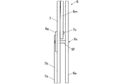
なお、この場合、前述した円形歯車6gの直線歯車7aに対する回動動作と、ホルダー6の回動に伴う棒状部材6mの回動動作とが干渉しないようにするために、例えば図14に示すように、円形歯車6gや直線歯車7aを支持部材7の背面側(裏面側)に設け、棒状部材6mや軸部7cを支持部材7の表面側(すなわちホルダー6が設けられた側)に設けるように構成することが可能である。なお、図14は、回動角度が0°のホルダー6等を図13における左側から見た場合の側面図である。   In this case, for example, as shown in FIG. 14, in order to prevent interference between the turning operation of the circular gear 6 g with respect to the linear gear 7 a and the turning operation of the rod-shaped member 6 m accompanying the rotation of the holder 6. In addition, the circular gear 6g and the linear gear 7a are provided on the back side (back side) of the support member 7, and the rod-like member 6m and the shaft portion 7c are provided on the surface side of the support member 7 (that is, the side on which the holder 6 is provided). It is possible to configure. 14 is a side view of the holder 6 and the like whose rotation angle is 0 ° when viewed from the left side in FIG.

そして、図13に示した状態すなわちホルダー6の回動角度が0°の状態から、上記のようにホルダー6を左回りに90°回動させると、棒状部材6mは、支持部材7上の軸部7cを中心として回動する。そして、図13に示すように(図13の二点鎖線で示した部分参照)、ホルダー6の背面板6aとスライド板6jとの相対的な位置関係は変わらないものとして、ホルダー6が左回りに90°回動して縦向き中央の位置になった状態でのスライド板6j上の軸部6lと支持部材7上の軸部7cとの距離を計算すると、ちょうど棒状部材6mの長さになる。すなわち、このようにホルダー6を左回りに90°回動させても、棒状部材6mによりスライド板6jの軸部6lが押されることはなく、スライド板6jと背面板6aとの相対的な位置関係は変わらない。そのため、第1係止爪6cと第2係止爪6d、6dとの間隔が14インチに保たれた状態のままホルダー6が左回りに90°回動することになる。   Then, when the holder 6 is rotated 90 ° counterclockwise as described above from the state shown in FIG. 13, that is, the rotation angle of the holder 6 is 0 °, the rod-shaped member 6m It rotates around the part 7c. Then, as shown in FIG. 13 (see the portion indicated by the two-dot chain line in FIG. 13), the relative positional relationship between the back plate 6a and the slide plate 6j of the holder 6 remains unchanged, and the holder 6 is turned counterclockwise. When the distance between the shaft portion 6l on the slide plate 6j and the shaft portion 7c on the support member 7 in the state of being rotated 90 ° to the center in the vertical direction is calculated, it is exactly the length of the rod-shaped member 6m. Become. That is, even if the holder 6 is rotated 90 ° counterclockwise in this way, the shaft portion 61 of the slide plate 6j is not pushed by the rod-shaped member 6m, and the relative position between the slide plate 6j and the back plate 6a is not pushed. The relationship does not change. Therefore, the holder 6 is rotated 90 ° counterclockwise while the distance between the first locking claws 6c and the second locking claws 6d, 6d is maintained at 14 inches.

そして、上記のホルダー6の回動角度が90°の状態からさらにホルダー6を左回りに90°(計180°)回動させると、図15に示すように(図15の実線で示した部分参照)、棒状部材6mは、支持部材7上の軸部7cを中心として回動する。そして、この場合も、ホルダー6の背面板6aとスライド板6jとの相対的な位置関係は変わらないものとして、ホルダー6が左回りにさらに90°回動して横向き中央の位置になった状態でのスライド板6j上の軸部6lと支持部材7上の軸部7cとの距離を計算すると、ちょうど棒状部材6mの長さになる。すなわち、この場合も、ホルダー6を左回りにさらに90°回動させても、棒状部材6mによりスライド板6jの軸部6lが押されることはなく、スライド板6jと背面板6aとの相対的な位置関係が変わらないため、第1係止爪6cと第2係止爪6d、6dとの間隔が14インチに保たれた状態のままホルダー6が左回りに90°回動することになる。   Then, when the holder 6 is further rotated counterclockwise by 90 ° (total 180 °) from the state in which the rotation angle of the holder 6 is 90 °, as shown in FIG. 15 (the portion indicated by the solid line in FIG. 15) Reference), the rod-shaped member 6m rotates around the shaft portion 7c on the support member 7. In this case as well, the relative positional relationship between the back plate 6a and the slide plate 6j of the holder 6 is assumed to be unchanged, and the holder 6 is further rotated 90 ° counterclockwise to the horizontal center position. When the distance between the shaft portion 61 on the slide plate 6j and the shaft portion 7c on the support member 7 is calculated, the length of the rod-shaped member 6m is obtained. That is, also in this case, even if the holder 6 is further rotated counterclockwise by 90 °, the shaft portion 6l of the slide plate 6j is not pushed by the rod-shaped member 6m, and the relative relationship between the slide plate 6j and the back plate 6a. Since the positional relationship does not change, the holder 6 rotates 90 ° counterclockwise with the distance between the first locking claw 6c and the second locking claw 6d, 6d maintained at 14 inches. .

すなわち、上記のように構成した場合、ホルダー6に14×17インチのカセッテ型ディテクターDを装填した場合、少なくとも、ホルダー6を回動角度が0°〜180°の範囲で回動させても、ホルダー6の背面板6aと、棒状部材6mに支持されたスライド板6jとの相対的な位置関係は変わらず、第1係止爪6cと第2係止爪6d、6dとの間隔が的確に14インチに維持される。そのため、ホルダー6をその回動角度の範囲内(すなわち0°〜180°)で回動させる状態では、14×17インチのカセッテ型ディテクターDがホルダー6の第1係止爪6cと第2係止爪6d、6dとで的確に挟持されてホルダー6に保持され、ホルダー6で14×17インチのカセッテ型ディテクターDを保持する状態を的確に維持することが可能となる。   That is, when configured as described above, when a 14 × 17 inch cassette-type detector D is loaded in the holder 6, at least even if the holder 6 is rotated in the range of 0 ° to 180 °, The relative positional relationship between the back plate 6a of the holder 6 and the slide plate 6j supported by the rod-shaped member 6m does not change, and the interval between the first locking claws 6c and the second locking claws 6d and 6d is accurately determined. Maintained at 14 inches. Therefore, in the state in which the holder 6 is rotated within the range of the rotation angle (that is, 0 ° to 180 °), the 14 × 17 inch cassette type detector D is connected to the first locking claw 6c and the second engagement claw of the holder 6. It is possible to accurately hold the 14 × 17 inch cassette type detector D with the holder 6 by being accurately held between the pawls 6d and 6d and held by the holder 6.

一方、上記の状態、すなわちホルダー6を左回りに計180°回動させた状態からさらに90°(計270°)回動させた場合(図15の二点鎖線で示した部分参照)、上記と同様に、仮にホルダー6の背面板6aとスライド板6jとの相対的な位置関係は変わらないものとすると、スライド板6j上の軸部6lは図15の6lで示す位置に来ることになるが、点6lと支持部材7上の軸部7cとの距離は、明らかに棒状部材6mの長さよりも短い。そのため、この場合は、スライド板6jの軸部6lが棒状部材6mにより図中右側に押される状態になり、スライド板6jが背面板6aに対して図中右側に移動(スライド)する。 On the other hand, when the holder 6 is further rotated 90 ° (total 270 °) from the state where the holder 6 is rotated counterclockwise by a total of 180 ° (see the portion indicated by the two-dot chain line in FIG. 15), Similarly, assuming that the relative positional relationship between the back plate 6a of the holder 6 and the slide plate 6j does not change, the shaft portion 6l on the slide plate 6j comes to a position indicated by 6l * in FIG. However, the distance between the point 6l * and the shaft portion 7c on the support member 7 is clearly shorter than the length of the rod-shaped member 6m. Therefore, in this case, the shaft portion 6l of the slide plate 6j is pushed to the right side in the drawing by the rod-shaped member 6m, and the slide plate 6j moves (slides) to the right side in the drawing with respect to the back plate 6a.

そして、棒状部材6mの長さ等から背面板6aに対するスライド板6jの相対的な移動距離を算出すると3インチとなり、上記のように14インチであった第1係止爪6cと第2係止爪6d、6dとの間隔が17インチに自動的に(すなわちホルダー6を回動させるだけで)拡がる。そのため、この状態すなわちホルダー6を左回りに計270°回動させた状態で、17×17インチのカセッテ型ディテクターDをホルダー6に的確に装填することが可能となり、また、その状態で、ホルダー6は17×17インチのカセッテ型ディテクターDを的確に保持することが可能となる。   Then, when the relative movement distance of the slide plate 6j with respect to the back plate 6a is calculated from the length of the rod-like member 6m, etc., it becomes 3 inches, and the first locking claws 6c and the second locking claws that were 14 inches as described above. The distance between the claws 6d and 6d is automatically expanded to 17 inches (that is, only by rotating the holder 6). Therefore, in this state, that is, when the holder 6 is rotated 270 ° in the counterclockwise direction, the 17 × 17 inch cassette type detector D can be accurately loaded into the holder 6, and in this state, the holder 6 can accurately hold a 17 × 17 inch cassette type detector D.

なお、ホルダー6は、図12に示した背面板6aやスライド板6j等を有する構成に限らず、上記のようにホルダー6の回動動作にあわせて棒状部材6mにより第1係止爪6cと第2係止爪6d、6dとの間隔を拡げることができる構成であれば、どのような構成でもよい。   Note that the holder 6 is not limited to the configuration having the back plate 6a, the slide plate 6j, and the like shown in FIG. Any configuration may be used as long as the interval between the second locking claws 6d and 6d can be increased.

[カセッテ型ディテクターに照射する放射線の照射野の自動設定等について]
ところで、上記のような撮影台1に装填されたカセッテ型ディテクターDに、放射線照射装置から被写体を介して放射線を照射して撮影を行う場合、被写体である患者の患部や病変部以外の健全な身体の部分に放射線が照射されないようにして、患者の被曝線量が必要以上に増大しないようにするために、通常、コリメーターにより照射野が絞られた状態で放射線が照射される。
[Automatic setting of the radiation field irradiated to the cassette type detector]
By the way, when imaging is performed by irradiating the cassette type detector D loaded on the imaging table 1 as described above with radiation from the radiation irradiation device through the subject, a healthy part other than the affected part or the lesioned part of the patient as the subject is healthy. In order not to irradiate the body part with radiation and to prevent the exposure dose of the patient from increasing more than necessary, radiation is usually irradiated with the irradiation field constricted by a collimator.

そして、従来は、放射線照射装置から、照射される放射線と同じ範囲にハロゲンランプ等から可視光を照射し、放射線技師等がそれを見ながら手動で放射線照射装置の位置や向きを調整して被写体に照射される放射線の位置や照射方向を調整したり、コリメーターを操作して照射野を絞る等して、放射線が患者の患部等を含む適切な範囲に照射されるように調整を行っていた。しかし、この操作を、放射線照射装置自体が自動的に行うように構成すれば、放射線照射装置の利便性を向上させることができる。   Conventionally, the radiation irradiation device irradiates visible light from a halogen lamp or the like in the same range as the irradiated radiation, and a radiographer or the like manually adjusts the position and orientation of the radiation irradiation device while watching the subject. Adjustments are made so that the radiation is applied to the appropriate area including the affected area of the patient, such as by adjusting the position and direction of the radiation applied to the patient, or by operating the collimator to narrow the irradiation field. It was. However, if this operation is performed automatically by the radiation irradiation apparatus itself, the convenience of the radiation irradiation apparatus can be improved.

そこで、従来、例えば米国特許第7806591号明細書では、カセッテ型ディテクターDに反射部材を設けておき、反射部材までの距離を把握することでSID(Source Image receptor Distance)すなわち放射線照射装置の放射線源の焦点(source)とカセッテ型ディテクターDの受像面(image receptor)との距離(Distance)等を自動的に検出する技術が記載されている。なお、カセッテ型ディテクターDの受像面を、前述したカセッテ型ディテクターDの放射線入射面R(図2等参照)としてもよいが、正確には、図示を省略するが、カセッテ型ディテクターDの、放射線検出素子がセンサー基板上に二次元状に配列された面のことである。   Therefore, conventionally, for example, in US Pat. No. 7,806,591, a cassette-type detector D is provided with a reflecting member, and by grasping the distance to the reflecting member, SID (Source Image receptor Distance), that is, the radiation source of the radiation irradiation apparatus Is a technique for automatically detecting the distance between the source of the image and the image receptor of the cassette-type detector D (Distance). The image receiving surface of the cassette type detector D may be the radiation incident surface R (see FIG. 2 and the like) of the cassette type detector D described above, but to be precise, the radiation of the cassette type detector D is omitted. It is a surface on which the detection elements are two-dimensionally arranged on the sensor substrate.

しかし、上記の方法では、上記のように、カセッテ型ディテクターDが撮影台1に装填されてしまうと、放射線照射装置からカセッテ型ディテクターDに設けられた反射部材を検出することができなくなる。   However, in the above method, as described above, when the cassette type detector D is loaded on the imaging stand 1, it becomes impossible to detect the reflecting member provided on the cassette type detector D from the radiation irradiation apparatus.

また、例えば米国特許第7545914号明細書では、放射線照射装置や撮影台1等が設けられた撮影室内にカメラ等を敷設し、撮影室内を撮影する等して、各装置の位置や患者の位置等を把握する技術が記載されている。しかし、この場合、放射線技師や付き添い人など患者以外の人物がいる場合や障害物が存在する場合等に、各装置や患者の位置等を検出できない虞れがあり、また、複雑な画像処理等が必要になるうえ、放射線照射装置から照射される放射線の光軸を推定することが難しく、使用できる放射線照射装置の配置等が限定されてしまうといった問題が生じ得る。   In addition, for example, in US Pat. No. 7,545,914, the position of each device and the position of a patient are obtained by laying a camera or the like in a photographing room provided with a radiation irradiating device or a photographing stand 1 and photographing the photographing room. The technology which grasps etc. is indicated. However, in this case, if there is a person other than the patient, such as a radiologist or an attendant, or if there are obstacles, the position of each device or patient may not be detected, and complicated image processing, etc. In addition, it is difficult to estimate the optical axis of the radiation irradiated from the radiation irradiating apparatus, and there may be a problem that the arrangement of usable radiation irradiating apparatuses is limited.

そこで、本願発明者らは、カメラを放射線照射装置のコリメーターに付設し、そのカメラの画像解析等によってコリメーターの回転方向や照射される放射線の光軸方向等の検出を行うことを提案した(特開2011−92612号公報等参照)。そして、このような技術についてさらに研究を重ねた結果、より正確に放射線照射装置の放射線源の位置やコリメーターの回転方向、照射される放射線の光軸方向等を検出し、それに基づいてコリメーターによる照射野の設定を自動的にかつ的確に行うことが可能な技術を見出すことができた。以下、この技術について説明する。   Therefore, the inventors of the present application have proposed that a camera is attached to a collimator of a radiation irradiating device, and the rotation direction of the collimator, the optical axis direction of irradiated radiation, and the like are detected by image analysis of the camera. (Refer to Unexamined-Japanese-Patent No. 2011-92612 etc.). As a result of further research on such technology, the position of the radiation source of the radiation irradiation device, the rotation direction of the collimator, the optical axis direction of the irradiated radiation, etc. are detected more accurately, and the collimator is based on that We were able to find a technology that can automatically and accurately set the irradiation field by. Hereinafter, this technique will be described.

図18に示すように、放射線照射装置20には、内部に図示しない絞り等が設けられ放射線照射装置20から照射される放射線の照射野を絞るためのコリメーター21が、放射線照射装置20の図示しない放射線源(例えば後述する図23(A)、(B)等に示す放射線源40参照)が内蔵された円筒部22に取り付けられている。なお、図示を省略するが、コリメーター21は、公知の手法を用いて、絞りの開口部(この開口部を通過した放射線のみが放射線照射装置20から被写体等に照射される。)の開き具合を自動的にかつ正確に変えることができるように構成される。   As shown in FIG. 18, the radiation irradiation apparatus 20 is provided with a not-shown diaphragm or the like, and a collimator 21 for narrowing the irradiation field of the radiation irradiated from the radiation irradiation apparatus 20 is illustrated in the radiation irradiation apparatus 20. A non-radiating radiation source (see, for example, the radiation source 40 shown in FIGS. 23A and 23B described later) is attached to the cylindrical portion 22 in which it is built. Although not shown, the collimator 21 uses a known method to open the aperture of the diaphragm (only the radiation that has passed through the aperture is irradiated from the radiation irradiation device 20 to the subject or the like). Is configured to change automatically and accurately.

また、コリメーター21には、画像を撮影するとともに撮影された対象物までの距離を測定可能なデプスカメラ(Depth camera)等の撮影測定手段23が取り付けられる。なお、以下では、撮影測定手段23を、デプスカメラ23として説明するが、撮影測定手段23はデプスカメラで構成される必要はなく、上記のように、画像を撮影するとともに撮影された対象物までの距離を測定することが可能な構成であればよく、特定の構成には限定されない。   Further, the collimator 21 is attached with a photographing measuring means 23 such as a depth camera that can take an image and measure the distance to the photographed object. In the following description, the photographing measurement means 23 will be described as a depth camera 23. However, the photographing measurement means 23 does not have to be configured by a depth camera, and as described above, the image is taken and the object taken is also photographed. Any configuration can be used as long as the distance can be measured, and the distance is not limited to a specific configuration.

なお、コリメーター21とデプスカメラ23は、それぞれ放射線照射装置20の円筒部22やコリメーター21に対して固着されており、放射線照射装置20の放射線源の焦点Fと、デプスカメラ23の撮像中心Oとの相対的な位置関係は変わらないものとし、それらの間の距離r0、および撮像中心Oから放射線照射装置20の放射線源の焦点Fに向かうオフセットベクトルv0は予め分かっているものとする。   The collimator 21 and the depth camera 23 are respectively fixed to the cylindrical portion 22 and the collimator 21 of the radiation irradiation apparatus 20, and the focal point F of the radiation source of the radiation irradiation apparatus 20 and the imaging center of the depth camera 23. Assume that the relative positional relationship with O does not change, and the distance r0 between them and the offset vector v0 from the imaging center O toward the focal point F of the radiation source of the radiation irradiation apparatus 20 are known in advance.

そして、放射線照射装置20が設けられた撮影室の壁面の上方や、撮影台1のスタンド3(図1(A)、(B)参照)の上端部など、放射線照射装置20との間に患者や他の装置等が介在せず、かつ、装置の使用等により位置が変わることがない位置に、マーカーM1、M2、M3が設けられる。そして、マーカーM1〜M3の各中心の実空間上の座標(すなわち緯度や経度や床面からの高さ(或いは標高))が予め測定されて既知であるものとする。なお、マーカーM1〜M3の形状や色彩等は適宜決められる。   The patient is placed between the radiation irradiation apparatus 20 such as the upper side of the wall of the imaging room where the radiation irradiation apparatus 20 is provided and the upper end of the stand 3 of the imaging table 1 (see FIGS. 1A and 1B). Markers M1, M2, and M3 are provided at positions that do not include any other devices or the like and that do not change positions due to use of the devices. Then, it is assumed that the coordinates of the centers of the markers M1 to M3 in the real space (that is, latitude, longitude, height from the floor (or altitude)) are measured in advance and known. Note that the shapes and colors of the markers M1 to M3 are appropriately determined.

以下、上記の構成の下で、放射線照射装置20が自動的に放射線源の焦点Fの位置や放射線の照射方向、撮影台1に装填されたカセッテ型ディテクターDまでの距離(すなわち前述したSID。以下、この距離を距離SIDという。)等を自動的に割り出して、放射線の照射野を自動的にかつ的確に設定する仕方を、図18に基づいて説明する。なお、以下では、放射線照射装置20自体で距離SIDの割り出し処理を含む全ての処理を行うことを前提として説明するが、例えば、放射線照射装置20等から図示しない外部の処理装置にデータ等を送信し、処理装置で距離SIDの割り出し処理等を行うように(すなわち放射線照射装置20や処理装置を有する放射線画像撮影システムとして構成するように)構成することも可能である。   Hereinafter, under the above-described configuration, the radiation irradiation apparatus 20 automatically selects the position of the focal point F of the radiation source, the irradiation direction of the radiation, and the distance to the cassette type detector D loaded on the imaging table 1 (that is, the SID described above). Hereinafter, a method of automatically determining such distance as the distance SID and automatically and accurately setting the radiation field will be described with reference to FIG. In the following description, it is assumed that the radiation irradiation apparatus 20 itself performs all the processes including the distance SID determination process. For example, data or the like is transmitted from the radiation irradiation apparatus 20 or the like to an external processing apparatus (not shown). It is also possible to configure the processing device to perform the distance SID indexing processing or the like (that is, to configure the radiation image capturing system having the radiation irradiation device 20 or the processing device).

まず、デプスカメラ23でマーカーM1〜M3を撮影する。なお、マーカーM1〜M3に色彩が付されている場合には、デプスカメラ23は、マーカーM1〜M3のカラー画像を撮影し、マーカーM1〜M3の画像上の位置を割り出す。また、デプスカメラ23で、マーカーM1〜M3の各中心までの距離r1〜r3を測定して取得する。そして、マーカーM1〜M3の各中心の実空間上の座標は上記のように既知であるから、距離r1〜r3とマーカーM1〜M3の各中心の実空間上の座標から、デプスカメラ23の撮像中心Oの実空間上の座標を割り出す。   First, the markers M1 to M3 are photographed by the depth camera 23. When the markers M1 to M3 are colored, the depth camera 23 captures the color images of the markers M1 to M3 and determines the positions of the markers M1 to M3 on the image. Further, the depth camera 23 measures and acquires the distances r1 to r3 to the centers of the markers M1 to M3. Since the coordinates of the centers of the markers M1 to M3 in the real space are known as described above, the imaging of the depth camera 23 is performed from the coordinates in the real space of the centers of the distances r1 to r3 and the markers M1 to M3. Determine the coordinates of the center O in real space.

続いて、上記の距離SIDを算出するために、放射線照射装置20の放射線源の焦点Fの実空間上の座標を割り出す処理を行う。この場合、上記のようにして割り出したデプスカメラ23の撮像中心Oの実空間上の座標と前述したオフセットベクトルv0だけではなく、デプスカメラ23がどの方向を向いているか(すなわち後述するカメラ方向v1の鉛直角θ1や水平角θ2)や、放射線照射装置20全体が、放射線の照射方向(すなわち後述するX線方向v2)の周りに何度回転しているか(すなわち後述する全体回転角θ3)が分からないと、放射線照射装置20の放射線源の焦点Fの実空間上の座標を割り出すことができない。   Subsequently, in order to calculate the above-described distance SID, a process of determining coordinates in the real space of the focal point F of the radiation source of the radiation irradiation apparatus 20 is performed. In this case, not only the coordinates in the real space of the imaging center O of the depth camera 23 determined as described above and the offset vector v0 described above, but also the direction in which the depth camera 23 faces (that is, the camera direction v1 described later). And the radiation irradiation apparatus 20 as a whole is rotated around the radiation irradiation direction (that is, an X-ray direction v2 described later) (that is, the entire rotation angle θ3 described later). If it is not known, the coordinates in the real space of the focal point F of the radiation source of the radiation irradiation apparatus 20 cannot be determined.

そこで、まず、デプスカメラ23がどの方向を向いているかを割り出す。ここで、3点を通る平面は1つに決まるため、マーカーM1〜M3を通る仮想的な平面S1を実空間上に設定する。一方、デプスカメラ23で撮影されたマーカーM1〜M3の画像における画素位置をそれぞれ割り出し、各画素位置の相対的な位置関係と、各画素位置と画像中心との相対的な位置関係を割り出す。そして、これらの画像上の相対的な位置関係を、上記のようにして実空間上に設定した仮想的な平面S1に当てはめることで、仮想的な平面S1上に、画像中心を当該平面S1上に投影した点P1の実空間上の座標を割り出す。   Therefore, first, which direction the depth camera 23 is facing is determined. Here, since the number of planes passing through the three points is determined as one, a virtual plane S1 passing through the markers M1 to M3 is set in the real space. On the other hand, the pixel positions in the images of the markers M1 to M3 photographed by the depth camera 23 are respectively determined, and the relative positional relationship between the pixel positions and the relative positional relationship between the pixel positions and the image center are determined. Then, by applying the relative positional relationship on these images to the virtual plane S1 set in the real space as described above, the image center is set on the plane S1 on the virtual plane S1. The coordinates of the point P1 projected onto the real space are determined.

なお、デプスカメラ23の撮像中心Oから点P1に向かう方向(すなわち撮像中心Oから点P1に向かうベクトルv1の方向)を、以下、カメラ方向v1という。また、カメラ方向v1は、放射線照射装置20からの放射線の照射方向v2(以下、X線方向v2という。)と平行になるように、予めデプスカメラ23がコリメーター21に取り付けられているものとする。   The direction from the imaging center O of the depth camera 23 toward the point P1 (that is, the direction of the vector v1 from the imaging center O toward the point P1) is hereinafter referred to as a camera direction v1. The depth camera 23 is attached to the collimator 21 in advance so that the camera direction v1 is parallel to the irradiation direction v2 of radiation from the radiation irradiation apparatus 20 (hereinafter referred to as X-ray direction v2). To do.

また、図19に示すように、あるベクトルvを、基準鉛直面(図19ではy−z平面)および基準水平面(図19ではx−y平面)にそれぞれ投影した各ベクトルの、鉛直軸(図19ではz軸)および基準水平軸(図19ではx軸)とのなす角θ1、θ2をそれぞれ当該ベクトルvの鉛直角θ1および水平角θ2という。また、図18に示すように、放射線照射装置20全体が、全体回転面Sr内で基準軸に対して回転している角度θ3を全体回転角θ3という。   Further, as shown in FIG. 19, a vertical axis (see FIG. 19) of each vector v projected onto a reference vertical plane (the yz plane in FIG. 19) and a reference horizontal plane (the xy plane in FIG. 19), respectively. Angles θ1 and θ2 formed by the z axis in FIG. 19 and the reference horizontal axis (x axis in FIG. 19) are referred to as the vertical angle θ1 and the horizontal angle θ2 of the vector v, respectively. As shown in FIG. 18, the angle θ3 at which the entire radiation irradiation apparatus 20 is rotated with respect to the reference axis in the entire rotation surface Sr is referred to as an overall rotation angle θ3.

そして、上記のように点P1の実空間上の座標が分かると、デプスカメラ23の撮像中心Oの実空間上の座標は既に分かっているため、撮像中心Oと点P1とを結ぶベクトルv1(図18参照)すなわちカメラ方向v1が分かる。そのため、図19に示したようにして、カメラ方向v1の鉛直角θ1や水平角θ2を割り出すことができる。   When the coordinates in the real space of the point P1 are known as described above, the coordinates in the real space of the imaging center O of the depth camera 23 are already known, and thus the vector v1 ( That is, the camera direction v1 is known. Therefore, as shown in FIG. 19, the vertical angle θ1 and the horizontal angle θ2 in the camera direction v1 can be determined.

次に、カメラ方向v1を法線とし、3つのマーカーM1〜M3のうち任意の1つのマーカーM(図18の場合はマーカーM3)を通る仮想的な平面S2を実空間上に設定する。そして、画像中心を当該平面S2上に投影した点P2の実空間上の座標を割り出す。そして、点P2の実空間上の座標とマーカーM3の実空間上の座標から全体回転角θ3を算出する。このようにして、放射線照射装置20全体が、全体回転面Sr内で基準軸に対して全体回転角θ3だけ回転していることを把握することができる。   Next, a virtual plane S2 passing through any one of the three markers M1 to M3 (marker M3 in the case of FIG. 18) is set on the real space with the camera direction v1 as a normal line. Then, the coordinates in the real space of the point P2 obtained by projecting the image center onto the plane S2 are determined. Then, the overall rotation angle θ3 is calculated from the coordinates of the point P2 in the real space and the coordinates of the marker M3 in the real space. In this way, it can be understood that the entire radiation irradiation apparatus 20 is rotated by the entire rotation angle θ3 with respect to the reference axis within the entire rotation surface Sr.

前述したオフセットベクトルv0(図18参照)は、カメラ方向v1の鉛直角θ1や水平角θ2や放射線照射装置20全体の全体回転角θ3がいずれも0°の場合のデプスカメラ23の撮像中心Oから放射線照射装置20の放射線源の焦点Fに向かうベクトル(va,vb,vc)として定義されるから、上記のようにして割り出した実際の鉛直角θ1や水平角θ2や全体回転角θ3に基づいてオフセットベクトルv0が実際にどの方向を向いているかを算出する。すなわち、オフセットベクトルv0=(va,vb,vc)の各成分va、vb、vcと上記の鉛直角θ1、水平角θ2、全体回転角θ3から実際のオフセットベクトルv0の各成分va、vb、vcを割り出す。 The above-described offset vector v0 (see FIG. 18) is obtained from the imaging center O of the depth camera 23 when the vertical angle θ1 and horizontal angle θ2 in the camera direction v1 and the overall rotation angle θ3 of the radiation irradiation apparatus 20 are all 0 °. Since it is defined as a vector (va, vb, vc) toward the focal point F of the radiation source of the radiation irradiation apparatus 20, it is based on the actual vertical angle θ1, horizontal angle θ2, and overall rotation angle θ3 determined as described above. The direction in which the offset vector v0 is actually directed is calculated. That is, each component va * , vb * of the actual offset vector v0 from each component va, vb, vc of the offset vector v0 = (va, vb, vc) and the vertical angle θ1, horizontal angle θ2, and overall rotation angle θ3 . , Vc * .

そして、割り出した実際のオフセットベクトルv0と、既に割り出されているデプスカメラ23の撮像中心Oの実空間上の座標とに基づいて、放射線照射装置20の放射線源の焦点Fの実空間上の座標を算出することができる。以上のようにして、まず、放射線照射装置20の放射線源の焦点Fの実空間上の座標が算出される。   Then, based on the calculated actual offset vector v0 and the coordinates in the real space of the imaging center O of the depth camera 23 that have already been calculated, the focal point F of the radiation source of the radiation irradiation apparatus 20 on the real space. Coordinates can be calculated. As described above, first, the coordinates in the real space of the focal point F of the radiation source of the radiation irradiation apparatus 20 are calculated.

なお、オフセットベクトルv0を、デプスカメラ23の撮像中心Oから放射線照射装置20の放射線源の焦点Fに向かうベクトルの単位ベクトル(すなわち長さは1)として定義する場合には、オフセットベクトルv0にデプスカメラ23の撮像中心Oと放射線照射装置20の放射線源の焦点Fとの距離r0をかけて算出されるベクトルが上記の演算に用いられることは言うまでもない。   When the offset vector v0 is defined as a unit vector (that is, the length is 1) of the vector from the imaging center O of the depth camera 23 toward the focal point F of the radiation source of the radiation irradiation apparatus 20, the depth is set to the offset vector v0. Needless to say, a vector calculated by multiplying the distance r0 between the imaging center O of the camera 23 and the focal point F of the radiation source of the radiation irradiating apparatus 20 is used in the above calculation.

一方、前述したように、撮影台1(図1(A)、(B)等参照)では、ブッキー2に装填されたカセッテ型ディテクターDは撮影台1のスタンド3に沿って昇降可能とされており、その場合、カセッテ型ディテクターDは、実空間上の仮想的な平面S(図18参照)上を昇降するものとする。なお、以下、仮想的な平面Sを、カセッテ型ディテクターDの動作平面Sという。上記の距離SIDは、上記のようにして実空間上の座標が割り出された放射線照射装置20の放射線源の焦点Fから、このカセッテ型ディテクターDの動作平面Sまでの距離ということになる。 On the other hand, as described above, in the photographing stand 1 (see FIGS. 1A and 1B and the like), the cassette type detector D loaded in the bucky 2 can be moved up and down along the stand 3 of the photographing stand 1. In this case, the cassette type detector D moves up and down on a virtual plane S D (see FIG. 18) in the real space. Hereinafter, the virtual plane S D, that the operating plane S D of the cassette type detector D. The above distance SID would that distance from the focal point F of the radiation source of the radiation irradiation device 20 as described above coordinates in the real space is indexed until the operation plane S D of the cassette type detector D .

そして、上記のように、X線方向v2、すなわち放射線照射装置20の放射線源の焦点Fからの放射線の照射方向v2は、カメラ方向v1と平行であり、カメラ方向v1は上記のようにデプスカメラ23の撮像中心Oと仮想的な平面S1上の点P1とを結ぶベクトルとして既に算出されている。そのため、上記のようにして実空間上の座標が割り出された放射線照射装置20の放射線源の焦点FからX線方向v2のベクトル(ベクトルの各成分はカメラ方向v1の各成分と同じ。)を延ばし、カセッテ型ディテクターDの動作平面Sとの交点Pを割り出す。そして、放射線照射装置20の放射線源の焦点Fと、上記のようにして割り出したカセッテ型ディテクターDの動作平面S上の点Pとの距離が、結局、求める距離SIDということになる。 As described above, the X-ray direction v2, that is, the irradiation direction v2 of radiation from the focal point F of the radiation source of the radiation irradiation apparatus 20 is parallel to the camera direction v1, and the camera direction v1 is a depth camera as described above. It has already been calculated as a vector connecting the 23 imaging centers O and the point P1 on the virtual plane S1. Therefore, the vector in the X-ray direction v2 from the focal point F of the radiation source of the radiation irradiation apparatus 20 in which the coordinates in the real space have been determined as described above (each component of the vector is the same as each component in the camera direction v1). the extended, determine the intersection point P D in the motion plane S D of the cassette type detector D. Then, the focus F of the radiation source of the radiation irradiation device 20, the distance between the point P D on the operation plane S D of the cassette type detector D calculated as described above, after all, it comes to a distance SID to determine.

以上のようにして、放射線照射装置20の放射線源の焦点Fからカセッテ型ディテクターDの受像面までの距離SIDを、放射線照射装置20が自ら、或いは放射線照射装置20からデータを入手した外部の処理装置が、自動的にかつ的確に算出することが可能となる。   As described above, the distance SID from the focal point F of the radiation source of the radiation irradiation apparatus 20 to the image receiving surface of the cassette-type detector D, the external processing in which the radiation irradiation apparatus 20 obtains data by itself or from the radiation irradiation apparatus 20. The apparatus can automatically and accurately calculate.

上記の距離SIDが算出されれば、放射線照射装置20から照射する放射線が、上記の動作平面S内にカセッテ型ディテクターDに的確に照射され、かつ、カセッテ型ディテクターDからはみ出して放射線が照射されないようにするために、放射線照射装置20から照射する放射線を水平方向や鉛直方向にどの程度の拡がりで照射すればよいかが分かる。すなわち照射すべき放射線の照射野が分かる。なお、この場合、撮影台1に装填されているカセッテ型ディテクターDのサイズや向き、配置(すなわち上記の「横向き上方」や「縦向き中央」、「横向き中央」等)の情報が必要になるため、この情報は放射線照射装置20に放射線技師等が入力したり、或いはコンソール等の外部装置から入力される。 If the distance SID is calculated, the radiation irradiated from the radiation irradiation device 20 is accurately irradiated to the cassette type detector D within the operation plane SD , and is projected from the cassette type detector D and irradiated with radiation. In order to prevent this from happening, it is understood how far the radiation irradiated from the radiation irradiation apparatus 20 should be irradiated in the horizontal direction or the vertical direction. That is, the radiation field to be irradiated is known. In this case, information on the size, orientation, and arrangement of the cassette type detector D loaded in the photographing stand 1 (that is, the above “horizontal upward”, “vertical center”, “lateral center”, etc.) is required. Therefore, this information is input to the radiation irradiation apparatus 20 by a radiation engineer or the like, or input from an external apparatus such as a console.

このようにして、放射線照射装置20は、その情報に基づいて、照射する放射線の水平方向や鉛直方向の照射野を算出することで、コリメーター21内の絞りの開口部の開き具合を調節して照射野を自動的にかつ正確に設定することが可能となる。   In this way, the radiation irradiation apparatus 20 adjusts the degree of opening of the aperture of the diaphragm in the collimator 21 by calculating the horizontal and vertical irradiation fields of the irradiated radiation based on the information. Thus, the irradiation field can be set automatically and accurately.

後は、撮影台1に装填したカセッテ型ディテクターDの床面からの高さ(或いは標高。以下同じ。)の情報を放射線技師等が放射線照射装置20に入力したり、或いは、デプスカメラ23等で撮影した画像に対する画像解析から撮影台1のブッキー2の床面からの高さを割り出したり、或いはブッキー2に上記のマーカーM1〜M3とは別のマーカーを設けておき、デプスカメラ23で撮影した当該マーカーの画像から上記と同様にして撮影台1のブッキー2の床面からの高さを割り出す等して、カセッテ型ディテクターDの床面からの高さを割り出す。   After that, a radiographer or the like inputs information on the height (or altitude; the same applies hereinafter) of the cassette type detector D loaded on the imaging table 1 to the radiation irradiation device 20, or the depth camera 23 or the like. The height from the floor surface of the bucky 2 of the photographing stand 1 is determined from the image analysis of the image taken in step 1, or a marker other than the markers M1 to M3 is provided on the bucky 2 and photographed with the depth camera 23. The height from the floor surface of the cassette type detector D is determined by, for example, determining the height from the floor surface of the bucky 2 of the photographing stand 1 from the image of the marker.

また、放射線照射装置20は、必要に応じて、上記の鉛直角θ1や水平角θ2を変更して放射線の照射方向であるX線方向v2を変えたり、円筒部22や放射線照射装置20自体を回転させて全体回転角θ3を調節して、放射線源の焦点Fから照射した放射線が、上記のようにして割り出した床面からの高さに存在するカセッテ型ディテクターDに的確に照射されるようにする。   Moreover, the radiation irradiation apparatus 20 changes the X-ray direction v2 which is a radiation irradiation direction by changing the vertical angle θ1 and the horizontal angle θ2 as necessary, or the cylindrical portion 22 or the radiation irradiation apparatus 20 itself. By rotating and adjusting the overall rotation angle θ3, the radiation irradiated from the focal point F of the radiation source is accurately irradiated to the cassette type detector D existing at the height from the floor surface determined as described above. To.

放射線照射装置20、或いは放射線照射装置20や処理装置を有する放射線画像撮影システムを以上のように構成することで、放射線照射装置20の放射線源の焦点Fからカセッテ型ディテクターDの受像面までの距離SIDを、放射線照射装置20が自ら、或いは放射線照射装置20からデータを入手した処理装置が、自動的にかつ的確に算出し、それに基づいて、放射線照射装置20が、放射線をカセッテ型ディテクターDに照射し、かつ、カセッテ型ディテクターD以外の部分には照射されないように放射線の照射野を自動的にかつ的確に設定することが可能となる。そのため、放射線照射装置20の利便性を向上させることが可能となる。   The distance from the focal point F of the radiation source of the radiation irradiating device 20 to the image receiving surface of the cassette type detector D is configured as described above by configuring the radiation irradiating device 20 or the radiation image capturing system having the radiation irradiating device 20 and the processing device. The radiation irradiation device 20 itself or the processing device that has obtained data from the radiation irradiation device 20 automatically and accurately calculates the SID, and based on this, the radiation irradiation device 20 sends the radiation to the cassette type detector D. It is possible to automatically and accurately set the radiation field so that irradiation is performed and portions other than the cassette type detector D are not irradiated. Therefore, the convenience of the radiation irradiation apparatus 20 can be improved.

また、放射線の照射野をより精密に設定し、例えば前述したように被写体である患者の患部や病変部を含む必要な範囲にのみ放射線を照射し、それ以外の健全な身体の部分には放射線が照射されないようにするために、上記の技術に加えて、さらに、例えば放射線照射装置20に必要な情報を入力する等して、放射線の照射野をより狭く精密に設定するように構成することも可能である。   Also, set the radiation field more precisely, for example, as described above, irradiate only the necessary area including the affected area or lesion of the patient as the subject, and apply radiation to other healthy body parts. In addition to the above-described technique, for example, necessary information is input to the radiation irradiating apparatus 20 so that the radiation field is set narrower and more precisely. Is also possible.

この場合、撮影の際、被写体である患者は、必ず放射線照射装置20の放射線源の焦点Fとカセッテ型ディテクターDとの間に入る。そのため、例えば、撮影時にデプスカメラ23で距離を測定して、カセッテ型ディテクターDよりも放射線照射装置20側に近い位置(すなわち距離SIDよりも短い距離)に物体が検出された場合には、それを被写体(すなわち患者)であると認識することが可能となる。その際、被写体である患者は、必ず撮影台1の近傍に存在する。そして、上記のようにカセッテ型ディテクターDの動作平面S(図18参照)は既知であるため、被写体の存在する空間は、カセッテ型ディテクターDの動作平面S或いはそれから割り出される撮影台1の近傍でかつ放射線照射装置20側と仮定することができる。カセッテ型ディテクターDや撮影台1の放射線照射装置20側であるか否かはデプスカメラ23で測定することができるため、容易に割り出すことができる。また、撮影時には放射線は必ず被写体に向けて照射される。そのため、これらの情報を用いることで、放射線照射装置20は、被写体を撮影するのに必要十分な範囲にのみ放射線を照射するように放射線の照射野を自動的にかつ適切に設定することも可能となる。 In this case, the patient who is the subject always enters between the focal point F of the radiation source of the radiation irradiation apparatus 20 and the cassette type detector D at the time of imaging. Therefore, for example, when the distance is measured by the depth camera 23 at the time of photographing and an object is detected at a position closer to the radiation irradiation device 20 side than the cassette type detector D (that is, a distance shorter than the distance SID), Can be recognized as a subject (that is, a patient). At that time, the patient as a subject always exists in the vicinity of the imaging table 1. Since the operation plane S D (see FIG. 18) of the cassette type detector D is known as described above, the space in which the subject exists is the operation plane S D of the cassette type detector D or the imaging table 1 calculated therefrom. Near the radiation irradiation device 20 side. Since it can be measured with the depth camera 23 whether it is the cassette type detector D or the radiation irradiation apparatus 20 side of the imaging stand 1, it can be calculated easily. Also, at the time of photographing, radiation is always directed toward the subject. Therefore, by using these pieces of information, the radiation irradiating apparatus 20 can automatically and appropriately set the radiation irradiation field so that the radiation is irradiated only in a range necessary and sufficient for photographing the subject. It becomes.

そして、患者の身体における患部や病変部の位置がどの位置であるか等の情報が入手できれば、放射線照射装置20は、患部等を含む必要な範囲にのみ放射線を照射するように放射線の照射野をさらに限定するように構成することも可能となる。   Then, if information such as the position of the affected part or lesion part in the patient's body is available, the radiation irradiating apparatus 20 irradiates the radiation field so as to irradiate only the necessary range including the affected part. It is also possible to configure so as to further limit the above.

なお、放射線照射装置20は、上記のように放射線がカセッテ型ディテクターDのみに照射されるように放射線の照射野を設定し、その後、放射線技師等がマニュアル操作で、被写体である患者の患部や病変部を含む必要な範囲にのみ放射線を照射するように放射線の照射野を狭める等の操作を行うように構成することも可能である。   The radiation irradiation device 20 sets the radiation field so that the radiation is irradiated only to the cassette type detector D as described above, and then the radiation technician or the like manually operates the affected area of the patient as the subject. It is also possible to perform an operation such as narrowing the radiation field so that the radiation is irradiated only to a necessary range including the lesioned part.

また、上記の例では、カセッテ型ディテクターDが図1(A)、(B)等に示した、いわゆる立位撮影台1に装填され、カセッテ型ディテクターDの受像面が略水平方向を向く状態でカセッテ型ディテクターDがブッキー2の昇降にあわせて昇降する場合について説明した。しかし、カセッテ型ディテクターDがいわゆる臥位撮影台に装填される場合のように、カセッテ型ディテクターDの受像面が上方を向く状態で、カセッテ型ディテクターDが昇降するように構成される場合もある。   In the above example, the cassette type detector D is loaded on the so-called standing imaging stand 1 shown in FIGS. 1A and 1B, and the image receiving surface of the cassette type detector D faces in a substantially horizontal direction. The case where the cassette type detector D moves up and down in accordance with the lifting and lowering of the bucky 2 has been described. However, there are cases where the cassette type detector D is moved up and down with the image receiving surface of the cassette type detector D facing upward, as in the case where the cassette type detector D is loaded on a so-called upright photographing stand. .

このような場合には、カセッテ型ディテクターDを装填するブッキーや、臥位撮影台の天板(すなわち被写体が上面側に横臥する板)等の、カセッテ型ディテクターDとともに昇降し、かつ、放射線照射装置20のデプスカメラ23で撮影し得る部分に、上記のマーカーM1〜M3とは別のマーカーを設けておき、デプスカメラ23で撮影した当該マーカーの画像から上記と同様にして臥位撮影台のブッキーや天板の床面からの高さを割り出す等して、カセッテ型ディテクターDの床面からの高さを割り出したり、上記の距離SIDを算出したりするように構成することが可能である。   In such a case, the cassette-type detector D can be lifted and lowered together with the cassette-type detector D, such as a bucky for loading the cassette-type detector D, or a top plate (that is, a plate on which the subject lies on the upper surface side). A marker other than the above-described markers M1 to M3 is provided in a portion of the apparatus 20 that can be photographed by the depth camera 23, and the image of the marker photographed by the depth camera 23 is used in the same manner as described above. For example, the height of the cassette type detector D from the floor surface can be calculated by calculating the height of the bucky or the top plate from the floor surface, or the distance SID can be calculated. .

[被写体の被曝線量を正確に算出する手法について]
一方、上記の放射線照射装置20に関連して、放射線照射装置20には、放射線照射装置20から照射された放射線の面積線量(Dose Area Product:DAP)を計測するためのDAPメーターが取り付けられる場合が多い。しかし、このDAPメーターでは、放射線照射装置20から照射された放射線の面積線量が計測されるだけであり、DAPメーターを用いるだけでは、被写体である患者に照射された面積線量がどの程度であるか、すなわち被写体の被曝線量を正確に求めることができない。
[How to accurately calculate the exposure dose of a subject]
On the other hand, in relation to the radiation irradiation apparatus 20, a DAP meter for measuring an area dose (Dose Area Product: DAP) of radiation irradiated from the radiation irradiation apparatus 20 is attached to the radiation irradiation apparatus 20. There are many. However, with this DAP meter, only the area dose of radiation emitted from the radiation irradiation device 20 is measured, and to what extent the area dose irradiated to the patient as a subject is only by using the DAP meter. That is, the exposure dose of the subject cannot be determined accurately.

この場合、例えば、放射線照射装置20から照射する放射線の照射野を絞り、例えば図20に示すように、照射された放射線が被写体Hを介して全てカセッテ型ディテクターDに入射するように放射線を照射すれば(すなわち照射した放射線がカセッテ型ディテクターD外に漏れないように放射線を照射すれば)、撮影された画像を解析して、被写体Hが撮影されている領域Raの面積と、被写体Hが撮影されていない領域Rbの面積を算出し、DAPメーターが計測した面積線量をRa/(Ra+Rb)倍することで、被写体Hである患者の実際の被曝線量を算出することができる。   In this case, for example, the irradiation field of the radiation irradiated from the radiation irradiation device 20 is narrowed down, and the irradiation is performed so that all the irradiated radiation enters the cassette type detector D through the subject H as shown in FIG. If this is done (that is, if radiation is irradiated so that the irradiated radiation does not leak outside the cassette type detector D), the captured image is analyzed, and the area Ra of the subject H being photographed and the subject H By calculating the area of the region Rb that has not been imaged and multiplying the area dose measured by the DAP meter by Ra / (Ra + Rb), the actual exposure dose of the patient who is the subject H can be calculated.

しかし、実際の撮影においては、上記のように、放射線照射装置20から照射される放射線の照射野がカセッテ型ディテクターD内に収まるように放射線が照射されるとは限らないため、どのような撮影においても、被写体Hの実際の被曝線量を正確に算出することができる手法の開発が求められている。本願発明者は、このような状況に鑑み、被写体Hの被曝線量を正確に求める手法等について研究を重ねた結果、以下のように構成することで、それを実現することが可能であることを見出した。   However, in actual imaging, as described above, radiation is not always applied so that the radiation field irradiated from the radiation irradiation device 20 is within the cassette type detector D. However, there is a need for the development of a method that can accurately calculate the actual exposure dose of the subject H. In view of such a situation, the inventor of the present application has conducted research on a method for accurately obtaining the exposure dose of the subject H, and as a result, it can be realized by configuring as follows. I found it.

例えば、上記の撮影台1にカセッテ型ディテクターDを装填して撮影を行う場合、図21に示すように、放射線照射装置20と撮影台1との間に、放射線照射装置20から照射された放射線を検出する放射線センサー30を設けるように構成する。その際、放射線センサー30は、例えば支持板31に取り付けられ、支持板31が図示しない移動装置により移動される等して、実空間上の所定の仮想的な平面S上を2次元的に移動することができるように構成される。 For example, when the cassette type detector D is loaded on the imaging table 1 and imaging is performed, the radiation irradiated from the radiation irradiation device 20 between the radiation irradiation device 20 and the imaging table 1 as shown in FIG. The radiation sensor 30 for detecting the above is provided. At that time, the radiation sensor 30, for example, attached to the support plate 31, and the like are moved by the moving device in which the support plate 31 (not shown), a predetermined virtual on a plane S S in the real space two dimensionally It is configured to be able to move.

なお、放射線センサー30と放射線照射装置20の放射線源の焦点Fとの距離rsは予め分かっているものとする。また、放射線センサー30を、例えば上下方向に(すなわち1次元的に)のみ移動することができるように構成し、下記のように放射線センサー30が検出した、放射線照射装置20から照射される放射線の上下方向の範囲と、放射線照射装置20のコリメーター21で設定される照射野の上下方向と左右方向の比から、放射線照射装置20から照射される放射線の左右方向の範囲を推定するように構成することも可能である。その際、放射線センサー30を取り付ける支持板31としては、例えば、特開2013−154146号公報等に記載されている長尺撮影用の覆い板ユニットの覆い板(同公報における覆い板ユニット60の覆い板61参照)を利用することが可能である。さらに、放射線センサー30を複数設けるように構成することも可能である。   It is assumed that the distance rs between the radiation sensor 30 and the focal point F of the radiation source of the radiation irradiation apparatus 20 is known in advance. Further, the radiation sensor 30 is configured to be movable only in the vertical direction (that is, one-dimensionally), for example, and the radiation irradiated from the radiation irradiation apparatus 20 detected by the radiation sensor 30 as described below is used. The configuration is such that the range in the horizontal direction of the radiation irradiated from the radiation irradiation device 20 is estimated from the range in the vertical direction and the ratio between the vertical direction and the horizontal direction of the irradiation field set by the collimator 21 of the radiation irradiation device 20. It is also possible to do. At this time, as the support plate 31 to which the radiation sensor 30 is attached, for example, a cover plate of a cover plate unit for long photographing described in JP 2013-154146 A (the cover of the cover plate unit 60 in the same publication). It is possible to use a plate 61). Further, it is possible to provide a plurality of radiation sensors 30.

そして、例えば、放射線センサー30や支持板31等を放射線照射装置20と撮影台1との間から退避させた状態で、撮影時或いは撮影前に、放射線照射装置20の放射線源の焦点Fと撮影台1に装填されたカセッテ型ディテクターDとの距離SIDを測定する。その際、上記の測定手法を用いることも可能であり、他の方法で距離SIDを測定してもよい。そして、撮影時には、上記のようにして放射線照射装置20が自動的に調整したり、或いは従来のように放射線技師等が放射線照射装置20から照射される可視光を見ながら手動で調整する等して、被写体Hである患者に放射線が適切に照射されるように、放射線照射装置20のコリメーター21の絞りを操作して照射野を調整する。   Then, for example, in a state where the radiation sensor 30 and the support plate 31 are retracted from between the radiation irradiation apparatus 20 and the imaging table 1, the focal point F of the radiation source of the radiation irradiation apparatus 20 and imaging before or during imaging. The distance SID with the cassette type detector D loaded on the table 1 is measured. At that time, it is also possible to use the measurement method described above, and the distance SID may be measured by another method. At the time of imaging, the radiation irradiating apparatus 20 automatically adjusts as described above, or a radiographer or the like manually adjusts while observing the visible light emitted from the radiation irradiating apparatus 20 as in the past. The irradiation field is adjusted by operating the aperture of the collimator 21 of the radiation irradiation apparatus 20 so that the patient who is the subject H is appropriately irradiated with radiation.

そして、その状態で、一旦、被写体Hである患者を撮影台1の前から退避させ、放射線照射装置20から放射線を照射させ(なお、照射する放射線は放射線センサー30が検出できる程度の線量であればよい。)、放射線センサー30を2次元状或いは1次元状に移動させることで、放射線照射装置20から照射される放射線の上下方向および左右方向の範囲を計測する。そして、一方、実際に被写体Hに放射線を照射して撮影を行う時点で、デプスカメラ23や他の撮像手段で被写体Hを含む画像を撮影する。   Then, in this state, the patient who is the subject H is temporarily withdrawn from the front of the imaging table 1 and irradiated with radiation from the radiation irradiation device 20 (the radiation to be irradiated should be a dose that can be detected by the radiation sensor 30). The radiation sensor 30 is moved two-dimensionally or one-dimensionally to measure the vertical and horizontal ranges of the radiation emitted from the radiation irradiation device 20. On the other hand, at the point of time when the subject H is actually irradiated with radiation, an image including the subject H is taken with the depth camera 23 or other imaging means.

上記のように、放射線照射装置20の放射線源の焦点Fと撮影台1に装填されたカセッテ型ディテクターDとの距離SIDは測定されて分かっており、放射線センサー30と放射線照射装置20の放射線源の焦点Fとの距離rsも既知であるから、それらと、上記のようにして計測された照射される放射線の範囲に基づいて、図22に示すように、撮影された画像中に、放射線照射装置20の放射線源の焦点Fからの距離SID(すなわちカセッテ型ディテクターDが存在する距離SID)における放射線の範囲Rallを特定することができる。   As described above, the distance SID between the focal point F of the radiation source of the radiation irradiation apparatus 20 and the cassette type detector D loaded on the imaging table 1 is measured and known, and the radiation source of the radiation sensor 30 and the radiation irradiation apparatus 20 is known. Since the distance rs from the focal point F is also known, based on these and the range of the irradiated radiation measured as described above, as shown in FIG. The radiation range Rall at the distance SID from the focal point F of the radiation source of the apparatus 20 (that is, the distance SID where the cassette type detector D exists) can be specified.

そして、画像を解析することで、被写体Hが撮影されている領域Rcの面積と、被写体Hが撮影されていない領域Rdの面積を算出することができるため、DAPメーターが計測した面積線量をRc/(Rc+Rd)倍することで、被写体Hである患者の実際の被曝線量を正確に算出することが可能となる。   Then, by analyzing the image, the area of the region Rc where the subject H is photographed and the area of the region Rd where the subject H is not photographed can be calculated, so the area dose measured by the DAP meter can be calculated as Rc. By multiplying by / (Rc + Rd), it becomes possible to accurately calculate the actual exposure dose of the patient who is the subject H.

このように、本願発明者が新たに見出した上記の構成(図21参照)を用いれば、被写体である患者の実際の被曝線量(すなわち患者に実際に照射された面積線量)を正確に算出することが可能となる。そして、患者の実際の被曝線量を正確に把握して、患者に必要以上の面積線量の放射線が照射されないようにすることで、患者の被曝線量の低減を図ることも可能となる。   As described above, when the above-described configuration newly found by the inventor of the present application (see FIG. 21) is used, the actual exposure dose of the patient as the subject (that is, the area dose actually irradiated to the patient) is accurately calculated. It becomes possible. And it becomes possible to aim at reduction of a patient's exposure dose by grasping | ascertaining the patient's actual exposure dose correctly and preventing the patient from being irradiated with an area dose of radiation more than necessary.

[放射線源を小焦点化しつつ高出力化することについて]
ところで、前述したように、撮影台1に装填されたパネルD(すなわちFPDカセッテやCRカセッテのカセッテ型ディテクターD)に放射線を照射する放射線照射装置20(例えば前述した図18等参照)内には、放射線を発生させる放射線源40等が設けられている。そして、放射線源40は、例えば図23(A)、(B)に示すように、回転陽極41の傾斜面41aの一部の領域すなわち焦点Fの部分に、その下方に設けられた電子銃42から電子ビームBを照射することで、焦点FでX線等の放射線を発生させるように構成される。
[About increasing the output while reducing the focus of the radiation source]
By the way, as described above, in the radiation irradiation apparatus 20 (for example, see FIG. 18 described above) that irradiates the panel D (that is, the cassette type detector D of the FPD cassette or the CR cassette) mounted on the photographing stand 1. A radiation source 40 for generating radiation is provided. The radiation source 40 is, for example, as shown in FIGS. 23A and 23B, an electron gun 42 provided below a partial region of the inclined surface 41a of the rotating anode 41, that is, the focal point F. By irradiating with an electron beam B, radiation such as X-rays is generated at the focal point F.

なお、図23(A)は、放射線源40の回転陽極41等を被写体側から見た図であり、図23(B)は、図23(A)の回転陽極41等を向かって左側から見た図である。また、以下の各図においても同様であるが、図23(A)、(B)では、焦点Fの形状等を見やすくするために、回転陽極41等の大きさに比べて焦点Fが非常に大きく記載されている。そのため、例えば図23(B)では、電子レンズ43で電子ビームBがほとんど絞られていないように記載されているが、実際には、例えば焦点Fの径が数百μmの大きさになるように絞られる。さらに、改めて説明するまでもないが、電子ビームBが回転陽極41の傾斜面41aの焦点Fの位置で反射されるわけではなく、電子ビームBが照射された焦点Fが放射線の発光源となる。そのため、放射線は焦点Fから四方に放射されるため、それを前述したコリメーターでコリメートする等して、例えば図23(A)に示した場合には図の手前側に向かって(図23(B)し示した場合には図の右側に向かって)放射線が照射されるように構成される。   23A is a view of the rotating anode 41 and the like of the radiation source 40 viewed from the subject side, and FIG. 23B is a view of the rotating anode 41 and the like of FIG. 23A viewed from the left side. It is a figure. The same applies to the following drawings, but in FIGS. 23A and 23B, the focus F is much larger than the size of the rotary anode 41 and the like in order to make the shape of the focus F easier to see. Largely described. Therefore, for example, in FIG. 23B, it is described that the electron beam B is hardly focused by the electron lens 43, but in practice, for example, the diameter of the focal point F is several hundred μm. It is narrowed down to. Further, it is needless to say that the electron beam B is not reflected at the position of the focal point F of the inclined surface 41a of the rotating anode 41, and the focal point F irradiated with the electron beam B becomes a radiation emission source. . Therefore, since radiation is radiated from the focal point F in all directions, it is collimated by the collimator described above, for example, in the case shown in FIG. 23A, toward the front side of the figure (FIG. 23 ( B) When shown, it is configured to irradiate radiation (towards the right side of the figure).

一方、焦点Fの拡がりが大きいと、放射線源40から被写体を介してパネルDに放射線を照射して撮影された画像がぼやける。そのため、放射線源40には、焦点Fの拡がりを小さくすること、すなわち小焦点化が求められる。   On the other hand, when the spread of the focus F is large, an image captured by irradiating the panel D with radiation from the radiation source 40 through the subject is blurred. Therefore, the radiation source 40 is required to reduce the spread of the focal point F, that is, to reduce the focal point.

しかし、焦点Fを小さくし過ぎると、図24に示すように、回転している回転陽極41の傾斜面41aの一部に電子ビームBが照射される状態になり、その部分だけが線状に傷んでしまい(図24の線L参照)、回転陽極41の寿命が短くなる。そのため、小焦点化する場合には電子ビームBのエネルギーを小さくしなければならず、放射線源40から照射される放射線の出力を低下せざるを得ない。また、放射線源40を高出力化したい場合には、上記のように回転陽極41の傾斜面41aを損傷させないようにするために、焦点Fを拡げざるを得ない。すなわち大焦点化しなければならない。   However, if the focal point F is too small, as shown in FIG. 24, a part of the inclined surface 41a of the rotating rotating anode 41 is irradiated with the electron beam B, and only that part is linear. It will be damaged (see line L in FIG. 24), and the life of the rotating anode 41 will be shortened. Therefore, when the focal point is reduced, the energy of the electron beam B must be reduced, and the output of radiation irradiated from the radiation source 40 must be reduced. Further, when it is desired to increase the output of the radiation source 40, the focal point F must be expanded in order not to damage the inclined surface 41a of the rotating anode 41 as described above. In other words, the focus must be increased.

また、電子銃42から照射された電子ビームBを絞る電子レンズ43は、電子ビームBのエネルギーに依存する収差の影響で電子ビームBを絞る性能にも限界がある。そのため、現状の放射線源40では、低出力だが小焦点化して放射線を照射するか、或いは大焦点化するが高出力で放射線を照射するかを選択するように構成されているものが多い。   Further, the electron lens 43 that narrows the electron beam B irradiated from the electron gun 42 has a limit in the ability to narrow the electron beam B due to the influence of aberration depending on the energy of the electron beam B. For this reason, many of the current radiation sources 40 are configured to select whether to irradiate radiation with a low output but with a small focus, or to increase radiation with a high output but with high output.

また、図25(A)に示すように、仮に回転陽極41の側面41bに傾斜を設けず(すなわち側面41bの法線が水平方向を向くようにして)、この側面41bに、図23(B)に示した電子ビームBと同じ径の電子ビームBを照射すると、図25(B)に示すように、焦点Fの縦方向の見かけの径が大きくなるのに対して、図23(B)に示したように、回転陽極41、電子ビームBが照射される面を傾斜面41aとし、そこに電子ビームBを照射することで、図23(A)に示したように、少なくとも焦点Fの縦方向の径を見かけ上小さくすることができる。なお、図25(A)における焦点Fの実際の径Δと、図23(B)における焦点Fの実際の径Δは同じである。   Further, as shown in FIG. 25 (A), the side surface 41b of the rotating anode 41 is not inclined (that is, the normal of the side surface 41b faces the horizontal direction). When the electron beam B having the same diameter as the electron beam B shown in FIG. 25 is irradiated, the apparent diameter in the vertical direction of the focal point F increases as shown in FIG. 25B, whereas FIG. As shown in FIG. 23, the surface to which the rotating anode 41 and the electron beam B are irradiated is the inclined surface 41a, and the electron beam B is irradiated to the inclined surface 41a. The diameter in the vertical direction can be apparently reduced. Note that the actual diameter Δ of the focal point F in FIG. 25A is the same as the actual diameter Δ of the focal point F in FIG.

現状の放射線源40では、このようにして、放射線を高出力で照射する場合でも、少なくとも焦点Fの縦方向については小焦点化を図る工夫がなされている。しかし、焦点Fの横方向については、放射線を高出力で照射する場合に小焦点化することができず、やはり現状では、低出力かつ小焦点か、大焦点で高出力かを選択しなければならない状況にある。   In the present radiation source 40, in this way, even when radiation is irradiated at a high output, a device for reducing the focal point at least in the longitudinal direction of the focal point F is devised. However, in the lateral direction of the focal point F, when the radiation is irradiated at a high output, the focal point cannot be reduced, and at present, it is necessary to select a low output and a small focal point, or a large focal point and a high output. There is no situation.

本願発明者は、このような状況に鑑み、放射線源を小焦点化しつつ、かつ高出力化する方法や構成等について研究を重ねた結果、以下のように構成することで、それを実現することが可能であることを見出した。   In view of this situation, the inventor of the present application has conducted research on methods and configurations for increasing the output while reducing the focus of the radiation source, and as a result, the following configuration is realized. Found that is possible.

すなわち、従来の放射線源40、すなわち現状の放射線源40では、図23(A)に示したように、放射線源40の回転陽極41等を被写体側から見た場合、回転陽極41の左右方向の中央の位置に電子ビームBを照射して焦点Fを形成したが、本願発明者が新たに見出した構成の放射線源40では、焦点Fを形成する位置を、図26(A)に示すように、回転陽極41の左右方向の左端(または右端。以下同じ。)の位置に変える。そして、図23(A)に示した従来の放射線源のように回転陽極41に傾斜面41aを設ける代わりに、図26(A)に示すように、電子ビームBが照射される回転陽極41の面を傾斜のない側面41bとする。 That is, in the conventional radiation source 40, that is, the current radiation source 40, when the rotating anode 41 and the like of the radiation source 40 are viewed from the subject side as shown in FIG. was formed focus F by irradiating an electron beam B in the middle position, the present inventor radiation source of the newly discovered configuration 40 *, the position for forming a focal point F, so that shown in Fig. 26 (a) Then, the position is changed to the position of the left end (or right end, the same applies hereinafter) of the rotating anode 41 in the left-right direction. Then, instead of providing the inclined surface 41a on the rotating anode 41 as in the conventional radiation source shown in FIG. 23 (A), the rotating anode 41 irradiated with the electron beam B as shown in FIG. The surface is defined as a side surface 41b having no inclination.

なお、図26(A)の回転陽極41等を向かって左側から見ると、図26(B)に示すような状態になり、図25(B)と似た状態になる。しかし、図25(B)の場合は、回転陽極41の焦点Fから放射線が手前側に照射されるのに対して、図26(B)の場合は向かって右側に照射される。また、図25(A)の場合は回転陽極41の焦点Fから放射線が向かって右側に照射されるのに対して、図26(A)の場合は回転陽極41の焦点Fから放射線が手前側に照射される。   Note that when the rotary anode 41 and the like in FIG. 26A are viewed from the left side, the state is as shown in FIG. 26B, which is similar to FIG. However, in the case of FIG. 25B, radiation is emitted from the focal point F of the rotating anode 41 to the near side, whereas in the case of FIG. Further, in the case of FIG. 25A, radiation is irradiated to the right side from the focal point F of the rotating anode 41, whereas in FIG. 26A, the radiation is on the near side from the focal point F of the rotating anode 41. Is irradiated.

そして、図26(A)に示したように、放射線が照射される被写体側から見ると、放射線源40の回転陽極41の焦点Fが縦長に細長く見える状態になり、焦点Fの横方向について小焦点化することができる。しかも、図26(B)に示したように、焦点F自体の拡がりは大きいため、回転陽極41に照射する電子ビームBのエネルギーを大きくすることが可能となる。そのため、上記のように構成することで、放射線源40を、焦点Fの横方向について小焦点化しつつ、かつ、大出力化の放射線源とすることが可能となる。 Then, as shown in FIG. 26 (A), when viewed from the subject side irradiated with radiation, the focal point F of the rotary anode 41 of the radiation source 40 * appears to be elongated in the vertical direction. Small focus can be achieved. In addition, as shown in FIG. 26B, since the focal point F itself has a large spread, the energy of the electron beam B applied to the rotating anode 41 can be increased. Therefore, by configuring as described above, it is possible to make the radiation source 40 * a radiation source with a large output while reducing the focal point in the lateral direction of the focal point F.

つまり、簡単に言えば、本願発明者が新たに見出した構成の放射線源40では、図26(B)に示したように、回転陽極41の側面41bの比較的広い範囲に電子銃42から大きなエネルギーの電子ビームBを照射して大出力化するが、図25(B)に示したようにそのような焦点Fを正面から見る方向に放射線を照射するのではなく、図26(A)に示したように上記の焦点Fを横から見るような方向に放射線を照射するように構成する。そして、このように構成することで、焦点Fの横方向の径を見かけ上小さくして、焦点Fの横方向について小焦点化する。このようにして、本願発明者が新たに見出した構成の放射線源40では、焦点Fの横方向について小焦点化しつつ、かつ、大出力化するようになっている。 That is, simply speaking, in the radiation source 40 * of the configuration newly found by the inventor of the present application, as shown in FIG. 26 (B), the electron gun 42 is disposed within a relatively wide range of the side surface 41b of the rotating anode 41. Although a large energy electron beam B is irradiated to increase the output, as shown in FIG. 25B, radiation is not irradiated in such a direction that the focal point F is viewed from the front. As shown in FIG. 4, the radiation is irradiated in such a direction that the focal point F is viewed from the side. And by comprising in this way, the diameter of the horizontal direction of the focus F is apparently made small, and a small focus is made about the horizontal direction of the focus F. In this way, the radiation source 40 * of the configuration newly found by the inventor of the present application is designed to reduce the focal point in the lateral direction of the focal point F and increase the output.

なお、放射線源40の回転陽極41の側面41bは、回転陽極41の上面や下面に対して垂直である必要はなく、多少傾斜を有していてもよい。また、図26(A)では、回転陽極41の側面41bの真横から電子ビームBを照射する場合を示したが、上方や下方から側面41bに電子ビームBを照射するように構成することも可能である。 Note that the side surface 41b of the rotary anode 41 of the radiation source 40 * does not have to be perpendicular to the upper and lower surfaces of the rotary anode 41, and may have a slight inclination. FIG. 26A shows the case where the electron beam B is irradiated from the side of the side surface 41b of the rotary anode 41. However, the side surface 41b can be irradiated from the upper side or the lower side. It is.

また、図27に示すように、回転陽極41の回転軸を傾斜させて、回転陽極41の傾斜面41aが、例えば左端(或いは右端)の位置で垂直方向或いはそれに近い方向を向くようにして(すなわち傾斜面41aのその位置での法線が水平方向或いはそれに近い方向を向くようにして)、その位置に電子ビームBを照射するように構成することも可能である。なお、図27においても、放射線は回転陽極41の焦点Fから図の手前側に照射される。   In addition, as shown in FIG. 27, the rotation axis of the rotary anode 41 is inclined so that the inclined surface 41a of the rotary anode 41 faces the vertical direction or a direction close thereto (for example, at the left end (or right end) position). That is, it is possible to irradiate the position with the electron beam B (with the normal line at the position of the inclined surface 41a facing the horizontal direction or a direction close thereto). In FIG. 27 as well, radiation is emitted from the focal point F of the rotating anode 41 toward the front side of the figure.

いずれにせよ、本願発明者が新たに見出した構成の放射線源40では、回転陽極41等を被写体側から見た場合、従来の放射線源では回転陽極41の左右方向の中央の位置に電子ビームBを照射して形成していた焦点Fの位置を、回転陽極41の左右方向の左端または右端の位置に変え、回転陽極41の左右方向の左端または右端の位置に電子ビームBを照射して焦点Fを形成する(図26(A)や図27参照)。そして、このように構成することで、焦点Fの横方向の径を見かけ上小さくして、焦点Fの横方向について小焦点化する。そして、その際、大きなエネルギーの電子ビームBを照射しても焦点Fの横方向の見かけ上の径は小さいままであるから、焦点Fの横方向について小焦点化しつつ、かつ、大出力化することが可能となる。 In any case, in the radiation source 40 * of the configuration newly found by the inventor of the present application, when the rotary anode 41 and the like are viewed from the subject side, the electron beam is positioned at the center in the left-right direction of the rotary anode 41 in the conventional radiation source. The position of the focal point F formed by irradiating B is changed to the left or right end position of the rotating anode 41 in the left-right direction, and the electron beam B is irradiated to the left end or right end position of the rotating anode 41 in the left-right direction. A focal point F is formed (see FIG. 26A and FIG. 27). And by comprising in this way, the diameter of the horizontal direction of the focus F is apparently made small, and a small focus is made about the horizontal direction of the focus F. At that time, the apparent diameter in the lateral direction of the focal point F remains small even when the electron beam B having a large energy is irradiated, so that the focal point F has a small focal point and a large output. It becomes possible.

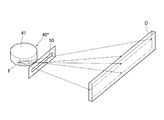
一方、上記のように構成すると、回転陽極41の焦点Fの横方向の見かけ上の径は小さくなるが、縦方向の径は見かけ上も小さくならない。そのため、例えば図28に示すように、放射線源40の回転陽極41の出力側にスリット50を設けて、回転陽極41から照射される放射線が縦方向に拡がることを規制する。そして、この状態で、図示しない被写体を介して撮影装置Dに放射線を照射する。なお、図28では、回転陽極41上の焦点Fが線光源として線状に記載されている。 On the other hand, when configured as described above, the apparent diameter in the horizontal direction of the focal point F of the rotary anode 41 is reduced, but the vertical diameter is not apparently reduced. Therefore, for example, as shown in FIG. 28, a slit 50 is provided on the output side of the rotary anode 41 of the radiation source 40 * to restrict the radiation irradiated from the rotary anode 41 from spreading in the vertical direction. In this state, the imaging apparatus D is irradiated with radiation through a subject (not shown). In FIG. 28, the focal point F on the rotary anode 41 is described in a linear form as a line light source.

そして、図28に示した状態で、放射線源40から照射する放射線を左右方向に振るように構成することで、放射線源40を用いていわゆるラインスキャン型の放射線照射装置を構成することができる。そして、上記のように、本願発明者が新たに見出した構成の放射線源40では、焦点Fの横方向について小焦点化しつつ、かつ、大出力化することが可能となるため、このようなラインスキャン型の放射線照射装置の放射線源40から小焦点化された大出力の放射線を照射して撮影を行うことにより、ぼやけのない鮮明な被写体の画像を撮影することが可能となる。 In the state shown in FIG. 28, the radiation source 40 * is configured to oscillate in the left-right direction, whereby a so-called line scan type radiation irradiation apparatus can be configured using the radiation source 40 *. it can. As described above, the radiation source 40 * having a configuration newly found by the inventor of the present application makes it possible to reduce the focal point in the lateral direction of the focal point F and increase the output. By shooting by irradiating the radiation source 40 * of the line scan type radiation irradiating device with a high-output radiation with a small focus, it is possible to capture a clear image of the subject without blurring.

1 撮影台
6 ホルダー
6f 軸部材
6g 円形歯車
6x 回動中心
7 支持部材
7a 直線歯車
C 放射線入射面の中心
D パネル(カセッテ型ディテクター)
R 放射線入射面
1 imaging stand 6 holder 6f shaft member 6g circular gear 6x rotation center 7 support member 7a linear gear C center of radiation incident surface D panel (cassette detector)
R Radiation incident surface

Claims (6)

装填されたカセッテ型ディテクターを保持するホルダーと、
前記ホルダーを背面側から支持する支持部材と、
を備え、
前記ホルダーに保持された前記カセッテ型ディテクターの前記放射線入射面の中心に対応する位置からずれた位置に設けられた前記ホルダーの回動中心の位置から背面側の前記支持部材側に突出する軸部材に固定された円形歯車と、
前記支持部材に設けられ、前記円形歯車の歯と係合する凹凸が形成された直線歯車と、
を備え、
前記カセッテ型ディテクターを保持した状態の前記ホルダーを前記支持部材に対して回動させると、前記ホルダーの回動とともに当該ホルダーの回動中心が前記支持部材に対して直線的に移動して、前記カセッテ型ディテクターの向きおよび配置を変えるように構成されていることを特徴とする撮影台。
A holder for holding a loaded cassette-type detector;
A support member for supporting the holder from the back side;
With
A shaft member projecting from the position of the rotation center of the holder provided at a position shifted from the position corresponding to the center of the radiation incident surface of the cassette type detector held by the holder to the support member side on the back side A circular gear fixed to the
A linear gear provided on the support member and formed with concavities and convexities that engage with teeth of the circular gear;
With
When the holder holding the cassette type detector is rotated with respect to the support member, the rotation center of the holder moves linearly with respect to the support member together with the rotation of the holder, An imaging stand configured to change the orientation and arrangement of a cassette-type detector.
前記直線歯車は、水平面に対して上下方向に45°傾斜した状態に設けられていることを特徴とする請求項1に記載の撮影台。   The photographing stand according to claim 1, wherein the linear gear is provided in a state inclined by 45 ° in the vertical direction with respect to a horizontal plane. 前記ホルダーに保持される前記カセッテ型ディテクターは、そのサイズが14×17インチおよび17×17インチのカセッテ型ディテクターであることを特徴とする請求項1または請求項2に記載の撮影台。   3. The photographing stand according to claim 1, wherein the cassette-type detector held by the holder is a cassette-type detector having a size of 14 × 17 inches and 17 × 17 inches. 4. 前記14×17インチのカセッテ型ディテクターを縦向き中央の向きおよび位置で保持した状態の前記ホルダーを前記支持部材に対して90°回動させると、前記14×17インチのカセッテ型ディテクターが横向き中央の向きおよび位置に配置されることを特徴とする請求項3に記載の撮影台。   When the holder with the 14 × 17 inch cassette detector held in the vertical center and position is rotated by 90 ° with respect to the support member, the 14 × 17 inch cassette detector is laterally centered. The photographing stand according to claim 3, wherein the photographing stand is disposed in a direction and a position. 前記14×17インチのカセッテ型ディテクターを縦向き中央の向きおよび位置で保持した状態の前記ホルダーを前記支持部材に対して逆向きに90°回動させると、前記14×17インチのカセッテ型ディテクターが横向き上方の向きおよび位置に配置されることを特徴とする請求項4に記載の撮影台。   When the holder in a state where the 14 × 17 inch cassette detector is held in the longitudinal center and position is rotated 90 ° in the opposite direction with respect to the support member, the 14 × 17 inch cassette detector is detected. The photographing stand according to claim 4, wherein the photographing stand is disposed in a laterally upward direction and position. 前記ホルダーを前記支持部材に対して180°回動させると、前記ホルダーが17×17インチのカセッテ型ディテクターを装填可能な位置に配置されることを特徴とする請求項4または請求項5に記載の撮影台。   The said holder is arrange | positioned in the position which can be loaded with a cassette type detector of 17x17 inches, if it rotates 180 degrees with respect to the said supporting member. Shooting stand.
JP2014042286A 2014-03-05 2014-03-05 Imaging stand Ceased JP2015167603A (en)

Priority Applications (2)

Application Number Priority Date Filing Date Title
JP2014042286A JP2015167603A (en) 2014-03-05 2014-03-05 Imaging stand
US14/637,072 US9462982B2 (en) 2014-03-05 2015-03-03 Imaging stand

Applications Claiming Priority (1)

Application Number Priority Date Filing Date Title
JP2014042286A JP2015167603A (en) 2014-03-05 2014-03-05 Imaging stand

Publications (1)

Publication Number Publication Date
JP2015167603A true JP2015167603A (en) 2015-09-28

Family

ID=54016952

Family Applications (1)

Application Number Title Priority Date Filing Date
JP2014042286A Ceased JP2015167603A (en) 2014-03-05 2014-03-05 Imaging stand

Country Status (2)

Country Link
US (1) US9462982B2 (en)
JP (1) JP2015167603A (en)

Cited By (2)

* Cited by examiner, † Cited by third party
Publication number Priority date Publication date Assignee Title
JP2019080908A (en) * 2017-09-07 2019-05-30 ゼネラル・エレクトリック・カンパニイ Mobile x-ray imaging with detector docking within spatially registered compartment
WO2021200288A1 (en) * 2020-03-31 2021-10-07 富士フイルム株式会社 Information processing device, information processing method, and information processing program

Families Citing this family (8)

* Cited by examiner, † Cited by third party
Publication number Priority date Publication date Assignee Title
US10772589B2 (en) 2014-09-23 2020-09-15 Samsung Electronics Co., Ltd. Receiving device and X-ray imaging apparatus having the same
KR102089370B1 (en) * 2014-09-23 2020-03-16 삼성전자주식회사 Receipt device and X-ray imaging apparatus having the same
CN104469167B (en) * 2014-12-26 2017-10-13 小米科技有限责任公司 Atomatic focusing method and device
CN105832353B (en) * 2015-01-30 2020-11-06 佳能株式会社 Radiation imaging system
CN105395207A (en) * 2015-11-24 2016-03-16 上海新黄浦医疗器械有限公司 Novel automatic chest radiography cassette centering device
KR20180090618A (en) * 2017-02-03 2018-08-13 삼성전자주식회사 X-ray detector
CN111853490A (en) * 2020-08-04 2020-10-30 洪付刚 Business turn over vehicle information acquisition device in wisdom community
CN115396586B (en) * 2022-10-26 2023-04-07 浙江华智新航科技有限公司 Camera shell

Citations (4)

* Cited by examiner, † Cited by third party
Publication number Priority date Publication date Assignee Title
US4300053A (en) * 1979-10-15 1981-11-10 Guynes William L Rotatable mount for film cassette
WO2000031586A1 (en) * 1998-11-19 2000-06-02 Direct Radiography Corporation Apparatus and method for positioning a digital x-ray detector array
JP2012065882A (en) * 2010-09-24 2012-04-05 Obayashi Seisakusho:Kk Radiographic apparatus
JP2012254277A (en) * 2011-05-16 2012-12-27 Shimadzu Corp X-ray fluoroscopic apparatus

Family Cites Families (37)

* Cited by examiner, † Cited by third party
Publication number Priority date Publication date Assignee Title
US2598529A (en) * 1948-12-07 1952-05-27 Karl J Fritz Universally adjustable support for X-ray cassettes
US3671745A (en) * 1970-11-05 1972-06-20 Photosystems Corp Three dimensional and/or time sequence x-ray apparatus
US4602378A (en) * 1982-08-19 1986-07-22 General Electric Company X-ray table
DE3341088A1 (en) * 1983-11-12 1985-05-23 Peter 7022 Leinfelden-Echterdingen Heckmann LOCKING DEVICE FOR SLIDING TELESCOPIC LEGS HEIGHT-ADJUSTABLE FURNITURE
US4752948A (en) * 1986-12-01 1988-06-21 University Of Chicago Mobile radiography alignment device
SE8902831D0 (en) * 1989-08-25 1989-08-25 Siemens Elema Ab VIKTUTJAEMNINGSANORDNING
US5661309A (en) 1992-12-23 1997-08-26 Sterling Diagnostic Imaging, Inc. Electronic cassette for recording X-ray images
JP3486490B2 (en) 1995-09-04 2004-01-13 キヤノン株式会社 Radiation detector
JP3890163B2 (en) 1999-04-27 2007-03-07 キヤノン株式会社 Shooting system
US6851851B2 (en) * 1999-10-06 2005-02-08 Hologic, Inc. Digital flat panel x-ray receptor positioning in diagnostic radiology
JP2002143139A (en) * 2000-11-15 2002-05-21 Fuji Photo Film Co Ltd Portable radiographic system and radiographic image detector to be used for the system
US6702459B2 (en) * 2001-04-11 2004-03-09 The Uab Research Foundation Mobile radiography system and process
US7163184B2 (en) * 2001-07-04 2007-01-16 Linak A/S Drive unit, preferably for lifting columns for height-adjustable tables, and a lifting column
JP2003330379A (en) * 2002-03-04 2003-11-19 Canon Inc Supporting device for display panel
JP3888203B2 (en) * 2002-04-02 2007-02-28 株式会社島津製作所 Round-trip X-ray system
AU2003302877A1 (en) * 2002-12-06 2004-06-30 Koninklijke Philips Electronics N.V. X-ray system
JP2005021233A (en) 2003-06-30 2005-01-27 Shimadzu Corp X-ray apparatus
US7125164B2 (en) * 2004-04-02 2006-10-24 Eastman Kodak Company Digital radiography apparatus
JP4012182B2 (en) 2004-08-19 2007-11-21 キヤノン株式会社 Cassette type X-ray imaging device
CN100448404C (en) * 2004-11-04 2009-01-07 Ge医疗系统环球技术有限公司 Patients support equipment and medical image shooting device
US7185868B2 (en) * 2005-01-05 2007-03-06 Gemmy Industries Corporation Telescopic display stand
JP2007068578A (en) * 2005-09-02 2007-03-22 Shimadzu Corp X-ray detector holder
JP4810182B2 (en) * 2005-10-17 2011-11-09 キヤノン株式会社 Radiography equipment
US20080099637A1 (en) * 2006-10-19 2008-05-01 Chih-Tang Pai Stepless Adjustable Supporting Device
JP2008125981A (en) * 2006-11-24 2008-06-05 Shimadzu Corp Universal photography system
JP2009226188A (en) 2007-07-27 2009-10-08 Fujifilm Corp Radiation image capturing system
US7806591B2 (en) 2007-09-27 2010-10-05 Carestream Health, Inc. Alignment apparatus for imaging system using reflective element
CN101543411B (en) * 2008-03-24 2014-05-28 深圳迈瑞生物医疗电子股份有限公司 Panel telescoping mechanism
US7984889B2 (en) * 2008-06-18 2011-07-26 Peerless Industries, Inc. Rotatable mount for a display
JP2010035984A (en) * 2008-08-08 2010-02-18 Canon Inc X-ray imaging apparatus
ES2368051B1 (en) * 2009-02-02 2013-01-23 Alfredo Vallés Navarro PERFECTION IN THE VERTICAL COLUMNS OF THE TRAVELING USED IN THE FILMING EQUIPMENT.
JP5483903B2 (en) * 2009-03-02 2014-05-07 キヤノン株式会社 X-ray equipment
JP2011092612A (en) 2009-11-02 2011-05-12 Konica Minolta Medical & Graphic Inc Radiographic system
TWI404414B (en) * 2010-03-22 2013-08-01 Aopen Inc Adjusting mechanism for adjusting a position of a screen and related display device
US8956045B2 (en) * 2011-09-30 2015-02-17 Fujifilm Corporation Radiation imaging apparatus
US8899832B2 (en) * 2011-10-20 2014-12-02 Fujifilm Medical Systems U.S.A., Inc. Mobile patient positioning shield for multiple exposure imaging exams
JP5834971B2 (en) 2012-02-01 2015-12-24 コニカミノルタ株式会社 Radiation imaging system

Patent Citations (5)

* Cited by examiner, † Cited by third party
Publication number Priority date Publication date Assignee Title
US4300053A (en) * 1979-10-15 1981-11-10 Guynes William L Rotatable mount for film cassette
WO2000031586A1 (en) * 1998-11-19 2000-06-02 Direct Radiography Corporation Apparatus and method for positioning a digital x-ray detector array
JP2002530176A (en) * 1998-11-19 2002-09-17 ダイレクト・ラデイオグラフイ・コーポレーシヨン Apparatus and method for positioning a digital x-ray detector array
JP2012065882A (en) * 2010-09-24 2012-04-05 Obayashi Seisakusho:Kk Radiographic apparatus
JP2012254277A (en) * 2011-05-16 2012-12-27 Shimadzu Corp X-ray fluoroscopic apparatus

Cited By (3)

* Cited by examiner, † Cited by third party
Publication number Priority date Publication date Assignee Title
JP2019080908A (en) * 2017-09-07 2019-05-30 ゼネラル・エレクトリック・カンパニイ Mobile x-ray imaging with detector docking within spatially registered compartment
JP7229705B2 (en) 2017-09-07 2023-02-28 ゼネラル・エレクトリック・カンパニイ Method for determining x-ray scan geometry and method for acquiring x-ray images
WO2021200288A1 (en) * 2020-03-31 2021-10-07 富士フイルム株式会社 Information processing device, information processing method, and information processing program

Also Published As

Publication number Publication date
US20150252938A1 (en) 2015-09-10
US9462982B2 (en) 2016-10-11

Similar Documents

Publication Publication Date Title
JP2015167603A (en) Imaging stand
JP6140197B2 (en) Method and apparatus for measuring quality accuracy of machine and dosimetry in radiotherapy in real time
JP2011092612A (en) Radiographic system
EP3600055B1 (en) X-ray imaging systems with multiposition collimation device
JP2009254787A (en) Radiation ct apparatus and radiation ct imaging method
JP2009505083A (en) Measuring apparatus and method for computed tomography
JP6658578B2 (en) X-ray equipment
JP2012161471A (en) Radiographic imaging apparatus and radiographic imaging method
JP5702236B2 (en) X-ray imaging apparatus and calibration method thereof
JP2017148110A (en) Radiation tomographic imaging system and program for controlling the same
KR20180072357A (en) X-ray image capturing apparatus and controlling method thereof
JP2010239997A (en) Radiation imaging apparatus and radiation imaging method
JP5702240B2 (en) X-ray imaging apparatus and calibration method thereof
KR100964646B1 (en) A x-ray photographing apparatus comprising x-ray detecting sensors
JP2017133964A (en) Radiographic imaging device and radiographic imaging method
KR102246090B1 (en) Radiology apparatus with FOV enlargement function
JPS6255867B2 (en)
JP2012161472A (en) Radiographic imaging apparatus and method of radiographic imaging
JP5943351B2 (en) X-ray fluoroscopic imaging apparatus and X-ray fluoroscopic imaging method
KR20200120108A (en) Radiology apparatus with FOV enlargement function
JP2007020869A (en) Radiographic apparatus
JP2014023592A (en) X-ray diagnostic device
JP2023104569A (en) Radiographic system
JP5587102B2 (en) Radiation round wheel, radiographic imaging device, and radiographic imaging system
JP2009219653A (en) Radiation ct apparatus

Legal Events

Date Code Title Description
A621 Written request for application examination

Free format text: JAPANESE INTERMEDIATE CODE: A621

Effective date: 20170220

A977 Report on retrieval

Free format text: JAPANESE INTERMEDIATE CODE: A971007

Effective date: 20171128

A131 Notification of reasons for refusal

Free format text: JAPANESE INTERMEDIATE CODE: A131

Effective date: 20171205

A521 Request for written amendment filed

Free format text: JAPANESE INTERMEDIATE CODE: A523

Effective date: 20180201

A01 Written decision to grant a patent or to grant a registration (utility model)

Free format text: JAPANESE INTERMEDIATE CODE: A01

Effective date: 20180320

A045 Written measure of dismissal of application [lapsed due to lack of payment]

Free format text: JAPANESE INTERMEDIATE CODE: A045

Effective date: 20180731