EP1047285A2 - Vorschaltgerät für eine Leuchtstofflampe, mit elektronischer Startschaltung und Resonanzkondensator zum Senken des Eingangstroms - Google Patents
Vorschaltgerät für eine Leuchtstofflampe, mit elektronischer Startschaltung und Resonanzkondensator zum Senken des Eingangstroms Download PDFInfo
- Publication number
- EP1047285A2 EP1047285A2 EP00870081A EP00870081A EP1047285A2 EP 1047285 A2 EP1047285 A2 EP 1047285A2 EP 00870081 A EP00870081 A EP 00870081A EP 00870081 A EP00870081 A EP 00870081A EP 1047285 A2 EP1047285 A2 EP 1047285A2
- Authority
- EP
- European Patent Office
- Prior art keywords
- coil
- capacitor
- fluorescent lamp
- circuit
- switch
- Prior art date
- Legal status (The legal status is an assumption and is not a legal conclusion. Google has not performed a legal analysis and makes no representation as to the accuracy of the status listed.)
- Withdrawn
Links
Images

Classifications
-
- H—ELECTRICITY
- H05—ELECTRIC TECHNIQUES NOT OTHERWISE PROVIDED FOR
- H05B—ELECTRIC HEATING; ELECTRIC LIGHT SOURCES NOT OTHERWISE PROVIDED FOR; CIRCUIT ARRANGEMENTS FOR ELECTRIC LIGHT SOURCES, IN GENERAL
- H05B41/00—Circuit arrangements or apparatus for igniting or operating discharge lamps
- H05B41/14—Circuit arrangements
- H05B41/16—Circuit arrangements in which the lamp is fed by DC or by low-frequency AC, e.g. by 50 cycles/sec AC, or with network frequencies
- H05B41/18—Circuit arrangements in which the lamp is fed by DC or by low-frequency AC, e.g. by 50 cycles/sec AC, or with network frequencies having a starting switch
-
- H—ELECTRICITY
- H05—ELECTRIC TECHNIQUES NOT OTHERWISE PROVIDED FOR
- H05B—ELECTRIC HEATING; ELECTRIC LIGHT SOURCES NOT OTHERWISE PROVIDED FOR; CIRCUIT ARRANGEMENTS FOR ELECTRIC LIGHT SOURCES, IN GENERAL
- H05B41/00—Circuit arrangements or apparatus for igniting or operating discharge lamps
- H05B41/02—Details
- H05B41/04—Starting switches
- H05B41/042—Starting switches using semiconductor devices
- H05B41/044—Starting switches using semiconductor devices for lamp provided with pre-heating electrodes
- H05B41/046—Starting switches using semiconductor devices for lamp provided with pre-heating electrodes using controlled semiconductor devices
Definitions
- the present invention relates to an electronic power supply circuit provided for supplying electric power to a fluorescent lamp having a first (F1) and a second (F2) filament, said circuit comprising a ballast having a first coil being connected between a first power input pole of said circuit and a first distribution line connecting said first coil to a first connection point for said first filament.
- Such an electronic power supply circuit is used for supplying electric power to a fluorescent lamp.
- the ballast is used in combination with a conventional starter, which is generally a mechanical type of electrical switch sensitive to heat induced by a neon gas. Upon sensing the heat, the mechanical members of the switch will bend in order to close the circuit thereby preheating the two filaments of the fluorescent lamp. After closing the heat inside the starter is reduced causing an instantaneous opening of the mechanical members. This sudden opening induces a very high voltage at the ballast which will kick-off the starting current inside the fluorescent lamp.
- a draw back of the known power supply circuits is that the life-span of the starter is limited due to mechanical wear and other degrading effects caused by electrical sparks produced during operation of the mechanical members. This problem on his turn leads to a pour starting of the fluorescent lamp. Moreover the mechanical members could remain in contact for a long period of time intermittently, causing a melt of the filaments and consequently to break open the continuity of the whole circuit. Hence the fluorescent lamp can not be used up to its full burning-hours span indicated by the manufacturer.
- ballasts need at least 190 V AC to start a fluorescent lamp. It can however occur, for example in small rural areas or during peak consumption, that the voltage decrease to 160 V AC. At the latter voltage the ballast cannot induce the required voltage to start the fluorescent lamp.
- An object of the present invention is to realise an electronic power supply circuit that is less sensitive to voltage drops on the main and which offers a solution to the cited starter problem.
- an electronic power supply circuit is characterized in that said ballast comprises a second coil having a first coil pole connected to said first distribution line and wherein a series connection of a capacitor and a bi-directional AC switch is connected between a second coil pole of said second coil and a second distribution line connecting a second power input pole of said circuit to a second connection point for said second connection filament
- a capacitor connected in series with a bi-directional AC switch enables to form together with the ballast a resonant circuit which resonantly discharge over the filaments of the fluorescent lamp causing the latter to ignite.
- the ballast is not anymore solely used as a high voltage inducer component but to control the current flow during a first half period of the AC sine wave when the switch is switched on.
- the ballast is connected in series with the capacitor, which discharges, causing to increase the voltage supplied to the lamp and thus to reach the necessary voltage to start the fluorescent lamp.
- the switch thus serves when switched on, to charge the capacitor, and when switched off, to enable a discharge of the capacitor over the filaments of the lamp. Once the fluorescent lamp has started the switch remains switched-off due to the voltage drop over the fluorescent lamp.
- a first preferred embodiment of an electronic circuit according to the invention is characterized in that said bi-directional AC switch comprises a trigger gate connected via a resistance to said second power input pole.
- the use of a switch with a trigger gate connected via the resistance to the second power input pole enables the automatic switch off once the lamp is ignited.
- a second preferred embodiment of an electronic power supply circuit is characterized in that a second capacitor is connected in parallel with said first and second power input poles. The use of this second capacitor enables to reduce the power consumption by the lamp.
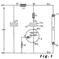
- the electronic power supply circuit illustrated in figure 1 comprises a first A1 and a second A2 power input pole to which an AC voltage, for example the 220 Volt of the mains, is applicable.
- a first coil L1 is connected between the first power input pole A1 and, via a first distribution line DL1, a first filament F1 of a fluorescent lamp FL.
- the presence of lamp FL in figure 1 is only shown for the sake of clarity, but it should be noted that the lamp is removably connected to the circuit and is thus not necessarily an integral part of the circuit.
- a second filament F2 of the fluorescent lamp FL is connected via a second distribution line DL2 to the second power input pole A2.
- a series connection of a second coil L2, a first capacitor C1 and a bi-directional AC switch S is connected in parallel with the lamp FL, in such a manner that a first coil pole of the second coil L2 is connected to the first distribution line DL1 whereas a second gate MT2 of the switch S is connected to the second distribution line DL2.
- the capacitor C1 is connected between a second coil pole of coil L2 and a first gate MT1 of the switch S.
- a trigger gate T of the switch is connected via a resistance R to the second power input pole A2.
- the bi-directional AC switch is preferably a triac including a diac trigger such as for example a Quadrac (registered trademark) manufactured by Teccor electronics.
- a second capacitor C2 is connected in parallel with the first A1 and second A2 power input pole.
- the purpose of this second capacitor C2 is to enable power saving such as will be described hereinafter.
- the first L1 and second L2 coil form a ballast for the lamp FL.
- the ballast together with the first capacitor and the switch S form a primary circuit.
- the secondary circuit is formed by the second capacitor C2.
- the two coils of the ballast have different uses.
- Coil L1 is mainly for the control of current passing through the fluorescent lamp FL, but primarily for helping in creating the high voltage across the first capacitor C1.
- the second coil L2, which is in series with the first coil L1, is far an additional inductances. In series with the capacitor C1, to ensure that the required open-circuit-voltage across the fluorescent lamp is attained.
- the ballast has three terminals, they are B1, B2 and B3.
- the first terminal, B1 is directly connected to the power input pole A1, and the first terminal of capacitor C2, the second terminal of the ballast B2, is directly connected to the first distribution line DL1, the third terminal, B3, of the ballast is directly connected to the first terminal of capacitor C1.
- the resistance R which is used in triggering the switch S will sense the current flowing into it and instantaneously trigger the bi-directional component which is incorporated inside the semiconductor switch, thereby switching on the latter and so charging the plate of capacitor connected via the first terminal, MT1, of switch positively.
- the switch S Since input pole A2 is negative, the switch S is no longer triggered causing the latter to become non-conductive.
- the first capacitor C1 will now discharge over the lamp FL. Since the switch is non-conductive, the only way for the first capacitor to discharge is via the second coil L2 of the ballast. Since the first capacitor C1 and the second coil L2 are chosen in such a manner as to form a resonant circuit, the capacitor C1 and coil L2 will resonantly discharge. Due to the branching of the first L1 and second coil L2 within the ballast, the resonant discharge current supplied during discharging of the first capacitor C1, will be added to the current supplied by the power source via the first coil L1. In such a manner a sufficient high voltage is created to start the fluorescent lamp FL.
- the electronic power supply circuit enables a quick start of the fluorescent lamp connected thereto. Once the semi-conductor switch S is triggered on the charging of current into the first capacitor it will react with the inductances in series and the result is the creation of a high voltage across the capacitor as well as subsequently across the load itself which is the fluorescent lamp.
- the circuit according to the invention can extend the life-span of a fluorescent lamp to its maximum specified burning hours. It doesn't need pre-heating of the filaments because the capacitor itself across the load creates the required high voltage to kick-off electrons inside to start the fluorescent lamp.
- ballast Since the ballast is not anymore used as the sole source of high voltage in starting the fluorescent lamp, variations of voltages with a minimum of 160 Volt cannot anymore hinder in starting the fluorescent lamp because the creation of high-voltage across the capacitor C1 is enough to start the fluorescent lamp.
- capacitor C2 is incorporated in the circuit for safety purposes and as well for power saving by reducing the current, without degrading the fluorescent lamps illumination.
- capacitor C1 During operation of the fluorescent lamp, once started, capacitor C1 will no longer be operational and only capacitor C2, is operating in parallel with the coil L1, of the ballast which is in series with the fluorescent lamp.
- LENZ LAW states that "in all cases of electromagnetic induction, the induced voltages have a direction such that the currents which they produce opposed the effect which produces them.”
- the coil L1 opposes the current going in through, thus it controls the current passing into the fluorescent lamp. From the peak voltage and decreasing to zero, the capacitor discharges to the coil trying to hold the voltage at the coil from decreasing.
- the coil Upon reaching zero voltage, the coil still have a stored magnetic field from the previous magnetic field direction. Hence the direction of electric current is still the same as with the first cycle.
- next half cycle is increasing from zero to peak voltage in the other direction. Since the previous current is opposite in direction and coming from the stored magnetic field, the current in the next half cycle is opposed so that the current going into the system is drastically reduced into half if the resonant frequency is equal to the line frequency which is 60 Hertz.
- the inductive reactance is primarily controlling the current into the fluorescent lamp by LENZ LAW. But the addition of current coming from the capacitor into the coil by its leading current explains that the capacitive reactance is virtually in series with the inductive reactance of the coil.
Landscapes
- Circuit Arrangements For Discharge Lamps (AREA)
Applications Claiming Priority (2)
| Application Number | Priority Date | Filing Date | Title |
|---|---|---|---|
| PH11999000897 | 1999-04-21 | ||
| PH9900897 | 1999-04-21 |
Publications (2)
| Publication Number | Publication Date |
|---|---|
| EP1047285A2 true EP1047285A2 (de) | 2000-10-25 |
| EP1047285A3 EP1047285A3 (de) | 2003-01-02 |
Family
ID=19929888
Family Applications (1)
| Application Number | Title | Priority Date | Filing Date |
|---|---|---|---|
| EP00870081A Withdrawn EP1047285A3 (de) | 1999-04-21 | 2000-04-21 | Vorschaltgerät für eine Leuchtstofflampe, mit elektronischer Startschaltung und Resonanzkondensator zum Senken des Eingangstroms |
Country Status (5)
| Country | Link |
|---|---|
| EP (1) | EP1047285A3 (de) |
| CN (1) | CN2420813Y (de) |
| CA (1) | CA2300351A1 (de) |
| SG (1) | SG85170A1 (de) |
| TW (1) | TW469755B (de) |
Cited By (1)
| Publication number | Priority date | Publication date | Assignee | Title |
|---|---|---|---|---|
| ITRM20100028A1 (it) * | 2010-01-27 | 2011-07-28 | Gmm Tecnologia S R L | "innovativo starter per lampade a fluorescenza" |
Family Cites Families (9)
| Publication number | Priority date | Publication date | Assignee | Title |
|---|---|---|---|---|
| BE857930A (fr) * | 1977-08-19 | 1978-02-20 | Acec | Dispositif de commande pour lampes a decharges |
| US4376911A (en) * | 1979-12-28 | 1983-03-15 | New Nippon Electric Co., Ltd. | Circuit system for lighting a discharge lamp or lamps |
| FR2493598A1 (fr) * | 1980-10-30 | 1982-05-07 | Claude Sa | Amorceur pour lampe a decharge |
| DE3047289A1 (de) * | 1980-12-16 | 1982-07-29 | Patent-Treuhand-Gesellschaft für elektrische Glühlampen mbH, 8000 München | Zuendvorrichtung fuer eine niederdruckentladungslampe |
| DE3311215A1 (de) * | 1983-03-28 | 1984-10-04 | Patent-Treuhand-Gesellschaft für elektrische Glühlampen mbH, 8000 München | Zuendvorrichtung fuer eine niederdruckentladungslampe |
| US4885507A (en) * | 1987-07-21 | 1989-12-05 | Ham Byung I | Electronic starter combined with the L-C ballast of a fluorescent lamp |
| GB2225498A (en) * | 1988-11-22 | 1990-05-30 | King Chuen Hector Chu | Fluorescent lamp ignition circuit |
| US5023521A (en) * | 1989-12-18 | 1991-06-11 | Radionic Industries, Inc. | Lamp ballast system |
| US6037722A (en) * | 1994-09-30 | 2000-03-14 | Pacific Scientific | Dimmable ballast apparatus and method for controlling power delivered to a fluorescent lamp |
-
2000
- 2000-03-10 CA CA 2300351 patent/CA2300351A1/en not_active Abandoned
- 2000-04-15 SG SG200002175A patent/SG85170A1/en unknown
- 2000-04-20 CN CN 00209605 patent/CN2420813Y/zh not_active Expired - Fee Related
- 2000-04-21 EP EP00870081A patent/EP1047285A3/de not_active Withdrawn
- 2000-07-14 TW TW89114021A patent/TW469755B/zh not_active IP Right Cessation
Cited By (1)
| Publication number | Priority date | Publication date | Assignee | Title |
|---|---|---|---|---|
| ITRM20100028A1 (it) * | 2010-01-27 | 2011-07-28 | Gmm Tecnologia S R L | "innovativo starter per lampade a fluorescenza" |
Also Published As
| Publication number | Publication date |
|---|---|
| TW469755B (en) | 2001-12-21 |
| CA2300351A1 (en) | 2000-10-21 |
| CN2420813Y (zh) | 2001-02-21 |
| SG85170A1 (en) | 2001-12-19 |
| EP1047285A3 (de) | 2003-01-02 |
Similar Documents
| Publication | Publication Date | Title |
|---|---|---|
| EP0093469B1 (de) | Gleichstrom/Wechselstromumformer für Zündung und Speisung von Gas- oder Dampfentladungslampen | |
| US4538093A (en) | Variable frequency start circuit for discharge lamp with preheatable electrodes | |
| EP1987705B1 (de) | Spannungsgespeister wandler für leuchtstofflampen | |
| JPH0318000A (ja) | 放電灯調光装置 | |
| EP1127478A2 (de) | Leistungssteuerungsschaltung für ein vorschaltgerät | |
| US6815908B2 (en) | Dimmable self-oscillating electronic ballast for fluorescent lamp | |
| US5387849A (en) | Lamp ballast system characterized by a power factor correction of greater than or equal to 90% | |
| EP0132008B1 (de) | Mit einem Wechselrichter ausgerüstete Energieversorgungseinrichtung zum Entzünden und Speisen von Gas- und/oder Dampfentladungslampen | |
| CN101796889B (zh) | 线性荧光灯镇流器的热返送 | |
| WO2009108441A1 (en) | Dimmable instant start ballast | |
| JPH06188091A (ja) | 放電灯点弧及び点灯回路配置 | |
| US6194843B1 (en) | HID ballast with hot restart circuit | |
| US3836817A (en) | Two-pole electronic starter for fluorescent lamps | |
| JPH01134899A (ja) | ガス放電灯点孤及び給電用dc/acコンバータ | |
| US4520295A (en) | Step-wise dimmer control circuit for a discharge lamp | |
| US6674249B1 (en) | Resistively ballasted gaseous discharge lamp circuit and method | |
| EP1047285A2 (de) | Vorschaltgerät für eine Leuchtstofflampe, mit elektronischer Startschaltung und Resonanzkondensator zum Senken des Eingangstroms | |
| KR100396386B1 (ko) | 가스방전램프의트리거회로 | |
| EP0313134A1 (de) | Elektrische Anordnung zum Zünden und Speisen einer Gasentladungslampe | |
| JP5497450B2 (ja) | 誘導駆動ガス放電ランプ回路 | |
| US5013970A (en) | Peak voltage reducer circuit for fluorescent lamps | |
| KR20060051258A (ko) | 예열가능 전극들을 갖는 방전 램프를 위한 펌프 회로를갖는 전자 안정기 | |
| JPH0963779A (ja) | 瞬間点灯式蛍光灯点灯回路 | |
| KR100314467B1 (ko) | 순간 점등식 형광등 안정기 | |
| JPS59130091A (ja) | 放電灯点灯装置 |
Legal Events
| Date | Code | Title | Description |
|---|---|---|---|
| PUAI | Public reference made under article 153(3) epc to a published international application that has entered the european phase |
Free format text: ORIGINAL CODE: 0009012 |
|
| AK | Designated contracting states |
Kind code of ref document: A2 Designated state(s): AT BE CH CY DE DK ES FI FR GB GR IE IT LI LU MC NL PT SE |
|
| AX | Request for extension of the european patent |
Free format text: AL;LT;LV;MK;RO;SI |
|
| PUAL | Search report despatched |
Free format text: ORIGINAL CODE: 0009013 |
|
| AK | Designated contracting states |
Kind code of ref document: A3 Designated state(s): AT BE CH CY DE DK ES FI FR GB GR IE IT LI LU MC NL PT SE |
|
| AX | Request for extension of the european patent |
Free format text: AL;LT;LV;MK;RO;SI |
|
| AKX | Designation fees paid | ||
| REG | Reference to a national code |
Ref country code: DE Ref legal event code: 8566 |
|
| STAA | Information on the status of an ep patent application or granted ep patent |
Free format text: STATUS: THE APPLICATION IS DEEMED TO BE WITHDRAWN |
|
| 18D | Application deemed to be withdrawn |
Effective date: 20030703 |