EP1046566A2 - Steering wheel and method for manufacturing same - Google Patents
Steering wheel and method for manufacturing same Download PDFInfo
- Publication number
- EP1046566A2 EP1046566A2 EP20000301594 EP00301594A EP1046566A2 EP 1046566 A2 EP1046566 A2 EP 1046566A2 EP 20000301594 EP20000301594 EP 20000301594 EP 00301594 A EP00301594 A EP 00301594A EP 1046566 A2 EP1046566 A2 EP 1046566A2
- Authority
- EP
- European Patent Office
- Prior art keywords
- rim
- steering wheel
- core
- elements
- section
- Prior art date
- Legal status (The legal status is an assumption and is not a legal conclusion. Google has not performed a legal analysis and makes no representation as to the accuracy of the status listed.)
- Withdrawn
Links
- 238000000034 method Methods 0.000 title claims description 39
- 238000004519 manufacturing process Methods 0.000 title claims description 19
- 239000002023 wood Substances 0.000 claims abstract description 47
- 239000000463 material Substances 0.000 claims abstract description 31
- 229920003002 synthetic resin Polymers 0.000 claims abstract description 25
- 239000000057 synthetic resin Substances 0.000 claims abstract description 25
- 239000007788 liquid Substances 0.000 claims description 30
- 238000010023 transfer printing Methods 0.000 claims description 29
- 238000005452 bending Methods 0.000 claims description 22
- 230000002093 peripheral effect Effects 0.000 claims description 22
- 239000008188 pellet Substances 0.000 claims description 13
- 239000011248 coating agent Substances 0.000 claims description 12
- 238000000576 coating method Methods 0.000 claims description 12
- 230000001105 regulatory effect Effects 0.000 claims description 12
- 238000010438 heat treatment Methods 0.000 claims description 8
- 239000000049 pigment Substances 0.000 claims description 7
- 230000015572 biosynthetic process Effects 0.000 claims description 6
- 238000005304 joining Methods 0.000 claims description 6
- 238000001816 cooling Methods 0.000 claims description 4
- 230000000694 effects Effects 0.000 claims description 3
- 230000001747 exhibiting effect Effects 0.000 claims description 3
- 239000002994 raw material Substances 0.000 description 10
- 238000000465 moulding Methods 0.000 description 9
- UQSXHKLRYXJYBZ-UHFFFAOYSA-N Iron oxide Chemical compound [Fe]=O UQSXHKLRYXJYBZ-UHFFFAOYSA-N 0.000 description 6
- 229920005989 resin Polymers 0.000 description 6
- 239000011347 resin Substances 0.000 description 6
- 238000007493 shaping process Methods 0.000 description 6
- GWEVSGVZZGPLCZ-UHFFFAOYSA-N Titan oxide Chemical compound O=[Ti]=O GWEVSGVZZGPLCZ-UHFFFAOYSA-N 0.000 description 5
- 239000000853 adhesive Substances 0.000 description 5
- 230000001070 adhesive effect Effects 0.000 description 5
- 238000001746 injection moulding Methods 0.000 description 5
- 239000001023 inorganic pigment Substances 0.000 description 5
- OGIDPMRJRNCKJF-UHFFFAOYSA-N titanium oxide Inorganic materials [Ti]=O OGIDPMRJRNCKJF-UHFFFAOYSA-N 0.000 description 5
- 229920001895 acrylonitrile-acrylic-styrene Polymers 0.000 description 4
- 238000010276 construction Methods 0.000 description 4
- 238000001125 extrusion Methods 0.000 description 4
- 238000002360 preparation method Methods 0.000 description 4
- 238000000227 grinding Methods 0.000 description 3
- 230000008569 process Effects 0.000 description 3
- XECAHXYUAAWDEL-UHFFFAOYSA-N acrylonitrile butadiene styrene Chemical compound C=CC=C.C=CC#N.C=CC1=CC=CC=C1 XECAHXYUAAWDEL-UHFFFAOYSA-N 0.000 description 2
- 239000004676 acrylonitrile butadiene styrene Substances 0.000 description 2
- 229920000122 acrylonitrile butadiene styrene Polymers 0.000 description 2
- CJOBVZJTOIVNNF-UHFFFAOYSA-N cadmium sulfide Chemical compound [Cd]=S CJOBVZJTOIVNNF-UHFFFAOYSA-N 0.000 description 2
- 239000006229 carbon black Substances 0.000 description 2
- 238000013329 compounding Methods 0.000 description 2
- 229910052751 metal Inorganic materials 0.000 description 2
- 239000002184 metal Substances 0.000 description 2
- 238000003825 pressing Methods 0.000 description 2
- 238000003892 spreading Methods 0.000 description 2
- 230000007480 spreading Effects 0.000 description 2
- 241000723346 Cinnamomum camphora Species 0.000 description 1
- 229920002943 EPDM rubber Polymers 0.000 description 1
- JOYRKODLDBILNP-UHFFFAOYSA-N Ethyl urethane Chemical compound CCOC(N)=O JOYRKODLDBILNP-UHFFFAOYSA-N 0.000 description 1
- 240000000249 Morus alba Species 0.000 description 1
- 235000008708 Morus alba Nutrition 0.000 description 1
- 241000190021 Zelkova Species 0.000 description 1
- 244000126002 Ziziphus vulgaris Species 0.000 description 1
- 235000008529 Ziziphus vulgaris Nutrition 0.000 description 1
- 239000012190 activator Substances 0.000 description 1
- 238000005336 cracking Methods 0.000 description 1
- 238000005520 cutting process Methods 0.000 description 1
- 238000005034 decoration Methods 0.000 description 1
- 238000005187 foaming Methods 0.000 description 1
- 230000004927 fusion Effects 0.000 description 1
- 238000004898 kneading Methods 0.000 description 1
- 239000000203 mixture Substances 0.000 description 1
- 238000012986 modification Methods 0.000 description 1
- 230000004048 modification Effects 0.000 description 1
- 239000005445 natural material Substances 0.000 description 1
- 239000002245 particle Substances 0.000 description 1
- 239000000843 powder Substances 0.000 description 1
- 238000007639 printing Methods 0.000 description 1
- 230000002787 reinforcement Effects 0.000 description 1
- 238000009877 rendering Methods 0.000 description 1
- 238000010008 shearing Methods 0.000 description 1
- 239000002904 solvent Substances 0.000 description 1
- 239000007858 starting material Substances 0.000 description 1
- 229920001169 thermoplastic Polymers 0.000 description 1
- 239000004416 thermosoftening plastic Substances 0.000 description 1
- 230000009466 transformation Effects 0.000 description 1
- 238000003466 welding Methods 0.000 description 1
Images



Classifications
-
- B—PERFORMING OPERATIONS; TRANSPORTING
- B29—WORKING OF PLASTICS; WORKING OF SUBSTANCES IN A PLASTIC STATE IN GENERAL
- B29C—SHAPING OR JOINING OF PLASTICS; SHAPING OF MATERIAL IN A PLASTIC STATE, NOT OTHERWISE PROVIDED FOR; AFTER-TREATMENT OF THE SHAPED PRODUCTS, e.g. REPAIRING
- B29C69/00—Combinations of shaping techniques not provided for in a single one of main groups B29C39/00 - B29C67/00, e.g. associations of moulding and joining techniques; Apparatus therefore
-
- B—PERFORMING OPERATIONS; TRANSPORTING
- B62—LAND VEHICLES FOR TRAVELLING OTHERWISE THAN ON RAILS
- B62D—MOTOR VEHICLES; TRAILERS
- B62D1/00—Steering controls, i.e. means for initiating a change of direction of the vehicle
- B62D1/02—Steering controls, i.e. means for initiating a change of direction of the vehicle vehicle-mounted
- B62D1/04—Hand wheels
- B62D1/06—Rims, e.g. with heating means; Rim covers
-
- B—PERFORMING OPERATIONS; TRANSPORTING
- B29—WORKING OF PLASTICS; WORKING OF SUBSTANCES IN A PLASTIC STATE IN GENERAL
- B29C—SHAPING OR JOINING OF PLASTICS; SHAPING OF MATERIAL IN A PLASTIC STATE, NOT OTHERWISE PROVIDED FOR; AFTER-TREATMENT OF THE SHAPED PRODUCTS, e.g. REPAIRING
- B29C41/00—Shaping by coating a mould, core or other substrate, i.e. by depositing material and stripping-off the shaped article; Apparatus therefor
-
- B—PERFORMING OPERATIONS; TRANSPORTING
- B29—WORKING OF PLASTICS; WORKING OF SUBSTANCES IN A PLASTIC STATE IN GENERAL
- B29C—SHAPING OR JOINING OF PLASTICS; SHAPING OF MATERIAL IN A PLASTIC STATE, NOT OTHERWISE PROVIDED FOR; AFTER-TREATMENT OF THE SHAPED PRODUCTS, e.g. REPAIRING
- B29C48/00—Extrusion moulding, i.e. expressing the moulding material through a die or nozzle which imparts the desired form; Apparatus therefor
-
- B—PERFORMING OPERATIONS; TRANSPORTING
- B29—WORKING OF PLASTICS; WORKING OF SUBSTANCES IN A PLASTIC STATE IN GENERAL
- B29C—SHAPING OR JOINING OF PLASTICS; SHAPING OF MATERIAL IN A PLASTIC STATE, NOT OTHERWISE PROVIDED FOR; AFTER-TREATMENT OF THE SHAPED PRODUCTS, e.g. REPAIRING
- B29C48/00—Extrusion moulding, i.e. expressing the moulding material through a die or nozzle which imparts the desired form; Apparatus therefor
- B29C48/001—Combinations of extrusion moulding with other shaping operations
-
- B—PERFORMING OPERATIONS; TRANSPORTING
- B29—WORKING OF PLASTICS; WORKING OF SUBSTANCES IN A PLASTIC STATE IN GENERAL
- B29C—SHAPING OR JOINING OF PLASTICS; SHAPING OF MATERIAL IN A PLASTIC STATE, NOT OTHERWISE PROVIDED FOR; AFTER-TREATMENT OF THE SHAPED PRODUCTS, e.g. REPAIRING
- B29C48/00—Extrusion moulding, i.e. expressing the moulding material through a die or nozzle which imparts the desired form; Apparatus therefor
- B29C48/001—Combinations of extrusion moulding with other shaping operations
- B29C48/0022—Combinations of extrusion moulding with other shaping operations combined with cutting
-
- B—PERFORMING OPERATIONS; TRANSPORTING
- B29—WORKING OF PLASTICS; WORKING OF SUBSTANCES IN A PLASTIC STATE IN GENERAL
- B29C—SHAPING OR JOINING OF PLASTICS; SHAPING OF MATERIAL IN A PLASTIC STATE, NOT OTHERWISE PROVIDED FOR; AFTER-TREATMENT OF THE SHAPED PRODUCTS, e.g. REPAIRING
- B29C48/00—Extrusion moulding, i.e. expressing the moulding material through a die or nozzle which imparts the desired form; Apparatus therefor
- B29C48/03—Extrusion moulding, i.e. expressing the moulding material through a die or nozzle which imparts the desired form; Apparatus therefor characterised by the shape of the extruded material at extrusion
- B29C48/06—Rod-shaped
-
- B—PERFORMING OPERATIONS; TRANSPORTING
- B29—WORKING OF PLASTICS; WORKING OF SUBSTANCES IN A PLASTIC STATE IN GENERAL
- B29C—SHAPING OR JOINING OF PLASTICS; SHAPING OF MATERIAL IN A PLASTIC STATE, NOT OTHERWISE PROVIDED FOR; AFTER-TREATMENT OF THE SHAPED PRODUCTS, e.g. REPAIRING
- B29C48/00—Extrusion moulding, i.e. expressing the moulding material through a die or nozzle which imparts the desired form; Apparatus therefor
- B29C48/03—Extrusion moulding, i.e. expressing the moulding material through a die or nozzle which imparts the desired form; Apparatus therefor characterised by the shape of the extruded material at extrusion
- B29C48/12—Articles with an irregular circumference when viewed in cross-section, e.g. window profiles
-
- B—PERFORMING OPERATIONS; TRANSPORTING
- B29—WORKING OF PLASTICS; WORKING OF SUBSTANCES IN A PLASTIC STATE IN GENERAL
- B29C—SHAPING OR JOINING OF PLASTICS; SHAPING OF MATERIAL IN A PLASTIC STATE, NOT OTHERWISE PROVIDED FOR; AFTER-TREATMENT OF THE SHAPED PRODUCTS, e.g. REPAIRING
- B29C53/00—Shaping by bending, folding, twisting, straightening or flattening; Apparatus therefor
- B29C53/02—Bending or folding
- B29C53/08—Bending or folding of tubes or other profiled members
-
- B—PERFORMING OPERATIONS; TRANSPORTING
- B29—WORKING OF PLASTICS; WORKING OF SUBSTANCES IN A PLASTIC STATE IN GENERAL
- B29C—SHAPING OR JOINING OF PLASTICS; SHAPING OF MATERIAL IN A PLASTIC STATE, NOT OTHERWISE PROVIDED FOR; AFTER-TREATMENT OF THE SHAPED PRODUCTS, e.g. REPAIRING
- B29C63/00—Lining or sheathing, i.e. applying preformed layers or sheathings of plastics; Apparatus therefor
- B29C63/22—Lining or sheathing, i.e. applying preformed layers or sheathings of plastics; Apparatus therefor using layers or sheathings having a shape adapted to the shape of the article
-
- B—PERFORMING OPERATIONS; TRANSPORTING
- B29—WORKING OF PLASTICS; WORKING OF SUBSTANCES IN A PLASTIC STATE IN GENERAL
- B29K—INDEXING SCHEME ASSOCIATED WITH SUBCLASSES B29B, B29C OR B29D, RELATING TO MOULDING MATERIALS OR TO MATERIALS FOR MOULDS, REINFORCEMENTS, FILLERS OR PREFORMED PARTS, e.g. INSERTS
- B29K2711/00—Use of natural products or their composites, not provided for in groups B29K2601/00 - B29K2709/00, for preformed parts, e.g. for inserts
- B29K2711/14—Wood, e.g. woodboard or fibreboard
-
- B—PERFORMING OPERATIONS; TRANSPORTING
- B29—WORKING OF PLASTICS; WORKING OF SUBSTANCES IN A PLASTIC STATE IN GENERAL
- B29L—INDEXING SCHEME ASSOCIATED WITH SUBCLASS B29C, RELATING TO PARTICULAR ARTICLES
- B29L2031/00—Other particular articles
- B29L2031/001—Profiled members, e.g. beams, sections
- B29L2031/003—Profiled members, e.g. beams, sections having a profiled transverse cross-section
-
- B—PERFORMING OPERATIONS; TRANSPORTING
- B29—WORKING OF PLASTICS; WORKING OF SUBSTANCES IN A PLASTIC STATE IN GENERAL
- B29L—INDEXING SCHEME ASSOCIATED WITH SUBCLASS B29C, RELATING TO PARTICULAR ARTICLES
- B29L2031/00—Other particular articles
- B29L2031/30—Vehicles, e.g. ships or aircraft, or body parts thereof
- B29L2031/3047—Steering wheels
-
- Y—GENERAL TAGGING OF NEW TECHNOLOGICAL DEVELOPMENTS; GENERAL TAGGING OF CROSS-SECTIONAL TECHNOLOGIES SPANNING OVER SEVERAL SECTIONS OF THE IPC; TECHNICAL SUBJECTS COVERED BY FORMER USPC CROSS-REFERENCE ART COLLECTIONS [XRACs] AND DIGESTS
- Y10—TECHNICAL SUBJECTS COVERED BY FORMER USPC
- Y10T—TECHNICAL SUBJECTS COVERED BY FORMER US CLASSIFICATION
- Y10T74/00—Machine element or mechanism
- Y10T74/20—Control lever and linkage systems
- Y10T74/20576—Elements
- Y10T74/20732—Handles
- Y10T74/20834—Hand wheels
Definitions
- This invention relates to a steering wheel for a vehicle, and more particularly to a steering wheel having both an appearance and feel of wood like that of natural wood and a method for manufacturing the same.
- a steering wheel for a vehicle is kept grasped by a driver during driving of the vehicle, thus, it is essential that the steering wheel not only exhibits a satisfactory appearance but is pleasant to the touch.
- Such pleasant touch means that the steering wheel does not exhibit an excessively smooth feel, a rough feel or a tacky feel. Also, it means that the steering wheel is not slippery, excessively hot or excessively cold.
- Such requirements for the pleasant touch are sufficiently satisfied by a conventional wooden steering wheel.
- the wooden steering wheel causes distortion peculiar to a natural tree material due to a variation in ambient temperature, irradiation of direct sun beams thereon, a variation in ambient moisture and the like. This results in peeling of the wooden steering wheel, cracking thereof and the like.
- the wooden steering wheel is not suitable for mass production because currently there is a shortage of natural wood material available.
- a steering wheel which is constructed so as to have the feel of wood like that of natural wood has been recently substituted for the wooden steering wheel in the market.
- Such a substitute steering wheel is generally manufactured by forming a suitable synthetic resin material into a rim section for the steering wheel by molding and applying the appearance of wood to the rim section.
- Such application of the appearance of wood is carried out using either techniques of providing an appearance of the thus-formed rim section with the feel of wood or techniques of subjecting a synthetic resin material which has woodmeal previously added thereto to injection molding to form a rim section.
- the latter techniques provide the steering wheel with not only the feel of wood but an appearance of wood due to a stream or flow pattern formed on the rim section during the injection molding.
- the former techniques are disadvantageous in that printing on the rim section carried out after the above-described molding fails to provide the steering wheel with a satisfactory feel of wood, although it provides the steering wheel with an appearance which is very similar to that of natural wood.
- the latter techniques of injection molding the synthetic resin material having the woodmeal added thereto fail to permit the steering wheel to exhibit a satisfactory appearance of wood although they provide it with an improved feel of wood. More particularly, in the latter techniques, the flow pattern formed during the injection molding is excessively emphasized due to foaming of moisture held in the woodmeal. Also, the latter techniques cause discolouration of the woodmeal due to generation of heat from the woodmeal by high shearing.
- the flow pattern formed during the injection molding is principally based on a curved flow pattern formed by a phenomenon that synthetic resin materials injected from several gates freely flow in a mold cavity and then merge with each other.
- the curved flow pattern is formed by spreading of the synthetic resin materials from the gates and swirling of the materials in places. If such spreading and swirling of the synthetic resin materials permitted the curved flow pattern to be finely formed, the steering wheel would be provided with an appearance of high quality in imitation of precious wood which provides a pretty grain pattern of wood, such as a circular grain pattern, a grape-like grain pattern, or the like as seen in a zelkova tree, a mulberry tree, a camphor tree, a jujube tree or the like.
- the techniques currently practiced fail to provide the steering wheel with the feeling of high-grade wood in appearance.
- an appearance of wood which is substantially equal to or the same as that of natural wood does not refer to an appearance of precious wood having a pretty grain pattern of wood, such as a circular grain pattern, a grape-like grain pattern, or the like. Rather, it refers to a general woodgrain such as a straight grain or a cross grain.
- a woodgrain is formed on a rim section of the steering wheel while defining a flow pattern in a circumferential direction of the rim section, to thereby give the impression that the flow pattern is formed by a sliced veneer.
- a steering wheel in accordance with one aspect of the present invention, includes a rim section having a core incorporated therein.
- the rim section is constituted by rim elements made of a thermosoftening synthetic resin material to which woodmeal is added, resulting in the rim section being formed thereon with a flow pattern.
- the rim elements are each re-shaped from a straight rod-like configuration into an arcuate configuration in conformity to a curvature of the core and mounted on the core, so that the flow pattern may be transformed into an annular flow pattern.
- Such construction of the present invention permits the steering wheel to give the impression that the steering wheel is formed thereon with a woodgrain pattern in a manner to extend in a circumferential direction thereof, so that it may have both an appearance and feel of wood which is substantially equal to that of natural wood.
- thermosoftening synthetic resin material has a colour pigment added thereto so that the flow pattern is formed in an annular flow pattern which has a clear woodgrain emphasized by the colour pigment added.
- the steering wheel of such a preferred embodiment of the present invention gives the strong impression that it is formed thereon with a woodgrain pattern as if it is formed by a sliced veneer.
- the rim section is formed thereon with an uneven portion to facilitate holding, in such a manner that the flow pattern is transformed into the annular flow pattern while preventing the thus-formed annular flow pattern from being disordered by the unevenness.
- the steering wheel of such an embodiment of the present invention gives the strong impression that it is formed thereon with a woodgrain pattern as if the unevenness on the steering wheel is formed by cutting of natural wood.
- a method for manufacturing a steering wheel includes the steps of extruding a thermosoftening synthetic resin to which woodmeal is added to prepare a pair of straight rod-like rim elements, bending the straight rod-like rim elements into an arcuate shape in conformity to a curvature of a core while keeping the rim elements softened, and mounting the rim elements thus bent on the core while interposing the core therebetween.
- the method permits mass-production of a steering wheel which gives the impression that it is formed thereon with a woodgrain pattern in a manner to extend in a circumferential direction thereof, resulting in the steering wheel having both an appearance and feel of wood which is substantially equal to that of natural wood.
- the extruding step is carried out using a nozzle formed to have a semicircular shape in section having an arc section formed substantially in conformity to an arcuate shape which is a half of a sectional configuration of a rim section of a finished steering wheel and which is defined at an outermost portion of the rim section and a chord section projectingly provided with a core corresponding section which is formed substantially in conformity to a half of a sectional configuration of the core, resulting in the rim elements being prepared in the form of a straight rod-like shape.
- Such construction permits mounting of the rim elements on the core to be carried out in the subsequent step, to thereby prevent disorder of the flow pattern in the circumferential or annular direction during re-shaping of the rim elements.
- the bending step is carried out using a regulating die formed thereon with projections for forming an uneven portion for holding and a forcing die, wherein the straight rod-like rim elements are each softened by re-heating to be roughly bent into an arcuate shape and then fitted in the regulating die, then pressed by means of the forcing die, during which the regulating die and forcing die cooperate with each other to define an arcuate cavity having a vacant region defined at each of opposite ends thereof in a longitudinal direction thereof.
- the method of the present invention attains satisfactory re-shaping of the rim elements while effectively preventing disorder of the flow pattern in the circumferential direction.
- the mounting step is carried out by mounting the front and rear side rim elements on the core while adhesively joining the front and rear rim elements to each other.
- Such construction permits joints between the front side rim element and the rear side rim element to be positioned at an outermost periphery of the rim section and an innermost periphery thereof, so that the joints may be substantially out of sight of a driver. Also, it permits mounting of the rim elements on the core to be attained with increased strength.
- the pair of rim elements each include an inner peripheral side rim element and an outer peripheral side rim element opposite to the front side rim element.
- the mounting step is carried out by mounting the inner and outer peripheral side rim elements on the core while adhesively joining the inner and outer peripheral side rim elements to each other. This causes joints between both rim elements to appear on a front side of the rim section which is observable from a driver's seat and a rear side thereof which is not observable from the driver's seat.
- it is merely required to cover the front side joint with a molding or the like.
- the mounting step includes mounting a cover member, such as a molding, an ebony-patterned member, or the like on a joint between the rim elements. This not only effectively hides the joint but provides the steering wheel with a decorative effect. Also, it permits joining between the rim elements to be strengthened.
- a cover member such as a molding, an ebony-patterned member, or the like
- thermosoftening synthetic resin material which is fed in the extruding step is constituted by a combination of pellets having the woodmeal kneadingly incorporated therein and pellets having a colour pigment added thereto as well as the woodmeal and exhibiting a colour different from that of the former pellets.
- the method further includes the step of applying a coating to the rim elements, wherein the coating is applied to a front side of the rim elements observable from a driver's seat. This minimizes a stain on the front side of the rim section while preventing the feel of wood on the rear side thereof from being deteriorated.
- the method further includes the step of carrying out liquid pressure transfer printing of the rim elements, wherein the transfer print is applied to a front side of the rim elements observable from a driver's seat. Also, the liquid pressure transfer printing is carried out so as to permit formation of a transfer printing pattern by gradations on the rim elements wherein a transfer ink layer is gradually reduced in thickness toward a rear side of the rim elements, whereby a ground pattern gradually appears on the rim elements.
- a starting material of which a rim section for the steering wheel is made will be referred to as a raw material A0
- a straight rod-like member formed of the raw material A0 by extrusion will be referred to as a straight rim element A1
- an arcuate member formed by bending the rim element A1 will be referred to as an arcuate rim element A2.
- a steering wheel of the illustrated embodiment which is generally designated by reference numeral 1 generally includes a boss section 2 acting as a centre of rotational movement of the steering wheel 1, spoke sections 3 arranged so as to radially extend from the boss section 2, and a rim section 4 connected to a distal end of each of the spoke sections 3 and formed to have an annular shape.
- the rim section 4 is constituted by a long rim portion 41 of an elongated arcuate shape (positioned on an upper side in Fig. 1A), a short rim portion 42 of a short arcuate shape (positioned on a lower side in Fig.
- the rim section 4 has a core 44 incorporated therein, which may be formed by bending a metal rod into an annular shape by way of example.
- the long rim portion 41, short rim portion 42 and grip portions 43 are mounted on the core 44, to thereby provide the rim section 4.
- the spoke sections 3 may be made of metal and welded directly to the core 44, so that the grip portions 43 may be formed of flexible urethane by insert molding so as to extend over both core 44 and spoke sections 3.
- the long rim portion 41 and short rim portion 42 are mounted on the core 44 on which the grip portions 43 are thus molded, resulting in a so-called combination steering wheel being provided.
- the grip portions 43 may each be mounted therein with a rim element A2 of an arcuate shape.
- the long rim portion 41 and short rim portion 42 are each constituted by two halves formed so as to extend in a longitudinal direction thereof, resulting in interposedly holding the core 44 therebetween.
- the two halves are adhesively joined to each other to provide each of the long rim portion 41 and short rim portion 42. More specifically, supposing that the long rim portion 41 and short rim portion 42 are mounted in a vehicle, a front side member of the long rim portion 41 which is observable from a driver's seat is designated by reference character 41a and that of the short rim portion 42 observable therefrom is 42a.
- rear side members of the long rim portion 41 and short rim portion 42 which are not observable from the driver's seat or are out of sight of the driver are designated by reference characters 41b and 42b, respectively.
- the front and rear side members 41a and 41b of the long rim portion 41 are each formed to have a substantially semicircular shape in section by way of example. This is true of the front and rear side members 42a and 42b of the short rim portion 42.
- the front and rear side members of the long and short rim portions 41 and 42 are each formed at a central portion thereof with a core holding recess 45 in a manner to extend in a longitudinal direction thereof.
- the long rim portion 41 and short rim portion 42 are each constituted by the two front and rear side members joined to each other.
- the long and short rim portions 41 and 42 may be configured as shown in Fig. 5B. More specifically, in Fig. 5B, the front side members 41a and 42a of the long and short rim portions 41 and 42 are each formed to have a substantially C-shape in section, so that the core 44 is received therein from a side of a rear surface thereof. Also, the rear side member 41b of the long rim portion 41 and the rear side member 42b of the short rim portion 42 are each formed to have a thickness substantially equal to a thickness of the core 44, to thereby close the core holding recess 45.
- the rim section 4 is constituted of such front and rear side members as described above. It may be configured as shown in Figs. 7A and 7B. More particularly, the long rim portion 41 is constituted of two halves or an inner peripheral side member 41c and an outer peripheral side member 41d and the short rim portion 42 is constituted of two halves or an inner peripheral side member 42c and an outer peripheral side member 42d. Such configuration of Figs. 7A and 7B causes joints between the inner peripheral side member 41c (42c) and the outer peripheral side member 41d (42d) to appear on both a front position observable from the driver's seat and a rear position out of sight of the driver.
- a cover member 46 such a molding, an element formed thereon with an ebony-like pattern or the like may be attached to at least the front joint to hide it from view.
- Such attachment of the cover member 46 to the joints may be likewise applied to the rim section 4 constituted of the front side member and rear side member as described above.
- Attachment of the cover member 46 to the joints of the rim section 4 may be carried out by forming each of the inner and outer peripheral side members or front and rear side members with a recess and interposedly fitting both ends of the cover member 46 formed to have a substantially C-shape into the respective recesses of the side members. This also ensures reinforcement of the rim section 4.
- reference numerals 41e, 41f, 42e and 42f designate non-slip holding unevenness formed on the rear side of the rim section 4.
- the raw material A0 essentially consists of a thermoplastic or thermosoftening synthetic resin material such as AAS (acrylonitrile acrylic styrene) resin, AES (acrylonitrile- (ethylene-propylene-diene terpolymer)-styrene) resin, ABS (acrylonitrile butadiene styrene) resin or the like.
- AAS acrylonitrile acrylic styrene
- AES acrylonitrile- (ethylene-propylene-diene terpolymer)-styrene
- ABS acrylonitrile butadiene styrene
- the raw material may be constituted by AAS (acrylonitrile acrylic styrene) resin acting as a main component and woodmeal of 60 ⁇ m in average particle diameter in an amount of 20% which has an inorganic pigment such as titanium oxide or the like incorporated therein.
- AAS acrylonitrile acrylic styrene
- the woodmeal referred to herein includes not a mere wood powder (wood shavings) but a mixture of the woodmeal with an inorganic pigment such as titanium oxide, iron oxide, cadmium yellow, carbon black or the like added thereto so as to permit the woodmeal to withstand an elevated temperature during the molding.
- an inorganic pigment such as titanium oxide, iron oxide, cadmium yellow, carbon black or the like
- a product commercially available under "TECHNOMATERIAL” (trademark) from MISAWA HOMES CO., LTD. may be suitably used.
- the raw material exhibits a colour within a range between light brown and a flesh colour, because titanium oxide has a white colour.
- woodmeal having iron oxide or an inorganic pigment such as cadmium yellow, carbon black or the like incorporated thereinto permits the raw material to exhibit a different appearance colour, such as dark brown or the like, because the iron oxide or the inorganic pigment has a colour other than a white colour.
- the amount of each of the synthetic resin material and woodmeal added thereto may be suitably varied depending on various conditions such as molding conditions, a type of the synthetic resin material used, compatibility with the synthetic resin material or the inorganic pigment, and the like.
- the process 10 generally includes an extruding step 11, a bending step 13 and a rim assembling step 14. Also, the process 10 includes a thermally softening step 12 practiced as a pretreatment prior to the bending step 13. In addition, the process 10 may optionally include a liquid pressure transfer printing step 15 and the like.
- the raw material A0 is melted by heating in a cylinder of an extruding machine or the like known in the art and then extruded through a die nozzle or a forming die, resulting in the straight rim element A1 which has a desired shape in section being obtained.
- Feeding of the raw material A0 to the extruding machine is not carried out in such a manner that the synthetic resin material and woodmeal are fed at a predetermined compounding ratio directly to the extruding machine. Rather, pellets formed by kneading the synthetic resin material and woodmeal with each other are fed to the extruding machine.
- plain-coloured pellets made of "TECHNOMATERIAL” constituted by incorporating titanium oxide into woodmeal and coloured pellets made of “TECHNOMATERIAL” constituted by incorporating a colour pigment into the woodmeal so as to exhibit a brown colour are fed at a compounding ratio of 3 : 1 to the extruding machine.
- a streak-like flow pattern on which light and shade alternately appear is permitted to be formed in a straight streak-like manner on the straight rim element A1.
- the straight rim element A1 constitutes the front side member 41a and rear side member 41b of the long rim portion 41 and the front side member 42a and rear side member 42b of the short rim portion 42 later.
- the straight rim element A1 may be formed to have a substantially semicircular shape in section of which a central portion is recessed. More specifically, as shown in Fig.
- the straight rim element A1 is desirably extruded by means of a forming die or a die 16 projectingly provided with a nozzle formed to have a configuration in section including an arcuate section 16a which substantially conforms to an arcuate shape in section obtained by dividing the thickest portion (outermost portion) of the long rim portion 41 or short rim portion 42 of a finished steering wheel into a front side half and a rear side half, as well as a chord section 16b which is projectingly provided with a core corresponding section 16c formed to have a configuration substantially conforming to a half of a sectional configuration of the core 44.
- Fig. 6 shows a section of the die provided with the nozzle for extrusion of the rear side members 41b and 42b which are substantially out of sight of the driver.
- the straight rim element A1 for the front and rear side members 41a and 41b of the long rim portion 41 and the front and rear side members 42a and 42b of the short rim portion 42 which has been thus prepared in the extruding step 11 is received in, for example, a thermostatic oven 17 or the like, wherein the straight rim element A1 is heated to a temperature of about 100 to 120°C, resulting in the rim element A1 being softened.
- the rim element A1 immediately after extruded in the extruding step 11 still holds softness to a degree, so that it may be transferred directly to the bending step 13 without being subjected to the thermally softening step 12.
- it is desirable that the rim elements A1 as extruded from the extruding step 11 are permitted to be solidified by cooling while being kept in a straight rod-like shape and then cut to a predetermined even length or collected in a predetermined lot size, followed by feeding to the bending step 13.
- the rim element A1 once solidified in the straight rod-like shape is exposed to the thermally softening step 12, resulting in the rim element A1 being softened to a degree which permits it to be re-shaped in the subsequent step.
- a heating temperature and a period of heating time each may be merely set at a level which permits re-shaping of the rim element A1. Excessive heating of the rim element loses meaning of using the above-described die provided with the nozzle of a fine configuration.
- the rim element A1 kept softened is subjected to re-shaping, resulting in the rim element A1 being transformed from the straight rod-like shape into an arcuate shape conforming to a curvature of the core 44.
- the straight rim element A1 kept softened is roughly bent into an arcuate shape by hand. Then, the rim element A1 is fitted in a regulating die 18 and then a forcing die 19 is forced against the regulating die 18, resulting in forming the arcuate rim element A2.
- the regulating die 18 and forcing die 19 are so configured that a cavity formed by cooperation of the dies 18 and 19 is formed to have the same sectional configuration as that of the long rim portion 41 or short rim portion 42 of a finished steering wheel.
- Removal of the arcuate rim element A2 from the dies 18 and 19 is desirably carried out after it is solidified to a degree by cooling.
- the dies may be provided with any suitable heating and cooling means.
- removal of the rim element A2 from the dies is carried out so as to prevent deformation of the rim element after the removal while taking manufacturing efficiency into consideration.
- a steering wheel is formed on a rear side thereof with a non-slip uneven portion for facilitating holding of the steering wheel.
- formation of such unevenness A2a may be carried out simultaneously with re-shaping of the rim element into a general arcuate configuration during the bending step 13 wherein the straight rim element A1 is transformed into the arcuate rim element A2.
- transformation of the straight rim element A1 into the arcuate rim element A2 causes flowing of the material due to some difference in three-dimensional geometric volume between the straight rim element A1 and the arcuate rim element A2. Also, formation of the non-slip unevenness A2a described above causes a variation in section of the rim element, leading to flow of the material.
- the illustrated embodiment is so configured that the arcuate cavity defined by cooperation between the regulating die 18 and the forcing die 19 provides a vacant region 20 on each of opposite ends defined in a longitudinal direction thereof, to thereby permit the material to escape to the vacant regions 20.
- the regulating die 18 formed with projections 18a for forming the non-slip unevenness A2a on the rim element A2 is used for pressing the arcuate rim element A2 which is configured to conform to the arcuate shape in section obtained by dividing the thickest portion (outermost portion) of the long rim portion 41 or short rim portion 42 of a finished steering wheel into the front side half and rear side half.
- the unevenness A2a which facilitates holding is formed by merely forcing the projections 18a of the regulating die 18 against the rim element, to thereby minimize disorder of the flow pattern.
- the bending step 13 permits the straight streak-like flow pattern formed on the straight rim element A1 in the extruding step 11 to be transformed into an arcuate flow pattern along the arcuate configuration of the arcuate rim element A2 without being disordered, so that the rim element A2 may exhibit an appearance of wood created by the woodgrain pattern.
- An assembly preparation step may be carried out before the arcuate rim element A2 thus bent is mounted on the core 44. More specifically, for example, when the arcuate rim element A2 for each of the long rim portion 41 and short rim portion 42 is formed to have a length larger than a predetermined one in the preceding step, the assembly preparation step is carried out in order to cut it into the predetermined length. Also, the step may be carried out for making edges of the rim element thus cut uniform or subjecting an arcuate surface of the rim element to light grinding. Further, it may take place for applying a coating such as a clear coating or the like to the surface of the rim element.
- the surface grinding permits removal of a skin layer which tends to be formed on the surface of the rim element therefrom, to thereby expose the woodmeal, so that the finished product or steering wheel 1 may exhibit the feel of wood.
- a coating such as a clear coating is applied to the whole steering wheel 1
- applying of the coating is not carried out in the assembly preparation step. Instead, applying of the coating may be practiced after the rim assembling step of mounting the element A2 on the core.
- the coating on the rim element A2 for each of the long rim portion 41 and short rim portion 42 permits the front side thereof to have been burnished and the rear side thereof to be kept exhibiting the feel of wood.
- the rim assembling step 14 briefly described above is to mount pairs of the arcuate rim elements A2 bent into an arcuate shape on the core 44 while interposing the core 44 between the rim elements A2.
- the front side member 41a and rear side member 41b of the long rim portion 41 are joined to each other and to the core 44 by means of an adhesive applied to the chord section 16b and core corresponding section 16c thereof.
- the front side member 42a and rear side member 42b of the short rim portion 42 are joined to each other and to the core 44 using the adhesive.
- the front side members and rear side members are kept clamped until adhesive joining therebetween is attained. Then, a portion of the adhesive projecting from between the members and solidifying is removed by grinding, resulting in the finished steering wheel 1 being obtained.
- the flow pattern on each of the long rim portion 41 and short rim portion 42 each constituted by the rim elements A2 may be observed in the form of an annular flow pattern extending along an annular configuration of the steering wheel, so that light and shade alternately appear in the flow pattern.
- the rim section 4 of the steering wheel 1 is divided into the front side and rear side, each of which is constituted by the rim element A2.
- Such construction permits joints between the front side member and the rear side member to be positioned at the innermost peripheral portion of the rim section 4 and the outermost peripheral portion thereof, resulting in the joints being conveniently out of sight of a driver. In general, such joints are fine to a degree of rendering it substantially impossible to recognize it at a glance.
- a cover member 46 such as a molding, an ebony-patterned element or the like may be mounted thereon.
- a second illustrated embodiment as shown in Fig.
- the cover member 46 of a C-shape is securely mounted on the joint while both ends of the cover member 46 are fitted in the respective recesses of the rim elements.
- Attachment of the cover member 46 to the rim elements A2 may be attained by any suitable means such as welding, fusion bonding, fitting or the like in addition to an adhesive. Mounting of the cover member 46 on the joints between the rim elements is advantageous when the rim section 4 is constituted by an inner peripheral side member and outer peripheral side member.
- the liquid pressure transfer printing step 15 may be optionally practiced as required, like the clear coating step.
- the liquid pressure transfer printing step 15 may be carried out on the whole steering wheel which has been just subjected to the rim assembly step of mounting the long rim portion and short rim portion on the core. Alternatively, it may be carried out on the arcuate rim element A2 which has been subjected to the bending step. The following description will be made on liquid pressure transfer printing carried out on the arcuate rim element A2.
- the liquid pressure transfer printing may be practiced by means of a liquid pressure transfer apparatus designated by reference numeral 30 in Fig. 3A.
- the liquid pressure transfer apparatus 30 generally includes a transfer bath 31, a transfer film feed unit 32 and an object carrier unit 33.
- the transfer bath 31 is fed therein with a transfer film F on which a suitable pattern such as a woodgrain pattern or the like is printed by means of the transfer film feed unit 32.
- the transfer film F thus fed to the transfer bath 31 is kept floated on a surface of a liquid in the bath 31.
- the object carrier unit 33 When the transfer film F is activated, resulting in it being rendered transferable, the object carrier unit 33 is actuated to force an object W to which an ink pattern on the transfer film F is to be transferred against the transfer film F, so that the ink pattern on the transfer film F may be transferred to the object W.
- the object W is constituted by the arcuate rim element A2 for each of the front side members 41a and 42a constituting the front side of the rim section 4 of the steering wheel 1.
- the object W is shown as if it is vertically downwardly lowered in the transfer bath 31.
- the object W may be obliquely lowered by means of a conveyor of an inverted triangular configuration or a robot.
- the transfer film F is coated thereon with an activator and then fed to the transfer bath 31.
- the illustrated embodiment may be so configured that the transfer film F is fed to the transfer bath 31 and then coated thereon with a solvent or the like, resulting in the transfer film F being activated. Further, in illustrated embodiment, the transfer film F is continuously fed to the transfer bath 31 in which the liquid is flowed.
- individual transfer films F which are in the form of a leaf may be fed one by one by hand to the transfer bath 31 in which the liquid is kept stationary and then the object W is immersed in the liquid by hand.
- the object W is constituted by the arcuate rim element A2.
- the object W may be the straight rim element A1 which is not subjected to the bending step 13, as shown in Fig. 3B.
- the liquid pressure transfer printing is desirably proceeded while permitting a transfer ink layer Q to be gradually reduced in thickness.
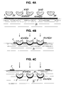
- a plurality of the objects W may be forcedly immersed in the liquid while being spaced from each other at predetermined intervals, as shown in Figs. 4A to 4C by way of example.
- the transfer film F is ultimately cut near both ends of an arc of the rim element A2, resulting in a transfer printing pattern being formed by gradations on the rim element A2, wherein a ground pattern gradually appears on the rim element A2.
- reference numeral 34 designates film extension members formed to have substantially the same configuration as the objects W and arranged on both sides of the objects W.
- the film extension member 34 may be formed to have, for example, a screen-like configuration while being spaced from the object W at a substantially uniform interval outside an outer periphery of the object W.
- Such liquid pressure transfer printing may be carried out according to a procedure disclosed in Japanese Patent Application Laid-open Publication No. 117326/1995 entitled “Liquid Pressure Transfer Method", of which the disclosure is herein incorporated by reference.
- the liquid pressure transfer printing is carried out on the rim element A2 for each of the front side members 41a and 42a of the long and short rim portions 41 and 42.
- the liquid pressure transfer printing may be carried out on the whole steering wheel which has been subjected to the rim assembling step 14.
- the liquid pressure transfer printing can be made on the rear side members 41b and 42b of the long and short rim portions 41 and 42 which are difficult to observe from a driver's seat as well.
- a joint between both ends of the transfer film F is desirably located at a position which permits the joint to be out of sight of a driver's seat.
- Such liquid pressure transfer printing may be practiced according to a procedure disclosed in Japanese Patent Application Laid-Open Publication No. 329498/1998 entitled “Method for Manufacturing Steering Wheel Having Liquid pressure Transfer Printing Applied Thereto", of which the disclosure is herein incorporated by reference.
- the liquid pressure transfer printing step 15 permits the print to be exclusively applied to the front side members 41a and 42a of the long and short rim portions 41 and 42 which are observable from a driver's seat in a state where the steering wheel 1 is mounted in a vehicle. Also, in the illustrated embodiment, the step 15 permits formation of the transfer printing pattern by gradations wherein the transfer ink layer Q is gradually reduced in thickness toward the innermost and outermost peripheral portions of the rim section 4, resulting in the ground pattern gradually appearing.
- the flow pattern acting as the ground pattern is observed through the transfer pattern superposed on the ground pattern, so that the flow pattern or ground pattern and the transfer pattern synergistically cooperate with each other to create a woodgrain pattern.
- the thus-created woodgrain pattern is rendered gradually thin toward the rear side of the steering wheel which is out of sight of a driver. Whereas, the feel of wood on the rear side of the steering wheel is not deteriorated, resulting in the feel being substantially equal to that of natural wood.
- the joint or boundary region of the transfer pattern is defined at each of the innermost peripheral portion and outermost peripheral portion of the rim section 4.
- the boundary may be defined at a more rearward position.
- the method may be used for manufacturing an article for a vehicle having a flat shape, such as a cover plate for a power window switch or the like.
- an extruded plate is subjected to re-heating, rough bending, fitting in a die, pressing and the like in turn in a similar manner as described above.
Landscapes
- Engineering & Computer Science (AREA)
- Mechanical Engineering (AREA)
- Chemical & Material Sciences (AREA)
- Combustion & Propulsion (AREA)
- Transportation (AREA)
- Steering Controls (AREA)
- Injection Moulding Of Plastics Or The Like (AREA)
- Printing Methods (AREA)
- Extrusion Moulding Of Plastics Or The Like (AREA)
Abstract
Description
- This invention relates to a steering wheel for a vehicle, and more particularly to a steering wheel having both an appearance and feel of wood like that of natural wood and a method for manufacturing the same.
- A steering wheel for a vehicle is kept grasped by a driver during driving of the vehicle, thus, it is essential that the steering wheel not only exhibits a satisfactory appearance but is pleasant to the touch. Such pleasant touch means that the steering wheel does not exhibit an excessively smooth feel, a rough feel or a tacky feel. Also, it means that the steering wheel is not slippery, excessively hot or excessively cold. Such requirements for the pleasant touch are sufficiently satisfied by a conventional wooden steering wheel. Unfortunately, the wooden steering wheel causes distortion peculiar to a natural tree material due to a variation in ambient temperature, irradiation of direct sun beams thereon, a variation in ambient moisture and the like. This results in peeling of the wooden steering wheel, cracking thereof and the like. Also, the wooden steering wheel is not suitable for mass production because currently there is a shortage of natural wood material available.
- In view of the above, a steering wheel which is constructed so as to have the feel of wood like that of natural wood has been recently substituted for the wooden steering wheel in the market. Such a substitute steering wheel is generally manufactured by forming a suitable synthetic resin material into a rim section for the steering wheel by molding and applying the appearance of wood to the rim section. Such application of the appearance of wood is carried out using either techniques of providing an appearance of the thus-formed rim section with the feel of wood or techniques of subjecting a synthetic resin material which has woodmeal previously added thereto to injection molding to form a rim section. The latter techniques provide the steering wheel with not only the feel of wood but an appearance of wood due to a stream or flow pattern formed on the rim section during the injection molding.
- However, the former techniques are disadvantageous in that printing on the rim section carried out after the above-described molding fails to provide the steering wheel with a satisfactory feel of wood, although it provides the steering wheel with an appearance which is very similar to that of natural wood. Also, the latter techniques of injection molding the synthetic resin material having the woodmeal added thereto fail to permit the steering wheel to exhibit a satisfactory appearance of wood although they provide it with an improved feel of wood. More particularly, in the latter techniques, the flow pattern formed during the injection molding is excessively emphasized due to foaming of moisture held in the woodmeal. Also, the latter techniques cause discolouration of the woodmeal due to generation of heat from the woodmeal by high shearing. The flow pattern formed during the injection molding is principally based on a curved flow pattern formed by a phenomenon that synthetic resin materials injected from several gates freely flow in a mold cavity and then merge with each other. In other words, the curved flow pattern is formed by spreading of the synthetic resin materials from the gates and swirling of the materials in places. If such spreading and swirling of the synthetic resin materials permitted the curved flow pattern to be finely formed, the steering wheel would be provided with an appearance of high quality in imitation of precious wood which provides a pretty grain pattern of wood, such as a circular grain pattern, a grape-like grain pattern, or the like as seen in a zelkova tree, a mulberry tree, a camphor tree, a jujube tree or the like. Unfortunately, the techniques currently practiced fail to provide the steering wheel with the feeling of high-grade wood in appearance.
- The present invention has been made in view of the foregoing disadvantages of the prior art and as a result of the inventors' effort of developing a steering wheel which has both an appearance and feel of wood which is substantially equal to that of natural wood and a method for manufacturing the same. In a steering wheel of the present invention, an appearance of wood which is substantially equal to or the same as that of natural wood does not refer to an appearance of precious wood having a pretty grain pattern of wood, such as a circular grain pattern, a grape-like grain pattern, or the like. Rather, it refers to a general woodgrain such as a straight grain or a cross grain. In the present invention, such a woodgrain is formed on a rim section of the steering wheel while defining a flow pattern in a circumferential direction of the rim section, to thereby give the impression that the flow pattern is formed by a sliced veneer.
- Accordingly, it is an object of the present invention to provide a steering wheel which is capable of giving the impression that it is formed thereon with a woodgrain pattern in a manner to extend in a circumferential direction thereof, resulting in the steering wheel having both an appearance and feel of wood which is substantially equal to that of natural wood.
- It is another object of the present invention to provide a method for manufacturing a steering wheel which is capable of ensuring reliable and inexpensive mass-production of a steering wheel which gives the impression that the steering wheel is formed thereon with a woodgrain pattern in a manner to extend in a circumferential direction thereof, resulting in the steering wheel having both an appearance and feel of wood which is substantially equal to that of natural wood.
- In accordance with one aspect of the present invention, a steering wheel is provided. The steering wheel includes a rim section having a core incorporated therein. The rim section is constituted by rim elements made of a thermosoftening synthetic resin material to which woodmeal is added, resulting in the rim section being formed thereon with a flow pattern. The rim elements are each re-shaped from a straight rod-like configuration into an arcuate configuration in conformity to a curvature of the core and mounted on the core, so that the flow pattern may be transformed into an annular flow pattern.
- Such construction of the present invention permits the steering wheel to give the impression that the steering wheel is formed thereon with a woodgrain pattern in a manner to extend in a circumferential direction thereof, so that it may have both an appearance and feel of wood which is substantially equal to that of natural wood.
- In a preferred embodiment of the present invention, the thermosoftening synthetic resin material has a colour pigment added thereto so that the flow pattern is formed in an annular flow pattern which has a clear woodgrain emphasized by the colour pigment added. Thus, the steering wheel of such a preferred embodiment of the present invention gives the strong impression that it is formed thereon with a woodgrain pattern as if it is formed by a sliced veneer.
- In a preferred embodiment of the present invention, the rim section is formed thereon with an uneven portion to facilitate holding, in such a manner that the flow pattern is transformed into the annular flow pattern while preventing the thus-formed annular flow pattern from being disordered by the unevenness. Thus, the steering wheel of such an embodiment of the present invention gives the strong impression that it is formed thereon with a woodgrain pattern as if the unevenness on the steering wheel is formed by cutting of natural wood.
- In accordance with another aspect of the present invention, a method for manufacturing a steering wheel is provided. The method includes the steps of extruding a thermosoftening synthetic resin to which woodmeal is added to prepare a pair of straight rod-like rim elements, bending the straight rod-like rim elements into an arcuate shape in conformity to a curvature of a core while keeping the rim elements softened, and mounting the rim elements thus bent on the core while interposing the core therebetween.
- Thus, the method permits mass-production of a steering wheel which gives the impression that it is formed thereon with a woodgrain pattern in a manner to extend in a circumferential direction thereof, resulting in the steering wheel having both an appearance and feel of wood which is substantially equal to that of natural wood.
- In a preferred embodiment of the present invention, the extruding step is carried out using a nozzle formed to have a semicircular shape in section having an arc section formed substantially in conformity to an arcuate shape which is a half of a sectional configuration of a rim section of a finished steering wheel and which is defined at an outermost portion of the rim section and a chord section projectingly provided with a core corresponding section which is formed substantially in conformity to a half of a sectional configuration of the core, resulting in the rim elements being prepared in the form of a straight rod-like shape.
- Such construction permits mounting of the rim elements on the core to be carried out in the subsequent step, to thereby prevent disorder of the flow pattern in the circumferential or annular direction during re-shaping of the rim elements.
- In a preferred embodiment of the present invention, the bending step is carried out using a regulating die formed thereon with projections for forming an uneven portion for holding and a forcing die, wherein the straight rod-like rim elements are each softened by re-heating to be roughly bent into an arcuate shape and then fitted in the regulating die, then pressed by means of the forcing die, during which the regulating die and forcing die cooperate with each other to define an arcuate cavity having a vacant region defined at each of opposite ends thereof in a longitudinal direction thereof. Thus, in at least preferred embodiments the method of the present invention attains satisfactory re-shaping of the rim elements while effectively preventing disorder of the flow pattern in the circumferential direction.
- In a preferred embodiment of the present invention, wherein the pair of rim elements each include a front side rim element observable from a driver's seat and a rear side rim element opposite to the front side rim element, the mounting step is carried out by mounting the front and rear side rim elements on the core while adhesively joining the front and rear rim elements to each other.
- Such construction permits joints between the front side rim element and the rear side rim element to be positioned at an outermost periphery of the rim section and an innermost periphery thereof, so that the joints may be substantially out of sight of a driver. Also, it permits mounting of the rim elements on the core to be attained with increased strength.
- In a preferred embodiment of the present invention, the pair of rim elements each include an inner peripheral side rim element and an outer peripheral side rim element opposite to the front side rim element. The mounting step is carried out by mounting the inner and outer peripheral side rim elements on the core while adhesively joining the inner and outer peripheral side rim elements to each other. This causes joints between both rim elements to appear on a front side of the rim section which is observable from a driver's seat and a rear side thereof which is not observable from the driver's seat. Thus, when it is desired to improve aesthetic properties of the rim section and therefore the steering wheel, it is merely required to cover the front side joint with a molding or the like.
- In a preferred embodiment of the present invention, the mounting step includes mounting a cover member, such as a molding, an ebony-patterned member, or the like on a joint between the rim elements. This not only effectively hides the joint but provides the steering wheel with a decorative effect. Also, it permits joining between the rim elements to be strengthened.
- In a preferred embodiment of the present invention, the thermosoftening synthetic resin material which is fed in the extruding step is constituted by a combination of pellets having the woodmeal kneadingly incorporated therein and pellets having a colour pigment added thereto as well as the woodmeal and exhibiting a colour different from that of the former pellets. This permits mass-production of a steering wheel which gives the impression that it is formed thereon with a woodgrain pattern as if it is formed by a sliced veneer.
- In a preferred embodiment of the present invention, the method further includes the step of applying a coating to the rim elements, wherein the coating is applied to a front side of the rim elements observable from a driver's seat. This minimizes a stain on the front side of the rim section while preventing the feel of wood on the rear side thereof from being deteriorated.
- In a preferred embodiment of the present invention, the method further includes the step of carrying out liquid pressure transfer printing of the rim elements, wherein the transfer print is applied to a front side of the rim elements observable from a driver's seat. Also, the liquid pressure transfer printing is carried out so as to permit formation of a transfer printing pattern by gradations on the rim elements wherein a transfer ink layer is gradually reduced in thickness toward a rear side of the rim elements, whereby a ground pattern gradually appears on the rim elements.
- This minimizes a stain of the front side of the rim section while preventing the feel of wood on the rear side from being deteriorated. Also, it permits the flow pattern and transfer pattern to cooperate with each other to provide the rim section with a high-grade appearance which gives the impression of a pretty grain pattern of precious wood.
- These and other objects and many of the attendant advantages of the present invention will be readily appreciated as the same becomes better understood by reference to the following detailed description of preferred embodiments of the invention when considered in connection with the accompanying drawings; wherein:
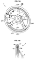
- Fig. 1A is a perspective view showing an embodiment of a steering wheel according to the present invention;
- Fig. 1B is a fragmentary sectional view of the
steering wheel of Fig. 1A taken along
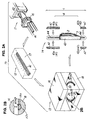
line 1B-1B; - Fig. 2A is a schematic view showing steps in a method for manufacturing a steering wheel according to an embodiment of the present invention by way of example;
- Fig. 2B is an enlarged sectional view of
part 2B in Fig. 2A; - Fig. 3A is a schematic view showing a liquid pressure transfer printing step in a method for manufacturing a steering wheel according to an embodiment of the present invention, by way of example;
- Fig. 3B is a plan view showing rim elements mounted on a carrier unit;
- Figs. 4A to 4C are schematic views showing a liquid pressure transfer printing step which permits formation of a transfer printing pattern by gradations, respectively;
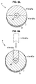
- Figs. 5A and 5B each are an enlarged sectional view showing a rim element which has been subjected to liquid pressure transfer printing, to thereby be provided thereon with the transfer printing pattern by gradations;
- Fig. 6 is a sectional view of a die for extruding rim elements for a rim section, showing a configuration of a nozzle provided on the die;
- Fig. 7A is a side elevation view partially in section showing another embodiment of a steering wheel according to the present invention;
- Fig. 7B is an exploded sectional view of
part 7B in Fig. 7A; and - Fig. 7C is an exploded sectional view showing another arrangement similar to that of Fig. 7B.
-
- Now, preferred embodiments of the present invention will be described hereinafter with reference to the accompanying drawings. The following description will be first made of a steering wheel according to a first illustrated embodiment of the present invention. Then, manufacturing of the steering wheel in accordance with an embodiment of the present invention will be described. In the following description, a starting material of which a rim section for the steering wheel is made will be referred to as a raw material A0, a straight rod-like member formed of the raw material A0 by extrusion will be referred to as a straight rim element A1, and an arcuate member formed by bending the rim element A1 will be referred to as an arcuate rim element A2.
- Referring first to Figs. 1A and 1B, an embodiment of a steering wheel according to the present invention is illustrated. A steering wheel of the illustrated embodiment which is generally designated by reference numeral 1 generally includes a
boss section 2 acting as a centre of rotational movement of the steering wheel 1, spokesections 3 arranged so as to radially extend from theboss section 2, and arim section 4 connected to a distal end of each of thespoke sections 3 and formed to have an annular shape. Therim section 4 is constituted by along rim portion 41 of an elongated arcuate shape (positioned on an upper side in Fig. 1A), ashort rim portion 42 of a short arcuate shape (positioned on a lower side in Fig. 1A), and two grip portions 43 (positioned on both lateral sides in Fig. 1A) for connecting thelong rim portion 41 andshort rim portion 42 to each other therethrough. Therim section 4 has a core 44 incorporated therein, which may be formed by bending a metal rod into an annular shape by way of example. Thelong rim portion 41,short rim portion 42 andgrip portions 43 are mounted on thecore 44, to thereby provide therim section 4. In the illustrated embodiment, thespoke sections 3 may be made of metal and welded directly to thecore 44, so that thegrip portions 43 may be formed of flexible urethane by insert molding so as to extend over bothcore 44 and spokesections 3. Then, thelong rim portion 41 andshort rim portion 42 are mounted on the core 44 on which thegrip portions 43 are thus molded, resulting in a so-called combination steering wheel being provided. Alternatively, thegrip portions 43 may each be mounted therein with a rim element A2 of an arcuate shape. - In the illustrated embodiment, the
long rim portion 41 andshort rim portion 42 are each constituted by two halves formed so as to extend in a longitudinal direction thereof, resulting in interposedly holding the core 44 therebetween. The two halves are adhesively joined to each other to provide each of thelong rim portion 41 andshort rim portion 42. More specifically, supposing that thelong rim portion 41 andshort rim portion 42 are mounted in a vehicle, a front side member of thelong rim portion 41 which is observable from a driver's seat is designated by reference character 41a and that of theshort rim portion 42 observable therefrom is 42a. Also, rear side members of thelong rim portion 41 andshort rim portion 42 which are not observable from the driver's seat or are out of sight of the driver are designated byreference characters rear side members 41a and 41b of thelong rim portion 41 are each formed to have a substantially semicircular shape in section by way of example. This is true of the front andrear side members short rim portion 42. The front and rear side members of the long andshort rim portions core holding recess 45 in a manner to extend in a longitudinal direction thereof. Thus, in the illustrated embodiment, thelong rim portion 41 andshort rim portion 42 are each constituted by the two front and rear side members joined to each other. Alternatively, the long andshort rim portions front side members 41a and 42a of the long andshort rim portions core 44 is received therein from a side of a rear surface thereof. Also, therear side member 41b of thelong rim portion 41 and therear side member 42b of theshort rim portion 42 are each formed to have a thickness substantially equal to a thickness of the core 44, to thereby close thecore holding recess 45. - Further, in the illustrated embodiment, it is not necessarily required that the
rim section 4 is constituted of such front and rear side members as described above. It may be configured as shown in Figs. 7A and 7B. More particularly, thelong rim portion 41 is constituted of two halves or an innerperipheral side member 41c and an outer peripheral side member 41d and theshort rim portion 42 is constituted of two halves or an innerperipheral side member 42c and an outerperipheral side member 42d. Such configuration of Figs. 7A and 7B causes joints between the innerperipheral side member 41c (42c) and the outer peripheral side member 41d (42d) to appear on both a front position observable from the driver's seat and a rear position out of sight of the driver. Thus, acover member 46 such a molding, an element formed thereon with an ebony-like pattern or the like may be attached to at least the front joint to hide it from view. Such attachment of thecover member 46 to the joints may be likewise applied to therim section 4 constituted of the front side member and rear side member as described above. Attachment of thecover member 46 to the joints of therim section 4 may be carried out by forming each of the inner and outer peripheral side members or front and rear side members with a recess and interposedly fitting both ends of thecover member 46 formed to have a substantially C-shape into the respective recesses of the side members. This also ensures reinforcement of therim section 4. In Figs. 7A to 7C,reference numerals rim section 4. - Now, a raw material A0 for the
long rim portion 41 andshort rim portion 42 will be described. The raw material A0 essentially consists of a thermoplastic or thermosoftening synthetic resin material such as AAS (acrylonitrile acrylic styrene) resin, AES (acrylonitrile- (ethylene-propylene-diene terpolymer)-styrene) resin, ABS (acrylonitrile butadiene styrene) resin or the like. In addition to the synthetic resin material, the raw material A0 contains woodmeal in an amount of tens of percent added to the resin material. By way of example, the raw material may be constituted by AAS (acrylonitrile acrylic styrene) resin acting as a main component and woodmeal of 60 µm in average particle diameter in an amount of 20% which has an inorganic pigment such as titanium oxide or the like incorporated therein. - The woodmeal referred to herein includes not a mere wood powder (wood shavings) but a mixture of the woodmeal with an inorganic pigment such as titanium oxide, iron oxide, cadmium yellow, carbon black or the like added thereto so as to permit the woodmeal to withstand an elevated temperature during the molding. For this purpose, a product commercially available under "TECHNOMATERIAL" (trademark) from MISAWA HOMES CO., LTD. may be suitably used. When such woodmeal having titanium oxide incorporated therein is kneaded into the main component or synthetic resin material, the raw material exhibits a colour within a range between light brown and a flesh colour, because titanium oxide has a white colour. Also, addition of the woodmeal having iron oxide or an inorganic pigment such as cadmium yellow, carbon black or the like incorporated thereinto to the synthetic resin material permits the raw material to exhibit a different appearance colour, such as dark brown or the like, because the iron oxide or the inorganic pigment has a colour other than a white colour.
- The amount of each of the synthetic resin material and woodmeal added thereto may be suitably varied depending on various conditions such as molding conditions, a type of the synthetic resin material used, compatibility with the synthetic resin material or the inorganic pigment, and the like.
- Now, manufacturing of the steering wheel 1 thus constructed will be described with reference to a
manufacturing process 10 shown in Fig. 2A. Theprocess 10 generally includes an extrudingstep 11, a bendingstep 13 and arim assembling step 14. Also, theprocess 10 includes a thermally softeningstep 12 practiced as a pretreatment prior to the bendingstep 13. In addition, theprocess 10 may optionally include a liquid pressuretransfer printing step 15 and the like. - In the extruding
step 11, the raw material A0 is melted by heating in a cylinder of an extruding machine or the like known in the art and then extruded through a die nozzle or a forming die, resulting in the straight rim element A1 which has a desired shape in section being obtained. Feeding of the raw material A0 to the extruding machine is not carried out in such a manner that the synthetic resin material and woodmeal are fed at a predetermined compounding ratio directly to the extruding machine. Rather, pellets formed by kneading the synthetic resin material and woodmeal with each other are fed to the extruding machine. Desirably, plain-coloured pellets made of "TECHNOMATERIAL" constituted by incorporating titanium oxide into woodmeal and coloured pellets made of "TECHNOMATERIAL" constituted by incorporating a colour pigment into the woodmeal so as to exhibit a brown colour are fed at a compounding ratio of 3 : 1 to the extruding machine. When the pellets thus fed to the extruding machine are extruded from the extruding machine while being kept from being completely uniformly mixed together, a streak-like flow pattern on which light and shade alternately appear is permitted to be formed in a straight streak-like manner on the straight rim element A1. Of course, use of either the plain-coloured pellets or the coloured pellets likewise permits a straight streak-like flow pattern to be somewhat formed on the straight rim element A1, because the woodmeal is a natural material, to thereby be kept from fully homogenized in the resin material and the pellets are extruded from the extruding machine under an extrusion pressure of the machine. The flow pattern thus formed creates a woodgrain pattern such as a straight grain pattern or a cross grain pattern, to thereby permit the rim element A1 to exhibit an appearance of wood. - In the illustrated embodiment, the straight rim element A1 constitutes the front side member 41a and
rear side member 41b of thelong rim portion 41 and thefront side member 42a andrear side member 42b of theshort rim portion 42 later. The straight rim element A1 may be formed to have a substantially semicircular shape in section of which a central portion is recessed. More specifically, as shown in Fig. 6, the straight rim element A1 is desirably extruded by means of a forming die or a die 16 projectingly provided with a nozzle formed to have a configuration in section including an arcuate section 16a which substantially conforms to an arcuate shape in section obtained by dividing the thickest portion (outermost portion) of thelong rim portion 41 orshort rim portion 42 of a finished steering wheel into a front side half and a rear side half, as well as achord section 16b which is projectingly provided with acore corresponding section 16c formed to have a configuration substantially conforming to a half of a sectional configuration of thecore 44. When the straight rim element A1 is thus formed by extrusion using the nozzle-equippeddie 16 or the forming die, disorder or disturbance of the flow pattern which contributes to creation of a woodgrain pattern such as a straight grain or a cross grain is minimized during the subsequent re-shaping step. Fig. 6 shows a section of the die provided with the nozzle for extrusion of therear side members - In the thermally softening
step 12, the straight rim element A1 for the front andrear side members 41a and 41b of thelong rim portion 41 and the front andrear side members short rim portion 42 which has been thus prepared in the extrudingstep 11 is received in, for example, athermostatic oven 17 or the like, wherein the straight rim element A1 is heated to a temperature of about 100 to 120°C, resulting in the rim element A1 being softened. When the preceding extrudingstep 11 andsubsequent bending step 13 are carried out at the same treatment speed, the rim element A1 immediately after extruded in the extrudingstep 11 still holds softness to a degree, so that it may be transferred directly to the bendingstep 13 without being subjected to the thermally softeningstep 12. However, in view of a difference in treatment speed between the preceding extrudingstep 11 and thesubsequent bending step 13 and efficient operation of whole equipment, it is desirable that the rim elements A1 as extruded from the extrudingstep 11 are permitted to be solidified by cooling while being kept in a straight rod-like shape and then cut to a predetermined even length or collected in a predetermined lot size, followed by feeding to the bendingstep 13. In this instance, the rim element A1 once solidified in the straight rod-like shape is exposed to the thermally softeningstep 12, resulting in the rim element A1 being softened to a degree which permits it to be re-shaped in the subsequent step. A heating temperature and a period of heating time each may be merely set at a level which permits re-shaping of the rim element A1. Excessive heating of the rim element loses meaning of using the above-described die provided with the nozzle of a fine configuration. - In the bending
step 13, the rim element A1 kept softened is subjected to re-shaping, resulting in the rim element A1 being transformed from the straight rod-like shape into an arcuate shape conforming to a curvature of thecore 44. In the illustrated embodiment, in the bendingstep 13, the straight rim element A1 kept softened is roughly bent into an arcuate shape by hand. Then, the rim element A1 is fitted in a regulatingdie 18 and then a forcingdie 19 is forced against the regulating die 18, resulting in forming the arcuate rim element A2. The regulating die 18 and forcing die 19 are so configured that a cavity formed by cooperation of the dies 18 and 19 is formed to have the same sectional configuration as that of thelong rim portion 41 orshort rim portion 42 of a finished steering wheel. Removal of the arcuate rim element A2 from the dies 18 and 19 is desirably carried out after it is solidified to a degree by cooling. For this purpose, the dies may be provided with any suitable heating and cooling means. Thus, removal of the rim element A2 from the dies is carried out so as to prevent deformation of the rim element after the removal while taking manufacturing efficiency into consideration. - In general, a steering wheel is formed on a rear side thereof with a non-slip uneven portion for facilitating holding of the steering wheel. In the illustrated embodiment, formation of such unevenness A2a may be carried out simultaneously with re-shaping of the rim element into a general arcuate configuration during the bending
step 13 wherein the straight rim element A1 is transformed into the arcuate rim element A2. - In the bending
step 13, transformation of the straight rim element A1 into the arcuate rim element A2 causes flowing of the material due to some difference in three-dimensional geometric volume between the straight rim element A1 and the arcuate rim element A2. Also, formation of the non-slip unevenness A2a described above causes a variation in section of the rim element, leading to flow of the material. Thus, in order to ensure that the flow pattern which contributes to creation of a woodgrain pattern such as a straight grain or a cross grain is prevented from being disordered by the material flow, the illustrated embodiment is so configured that the arcuate cavity defined by cooperation between the regulatingdie 18 and the forcingdie 19 provides avacant region 20 on each of opposite ends defined in a longitudinal direction thereof, to thereby permit the material to escape to thevacant regions 20. Also, in the illustrated embodiment, the regulating die 18 formed withprojections 18a for forming the non-slip unevenness A2a on the rim element A2 is used for pressing the arcuate rim element A2 which is configured to conform to the arcuate shape in section obtained by dividing the thickest portion (outermost portion) of thelong rim portion 41 orshort rim portion 42 of a finished steering wheel into the front side half and rear side half. Thus, the unevenness A2a which facilitates holding is formed by merely forcing theprojections 18a of the regulating die 18 against the rim element, to thereby minimize disorder of the flow pattern. - Thus, the bending
step 13 permits the straight streak-like flow pattern formed on the straight rim element A1 in the extrudingstep 11 to be transformed into an arcuate flow pattern along the arcuate configuration of the arcuate rim element A2 without being disordered, so that the rim element A2 may exhibit an appearance of wood created by the woodgrain pattern. - An assembly preparation step may be carried out before the arcuate rim element A2 thus bent is mounted on the
core 44. More specifically, for example, when the arcuate rim element A2 for each of thelong rim portion 41 andshort rim portion 42 is formed to have a length larger than a predetermined one in the preceding step, the assembly preparation step is carried out in order to cut it into the predetermined length. Also, the step may be carried out for making edges of the rim element thus cut uniform or subjecting an arcuate surface of the rim element to light grinding. Further, it may take place for applying a coating such as a clear coating or the like to the surface of the rim element. The surface grinding permits removal of a skin layer which tends to be formed on the surface of the rim element therefrom, to thereby expose the woodmeal, so that the finished product or steering wheel 1 may exhibit the feel of wood. Of course, when a coating such as a clear coating is applied to the whole steering wheel 1, applying of the coating is not carried out in the assembly preparation step. Instead, applying of the coating may be practiced after the rim assembling step of mounting the element A2 on the core. In the assembly preparation step, the coating on the rim element A2 for each of thelong rim portion 41 andshort rim portion 42 permits the front side thereof to have been burnished and the rear side thereof to be kept exhibiting the feel of wood. - The
rim assembling step 14 briefly described above is to mount pairs of the arcuate rim elements A2 bent into an arcuate shape on the core 44 while interposing the core 44 between the rim elements A2. In the first illustrated embodiment, the front side member 41a andrear side member 41b of thelong rim portion 41 are joined to each other and to the core 44 by means of an adhesive applied to thechord section 16b andcore corresponding section 16c thereof. Likewise thefront side member 42a andrear side member 42b of theshort rim portion 42 are joined to each other and to the core 44 using the adhesive. The front side members and rear side members are kept clamped until adhesive joining therebetween is attained. Then, a portion of the adhesive projecting from between the members and solidifying is removed by grinding, resulting in the finished steering wheel 1 being obtained. - In the steering wheel 1 thus manufactured, the flow pattern on each of the
long rim portion 41 andshort rim portion 42 each constituted by the rim elements A2 may be observed in the form of an annular flow pattern extending along an annular configuration of the steering wheel, so that light and shade alternately appear in the flow pattern. This permits a woodgrain pattern giving the impression that it is formed by a sliced veneer to appear on the steering wheel 1, so that it may satisfactorily exhibit an appearance of wood. - In the first illustrated embodiment, the
rim section 4 of the steering wheel 1 is divided into the front side and rear side, each of which is constituted by the rim element A2. Such construction permits joints between the front side member and the rear side member to be positioned at the innermost peripheral portion of therim section 4 and the outermost peripheral portion thereof, resulting in the joints being conveniently out of sight of a driver. In general, such joints are fine to a degree of rendering it substantially impossible to recognize it at a glance. However, in order to hide the joints and provide a specific decoration effect, acover member 46 such as a molding, an ebony-patterned element or the like may be mounted thereon. In this instance, a second illustrated embodiment, as shown in Fig. 7C, may be so configured that the rim elements for the front side member and rear side member are formed with recesses, respectively, and thecover member 46 of a C-shape is securely mounted on the joint while both ends of thecover member 46 are fitted in the respective recesses of the rim elements. Attachment of thecover member 46 to the rim elements A2 may be attained by any suitable means such as welding, fusion bonding, fitting or the like in addition to an adhesive. Mounting of thecover member 46 on the joints between the rim elements is advantageous when therim section 4 is constituted by an inner peripheral side member and outer peripheral side member. - The liquid pressure
transfer printing step 15 may be optionally practiced as required, like the clear coating step. The liquid pressuretransfer printing step 15 may be carried out on the whole steering wheel which has been just subjected to the rim assembly step of mounting the long rim portion and short rim portion on the core. Alternatively, it may be carried out on the arcuate rim element A2 which has been subjected to the bending step. The following description will be made on liquid pressure transfer printing carried out on the arcuate rim element A2. - The liquid pressure transfer printing may be practiced by means of a liquid pressure transfer apparatus designated by
reference numeral 30 in Fig. 3A. The liquidpressure transfer apparatus 30 generally includes atransfer bath 31, a transferfilm feed unit 32 and anobject carrier unit 33. Thetransfer bath 31 is fed therein with a transfer film F on which a suitable pattern such as a woodgrain pattern or the like is printed by means of the transferfilm feed unit 32. The transfer film F thus fed to thetransfer bath 31 is kept floated on a surface of a liquid in thebath 31. When the transfer film F is activated, resulting in it being rendered transferable, theobject carrier unit 33 is actuated to force an object W to which an ink pattern on the transfer film F is to be transferred against the transfer film F, so that the ink pattern on the transfer film F may be transferred to the object W. In this instance, the object W is constituted by the arcuate rim element A2 for each of thefront side members 41a and 42a constituting the front side of therim section 4 of the steering wheel 1. - In Fig. 3A, the object W is shown as if it is vertically downwardly lowered in the
transfer bath 31. Alternatively, the object W may be obliquely lowered by means of a conveyor of an inverted triangular configuration or a robot. Also, in the illustrated embodiment, the transfer film F is coated thereon with an activator and then fed to thetransfer bath 31. Alternatively, the illustrated embodiment may be so configured that the transfer film F is fed to thetransfer bath 31 and then coated thereon with a solvent or the like, resulting in the transfer film F being activated. Further, in illustrated embodiment, the transfer film F is continuously fed to thetransfer bath 31 in which the liquid is flowed. Alternatively, individual transfer films F which are in the form of a leaf may be fed one by one by hand to thetransfer bath 31 in which the liquid is kept stationary and then the object W is immersed in the liquid by hand. In addition, the object W is constituted by the arcuate rim element A2. The object W may be the straight rim element A1 which is not subjected to the bendingstep 13, as shown in Fig. 3B. - The liquid pressure transfer printing is desirably proceeded while permitting a transfer ink layer Q to be gradually reduced in thickness. For this purpose, a plurality of the objects W may be forcedly immersed in the liquid while being spaced from each other at predetermined intervals, as shown in Figs. 4A to 4C by way of example. This permits the transfer film F to be gradually reduced in thickness toward a chord of a section of the rim element A2. The transfer film F is ultimately cut near both ends of an arc of the rim element A2, resulting in a transfer printing pattern being formed by gradations on the rim element A2, wherein a ground pattern gradually appears on the rim element A2. In Figs. 3A and 3B,
reference numeral 34 designates film extension members formed to have substantially the same configuration as the objects W and arranged on both sides of the objects W. - When the liquid pressure transfer printing is to be carried out on a single object W or on the whole steering wheel which has been subjected to the rim assembling step, the
film extension member 34 may be formed to have, for example, a screen-like configuration while being spaced from the object W at a substantially uniform interval outside an outer periphery of the object W. Such liquid pressure transfer printing may be carried out according to a procedure disclosed in Japanese Patent Application Laid-open Publication No. 117326/1995 entitled "Liquid Pressure Transfer Method", of which the disclosure is herein incorporated by reference. - Also, in the illustrated embodiment, the liquid pressure transfer printing is carried out on the rim element A2 for each of the
front side members 41a and 42a of the long andshort rim portions rim assembling step 14. In this instance, the liquid pressure transfer printing, of course, can be made on therear side members short rim portions - The liquid pressure
transfer printing step 15, as shown in Fig. 5A, permits the print to be exclusively applied to thefront side members 41a and 42a of the long andshort rim portions step 15 permits formation of the transfer printing pattern by gradations wherein the transfer ink layer Q is gradually reduced in thickness toward the innermost and outermost peripheral portions of therim section 4, resulting in the ground pattern gradually appearing. On the front side of the steering wheel 1 which is observable from a driver's seat, the flow pattern acting as the ground pattern is observed through the transfer pattern superposed on the ground pattern, so that the flow pattern or ground pattern and the transfer pattern synergistically cooperate with each other to create a woodgrain pattern. The thus-created woodgrain pattern is rendered gradually thin toward the rear side of the steering wheel which is out of sight of a driver. Whereas, the feel of wood on the rear side of the steering wheel is not deteriorated, resulting in the feel being substantially equal to that of natural wood. - In the illustrated embodiment, the joint or boundary region of the transfer pattern is defined at each of the innermost peripheral portion and outermost peripheral portion of the
rim section 4. When thefront side members 41a and 42a of the long andshort rim portions rim assembling step 14, the boundary may be defined at a more rearward position. - Although preferred embodiments of the method of the present invention have been described above as related to the embodiments of a steering wheel, the method may be used for manufacturing an article for a vehicle having a flat shape, such as a cover plate for a power window switch or the like. For providing such an article, an extruded plate is subjected to re-heating, rough bending, fitting in a die, pressing and the like in turn in a similar manner as described above.
- While preferred embodiments of the invention have been described with a certain degree of particularity with reference to the drawings, obvious modifications and variations are possible in light of the above teachings. It is therefore to be understood that within the scope of the appended claims, the invention may be practiced otherwise than as specifically described.
Claims (14)
- A steering wheel (1) comprising:a rim section (4) having a core (44) incorporated therein;said rim section (4) being constituted by rim elements (A2) made of a thermosoftening synthetic resin material to which woodmeal is added, resulting in said rim section (4) being formed thereon with a flow pattern;said rim elements (A2) each being re-shaped from a straight rod-like configuration into an arcuate configuration in conformity to a curvature of said core (4) and mounted on said core (4), so that the flow pattern may be transformed into an annular flow pattern.
- A steering wheel (1) as defined in claim 1, wherein said thermosoftening synthetic resin material has a color pigment added thereto so that the flow pattern is formed in an annular flow pattern which has a clear woodgrain emphasized by said added color pigment.
- A steering wheel (1) as defined in claim 2 or 3, wherein said rim section (4) is formed thereon with an uneven portion (A2a) to facilitate holding, in such a manner that the flow pattern is transformed into the annular flow pattern while preventing the thus-formed annular flow pattern from being disordered by said unevenness (A2a).
- A method for manufacturing a steering wheel (1) comprising the steps of:extruding a thermosoftening synthetic resin to which woodmeal is added to prepare a pair of straight rod-like rim elements (A1);bending the straight rod-like rim elements (A1) into an arcuate shape in conformity to a curvature of a core (44) while keeping the rim elements (A1) softened; andmounting the rim elements (A2) thus bent on the core (44) while interposing the core (44) therebetween.
- A method as defined in claim 4, wherein said extruding step is carried out using a nozzle formed to have a semicircular shape in section having an arc section (16a) formed substantially in conformity to an arcuate shape which is a half of a sectional configuration of a rim section (4) of a finished steering wheel (1) and which is defined at an outermost portion of the rim section (4) and a chord section (16b) projectingly provided with a core corresponding section (16c) which is formed substantially in conformity to a half of a sectional configuration of the core (44), resulting in the rim elements (A2) being prepared in the form of a straight rod-like shape.
- A method as defined in claim 4 or 5, wherein said bending step is carried out using a regulating die (18) formed thereon with projections (18a) for forming an uneven portion to facilitate holding and a forcing die (19); andthe straight rod-like rim elements (A1) are each softened by re-heating to be roughly bent into an arcuate shape and then fitted in the regulating die (18), then pressed by means of the forcing die (19), during which the regulating die (18) and forcing die (19) cooperate with each other to define an arcuate cavity having a vacant region (20) defined at each of opposite ends thereof in a longitudinal direction thereof.
- A method as defined in claim 4, 5 or 6, wherein said pair of rim elements (A2) each include a front side rim element (41a, 42a) observable from a driver's seat and a rear side rim element (41b, 42b) opposite to the front side rim element (41a, 42a); andsaid mounting step is carried out by mounting the front and rear side rim elements (41a, 42a, 41b, 42b) on the core (44) while adhesively joining the front and rear rim elements (41a, 42a, 41b, 42b) to each other.
- A method as defined in claim 4, 5 or 6, wherein said pair of rim elements each include an inner peripheral side rim element (41c, 42c) and an outer peripheral side rim element (41d, 42d) opposite to the front side rim element (41c, 42c); andsaid mounting step is carried out by mounting the inner and outer peripheral side rim elements (41c, 42c, 41d, 42d) on the core (44) while adhesively joining the inner and outer peripheral side rim elements (41c, 42c, 41d, 42d) to each other.
- A method as defined in any of claims 4, 7 and 8 wherein said mounting step includes mounting a cover member (46) on a joint between the rim elements (41c, 42c, 41d, 42d).
- A method as defined in any of claims 4 to 9, wherein the thermosoftening synthetic resin material which is fed in the extruding step is constituted by a combination of pellets having the woodmeal kneadingly incorporated therein and pellets having a color pigment added thereto as well as the woodmeal and exhibiting a color different from that of the former pellets.
- A method as defined in any of claims 4 to 10, further comprising the step of applying a coating to the rim elements (A2), the coating being applied to a front side of the rim elements (A2) observable from a driver's seat.
- A method as defined in any of claims 4 to 11, further comprising the step of carrying out liquid pressure transfer printing on the rim elements (A2) ;
wherein the transfer print is applied to a front side of the rim elements (A2) observable from a driver's seat; andthe liquid pressure transfer printing is carried out so as to permit formation of a transfer printing pattern by gradations on the rim elements (A2) wherein a transfer ink layer (Q) is gradually reduced in thickness toward a rear side of the rim elements (A2), whereby a ground pattern gradually appears on the rim elements (A2). - A method of manufacturing a shaped wood-effect article comprising the steps of:extruding a thermosoftening synthetic resin to which woodmeal is added to prepare an extruded element (A1) ;bending the extruded element (A1) whilst softened into a desired shape; andcooling the element (A2) in said desired shape.
- A wood-effect article manufactured according to the method of claim 13 having a wood effect flow pattern formed by said bending.
Applications Claiming Priority (4)
| Application Number | Priority Date | Filing Date | Title |
|---|---|---|---|
| JP11091299 | 1999-04-19 | ||
| JP11091299 | 1999-04-19 | ||
| JP11225315A JP2001001910A (en) | 1999-04-19 | 1999-08-09 | Steering wheel and its manufacture |
| JP22531599 | 1999-08-09 |
Publications (2)
| Publication Number | Publication Date |
|---|---|
| EP1046566A2 true EP1046566A2 (en) | 2000-10-25 |
| EP1046566A3 EP1046566A3 (en) | 2002-11-13 |
Family
ID=26450429
Family Applications (1)
| Application Number | Title | Priority Date | Filing Date |
|---|---|---|---|
| EP00301594A Withdrawn EP1046566A3 (en) | 1999-04-19 | 2000-02-29 | Steering wheel and method for manufacturing same |
Country Status (9)
| Country | Link |
|---|---|
| US (1) | US20030075003A1 (en) |
| EP (1) | EP1046566A3 (en) |
| JP (1) | JP2001001910A (en) |
| KR (1) | KR100545513B1 (en) |
| CN (1) | CN1144710C (en) |
| CA (1) | CA2299647C (en) |
| ID (1) | ID25577A (en) |
| MY (1) | MY135413A (en) |
| TW (1) | TW466167B (en) |
Cited By (3)
| Publication number | Priority date | Publication date | Assignee | Title |
|---|---|---|---|---|
| KR100545513B1 (en) * | 1999-04-19 | 2006-01-24 | 가부시키가이샤 큐빅 | Streering wheel and method for manufacturing same |
| JP2009533274A (en) * | 2006-04-12 | 2009-09-17 | グルポ エンプレサリアル セセル, エセ.ア. デ セ.ウベ. | Handle having an intermediate cork cover and process for manufacturing the handle |
| EP2258603A1 (en) * | 2009-06-01 | 2010-12-08 | Autoliv Development AB | Improvements in or relating to a steering wheel |
Families Citing this family (10)
| Publication number | Priority date | Publication date | Assignee | Title |
|---|---|---|---|---|
| KR100359130B1 (en) * | 2000-08-11 | 2002-11-04 | 조윤수 | Liquid pressure transfer printing method of steering wheel rim for automobile |
| US7513175B2 (en) * | 2005-10-24 | 2009-04-07 | Key Safety Systems, Inc. | Decorative outer wrap subassembly and method of fabrication |
| KR100911961B1 (en) | 2006-07-25 | 2009-08-13 | 야마하 가부시키가이샤 | Resin-formed body including wood powder, production method of the same and black key for keyboard musical instrument |
| US20090045541A1 (en) * | 2007-08-13 | 2009-02-19 | Trw Vehicle Safety Systems Inc. | Vehicle steering wheel, vehicle interior trim component or other article with a wood appearance portion |
| KR100913312B1 (en) * | 2009-05-14 | 2009-08-26 | 서동해 | Car steering wheel and its manufacturing method |
| KR101249123B1 (en) * | 2010-10-18 | 2013-03-29 | (주)엘지하우시스 | Pad print method for heating uniformly and heated steering wheel |
| CN104986218B (en) * | 2015-08-05 | 2018-06-15 | 应小龙 | A kind of production method of outer ring body for steering wheel |
| CN109625074B (en) * | 2018-12-11 | 2024-06-18 | 昆山金运新材料科技有限公司 | Automobile interior trim part real wood steering wheel and manufacturing process thereof |
| FR3093696B1 (en) | 2019-03-15 | 2021-02-19 | Autoliv Dev | Manufacturing process of a steering wheel |
| CN112009125A (en) * | 2019-05-28 | 2020-12-01 | 江苏正清汽车内饰件有限公司 | Spraying process for plastic piece in-mold embedded sheet |
Citations (2)
| Publication number | Priority date | Publication date | Assignee | Title |
|---|---|---|---|---|
| JPH07117326A (en) | 1993-10-21 | 1995-05-09 | Kiyuubitsuku:Kk | Method for transfer with liquid pressure |
| JPH10329498A (en) | 1997-06-03 | 1998-12-15 | Cubic:Kk | Manufacture of steering wheel transfer-printed hydraulically |
Family Cites Families (7)
| Publication number | Priority date | Publication date | Assignee | Title |
|---|---|---|---|---|
| US1840634A (en) * | 1928-04-30 | 1932-01-12 | Inland Mfg Co | Laminated steering wheel rim |
| US2738768A (en) * | 1953-01-08 | 1956-03-20 | Robert P Johnson | Pencil pointer |
| JPS60219159A (en) * | 1984-04-13 | 1985-11-01 | Nissan Motor Co Ltd | Steering wheel |
| FR2738768B1 (en) * | 1995-09-15 | 1999-12-03 | Peytral Gina | SOLID PROFILE EXTRUDED IN PLASTIC MATERIAL WITH THE APPEARANCE OF WOOD |
| JP3658714B2 (en) * | 1996-02-09 | 2005-06-08 | アイン興産株式会社 | Pattern formation method for woody synthetic board |
| DE29810792U1 (en) * | 1998-06-16 | 1998-08-13 | R.D.I. Deutschland Autoteile + Vertriebs Gmbh, 58313 Herdecke | Steering wheel for motor vehicles |
| JP2001001910A (en) * | 1999-04-19 | 2001-01-09 | Cubic:Kk | Steering wheel and its manufacture |
-
1999
- 1999-08-09 JP JP11225315A patent/JP2001001910A/en active Pending
-
2000
- 2000-02-25 TW TW089103339A patent/TW466167B/en not_active IP Right Cessation
- 2000-02-25 CA CA002299647A patent/CA2299647C/en not_active Expired - Fee Related
- 2000-02-26 MY MYPI20000745A patent/MY135413A/en unknown
- 2000-02-28 US US09/514,338 patent/US20030075003A1/en not_active Abandoned
- 2000-02-28 KR KR1020000009861A patent/KR100545513B1/en not_active Expired - Fee Related
- 2000-02-28 ID IDP20000147A patent/ID25577A/en unknown
- 2000-02-29 EP EP00301594A patent/EP1046566A3/en not_active Withdrawn
- 2000-02-29 CN CNB001064088A patent/CN1144710C/en not_active Expired - Fee Related
Patent Citations (2)
| Publication number | Priority date | Publication date | Assignee | Title |
|---|---|---|---|---|
| JPH07117326A (en) | 1993-10-21 | 1995-05-09 | Kiyuubitsuku:Kk | Method for transfer with liquid pressure |
| JPH10329498A (en) | 1997-06-03 | 1998-12-15 | Cubic:Kk | Manufacture of steering wheel transfer-printed hydraulically |
Cited By (6)
| Publication number | Priority date | Publication date | Assignee | Title |
|---|---|---|---|---|
| KR100545513B1 (en) * | 1999-04-19 | 2006-01-24 | 가부시키가이샤 큐빅 | Streering wheel and method for manufacturing same |
| JP2009533274A (en) * | 2006-04-12 | 2009-09-17 | グルポ エンプレサリアル セセル, エセ.ア. デ セ.ウベ. | Handle having an intermediate cork cover and process for manufacturing the handle |
| EP2030866A4 (en) * | 2006-04-12 | 2010-10-20 | Grupo Empresarial Seser S A De | Steering wheel that has an intermediate cork cover and method for obtaining same |
| EP2258603A1 (en) * | 2009-06-01 | 2010-12-08 | Autoliv Development AB | Improvements in or relating to a steering wheel |
| WO2010139927A1 (en) * | 2009-06-01 | 2010-12-09 | Autoliv Development Ab | Improvements in or relating to a steering wheel |
| CN102448793A (en) * | 2009-06-01 | 2012-05-09 | 奥托立夫开发公司 | Improvements in or relating to a steering wheel |
Also Published As
| Publication number | Publication date |
|---|---|
| CN1144710C (en) | 2004-04-07 |
| EP1046566A3 (en) | 2002-11-13 |
| US20030075003A1 (en) | 2003-04-24 |
| ID25577A (en) | 2000-10-19 |
| CN1270903A (en) | 2000-10-25 |
| KR20010006713A (en) | 2001-01-26 |
| MY135413A (en) | 2008-04-30 |
| TW466167B (en) | 2001-12-01 |
| JP2001001910A (en) | 2001-01-09 |
| CA2299647A1 (en) | 2000-10-19 |
| KR100545513B1 (en) | 2006-01-24 |
| CA2299647C (en) | 2005-01-04 |
Similar Documents
| Publication | Publication Date | Title |
|---|---|---|
| CA2299647C (en) | Steering wheel and method for manufacturing same | |
| EP0383364B1 (en) | Method for producing annular articles having at least two layers | |
| DE19848604C2 (en) | steering wheel | |
| DE69620488T2 (en) | Extruded article with decorative improvement and process. | |
| DE2841826A1 (en) | METHOD FOR MANUFACTURING A MOLDED ARTICLE FROM SYNTHETIC RESIN, MOLDED ARTICLE AND INSERT FOR MANUFACTURING IT | |
| DE19940244A1 (en) | Foil-coated plastic part, e.g. a front panel of a vehicle airbag cover, comprises a foil hot embossed onto a decorative preform attached to a plastic backing | |
| JPH0386532A (en) | Plastic trim piece and manufacturing method and manufacturing device thereof | |
| DE10114952A1 (en) | Composite molding material for use as interior material of motor vehicle and aircraft, consists of in-mold-foamed molding provided with thermoplastic resin skin material on which preset skin material is provided | |
| CA2232100A1 (en) | Improved process for producing customized thermoplastic resins | |
| DE10100747A1 (en) | Air bag cover assembly for motor vehicles, comprises flexible decorative badge bonded to the recessed portion of substrate | |
| EP1700714B1 (en) | Method and apparatus for manufacturing profile members including a flexible decorating element | |
| US20100139449A1 (en) | Steering wheel that has an intermediate cork cover and method for obtaining same | |
| US4781779A (en) | Method of manufacturing trim cover assembly for vehicle seats | |
| JPH06100900A (en) | Process for forming pattern on leather | |
| JPH0428206B2 (en) | ||
| EP2179836A1 (en) | Plastic skin and method for its production | |
| US20060088703A1 (en) | Decorative composite plastic mat and method | |
| JP5194587B2 (en) | Manufacturing method of insert decorative molded product | |
| KR100627771B1 (en) | An ornament forming process of synthetic resin | |
| JPS6128502B2 (en) | ||
| JPH0242050B2 (en) | ||
| DE102023206199A1 (en) | Method for producing a vehicle trim part with a visible speckle and/or marbling pattern, vehicle trim part with a visible speckle and/or marbling pattern, device for simultaneously printing a plurality of lines on a plane or curved surface to form a marbling pattern and device for printing a plurality of different shapes on a plane or curved surface to form a speckle pattern | |
| JPS60162613A (en) | Patterning plastic molded article | |
| DE102008018989B3 (en) | Inner lining part i.e. instrument panel, manufacturing method for motor vehicle, involves producing color application on view side of plastic membrane in area of dividing line of neighboring surface sections by foil/hot transfer printing | |
| KR100313492B1 (en) | Process for marking a vehicle molding |
Legal Events
| Date | Code | Title | Description |
|---|---|---|---|
| PUAI | Public reference made under article 153(3) epc to a published international application that has entered the european phase |
Free format text: ORIGINAL CODE: 0009012 |
|
| AK | Designated contracting states |
Kind code of ref document: A2 Designated state(s): AT BE CH CY DE DK ES FI FR GB GR IE IT LI LU MC NL PT SE |
|
| AX | Request for extension of the european patent |
Free format text: AL;LT;LV;MK;RO;SI |
|
| PUAL | Search report despatched |
Free format text: ORIGINAL CODE: 0009013 |
|
| AK | Designated contracting states |
Kind code of ref document: A3 Designated state(s): AT BE CH CY DE DK ES FI FR GB GR IE IT LI LU MC NL PT SE |
|
| AX | Request for extension of the european patent |
Free format text: AL;LT;LV;MK;RO;SI |
|
| RIC1 | Information provided on ipc code assigned before grant |
Free format text: 7B 62D 1/06 A, 7B 29C 47/00 B, 7B 29C 69/00 B |
|
| 17P | Request for examination filed |
Effective date: 20030509 |
|
| AKX | Designation fees paid |
Designated state(s): DE ES FR GB IT SE |
|
| 17Q | First examination report despatched |
Effective date: 20050408 |
|
| GRAP | Despatch of communication of intention to grant a patent |
Free format text: ORIGINAL CODE: EPIDOSNIGR1 |
|
| STAA | Information on the status of an ep patent application or granted ep patent |
Free format text: STATUS: THE APPLICATION IS DEEMED TO BE WITHDRAWN |
|
| 18D | Application deemed to be withdrawn |
Effective date: 20080410 |