EP1046528A1 - Open roof construction for a vehicle - Google Patents
Open roof construction for a vehicle Download PDFInfo
- Publication number
- EP1046528A1 EP1046528A1 EP20000201259 EP00201259A EP1046528A1 EP 1046528 A1 EP1046528 A1 EP 1046528A1 EP 20000201259 EP20000201259 EP 20000201259 EP 00201259 A EP00201259 A EP 00201259A EP 1046528 A1 EP1046528 A1 EP 1046528A1
- Authority
- EP
- European Patent Office
- Prior art keywords
- roof construction
- open roof
- link
- closure element
- construction according
- Prior art date
- Legal status (The legal status is an assumption and is not a legal conclusion. Google has not performed a legal analysis and makes no representation as to the accuracy of the status listed.)
- Granted
Links
- 238000010276 construction Methods 0.000 title claims abstract description 32
- 230000007246 mechanism Effects 0.000 claims abstract description 18
- 238000007373 indentation Methods 0.000 claims description 3
- 238000001746 injection moulding Methods 0.000 claims description 2
- 239000002184 metal Substances 0.000 description 4
- 229910000831 Steel Inorganic materials 0.000 description 1
- 238000005520 cutting process Methods 0.000 description 1
- 239000011521 glass Substances 0.000 description 1
- 239000007787 solid Substances 0.000 description 1
- 239000010959 steel Substances 0.000 description 1
- 238000003466 welding Methods 0.000 description 1
Images



Classifications
-
- B—PERFORMING OPERATIONS; TRANSPORTING
- B60—VEHICLES IN GENERAL
- B60J—WINDOWS, WINDSCREENS, NON-FIXED ROOFS, DOORS, OR SIMILAR DEVICES FOR VEHICLES; REMOVABLE EXTERNAL PROTECTIVE COVERINGS SPECIALLY ADAPTED FOR VEHICLES
- B60J7/00—Non-fixed roofs; Roofs with movable panels, e.g. rotary sunroofs
- B60J7/02—Non-fixed roofs; Roofs with movable panels, e.g. rotary sunroofs of sliding type, e.g. comprising guide shoes
Definitions
- the invention relates to an open roof construction in accordance with the preamble of claim 1.
- the link consists of a metal plate member at the location of the point of attachment, the hole being provided with screw thread for screwing the fixing means in the form of a fixing screw therein.
- the lip of the closure element is placed in abutment with the metal plate member and the lip and the metal plate member are screwed together by means of one or more shims.
- the object of the present invention is to further improve the open roof construction of the kind referred to in the introduction.
- the open roof construction according to the invention is characterized in that the link includes two plate members at least at the location of the point of attachment, between which the lip of the closure element is accommodated.
- the plate members form the link or an important part thereof, it is advantageous if they are bent outwards at the location of the point of attachment so as to form a receiving slot for the lip of the closure element.
- each operating mechanism is accommodated in a guide rail which extends in the longitudinal direction of the open roof construction, and the operating mechanism includes a slide which is capable of sliding movement in the guide rail, it is very advantageous if the length of the fixing element and its position in the transverse direction of the open roof construction is such that in a lowermost position of the closure element the fixing element is at least partially accommodated between walls of the slide and/or of the guide rail.
- the drawings show a fixed roof 1 of a vehicle, such as a passenger car, which is provided with a roof opening 2 for receiving an open roof construction.
- the open roof construction includes a closure element 3 for selectively closing or at least partially opening the roof opening 2.
- the closure element 3 is a rigid panel, in particular a transparent panel of glass or plastic, but also other closure elements such as louvres or a flexible liner are conceivable.
- a sliding-tilt roof is used, wherein panel 3 can be moved from the closed position in roof opening 2 (Fig. 6), on the one hand to an upwardly sloping ventilating position (Fig. 1) and on the other hand downwards (Fig. 5) and subsequently rearwards to a position under the fixed roof 1 (Fig. 4).
- panel 3 is fitted with an operating mechanism 4 at both edges extending in the longitudinal direction of the open roof construction, which operating mechanisms each include a link slide 5 in this embodiment, which is slidably accommodated in a guideway of a guide rail 6.
- Said guide rail 6 is mounted on or forms part of a stationary part (not shown), for example a frame, which is attached to the fixed roof of the vehicle.
- the guide rails 6 extend along the longitudinally extending edges of the roof opening 2 and possibly rearwards thereof.
- Part of the operating mechanism 4 is made up of a link 7, which is attached to the underside of panel 3, near the respective longitudinal edge, and in particular to a stiffening frame 8 thereof.
- the stiffening frame 8 includes downwardly projecting lips 9, two for each longitudinal edge of panel 3 in this embodiment.
- the connection between lips 9 and link 5 forms part of the subject matter of the present invention and will be discussed in more detail hereafter.
- Link 7 includes two sliding shoes 11 at its front end, which are slidably accommodated in associated grooves of guide rail 6.
- link 7 is made up of two link plates 12, 13 which are made of metal, in particular steel, in this embodiment, which have been formed by means of a cutting operation and which are locally attached together, for example by spot-welding or rivetting, as indicated at 14.
- the two link plates 12, 13 are substantially each other's mirror image and mounted in substantially the same manner on the two longitudinal edges of panel 3.
- the rear part of link plates 12 and 13 is formed with a horizontally outwardly extending flange 15 at the lower edge thereof.
- Said flanges 15 are enveloped in plastic which has been formed thereon by injection molding, so as to form a guideway 16 having the desired curvature.
- Said guideway 16 forms part of the operating mechanism 4 for effecting the desired movements of panel 3.
- Figs. 2 - 6 in order to enable a connection between lips 9, 10 and link 5, the link plates 12 and 13 have been bent slightly outwards by deformation so as to form a receiving slot 18, 19 which is just wide enough to receive the associated lip 9, 10.
- link plate 12 is provided with a passage 21, 22, respectively, for passing a fixing screw 22, 23 functioning as a fixing element
- link plate 13 is so formed at the location of receiving slot 18, 19 that an internally threaded hole 24, 26 is formed, in which the external screw thread of the fixing screw 22, 23 can engage, thus clamping the link plates 12, 13 together with the respective lip 9, 10 positioned therebetween.
- Lips 9, 10 are provided with a hole 26, 27 which is slightly elongated in vertical direction, which makes it possible to adjust link 7 slightly in vertical direction relative to panel 3.
- Link plates 12, 13 may comprise a slightly reduced thickness at the location of receiving slots 18, 19 in comparison with the remaining portion of the link plates, whilst link plate 12 is formed with a further indentation 28 surrounding through hole 21 at the location of the rear receiving slot 19, which functions to receive part of the head of the fixing screw 23.
- Fig. 6 furthermore shows that no indentation of link plate 12 is required at the front lip 9, since the guide rail 6 is wide enough at that location for receiving the link and the fixing screw 22.
- the invention provides an open roof construction and a link therefor which is remarkable for its compactness, simplicity and stability.
Landscapes
- Engineering & Computer Science (AREA)
- Mechanical Engineering (AREA)
- Body Structure For Vehicles (AREA)
- Fittings On The Vehicle Exterior For Carrying Loads, And Devices For Holding Or Mounting Articles (AREA)
Abstract
Description
- The invention relates to an open roof construction in accordance with the preamble of
claim 1. - Such an open roof construction is known, for example from European patent application No. 0 899 140. In this prior art open roof construction, the link consists of a metal plate member at the location of the point of attachment, the hole being provided with screw thread for screwing the fixing means in the form of a fixing screw therein. The lip of the closure element is placed in abutment with the metal plate member and the lip and the metal plate member are screwed together by means of one or more shims.
- The object of the present invention is to further improve the open roof construction of the kind referred to in the introduction.
- In order to accomplish that objective, the open roof construction according to the invention is characterized in that the link includes two plate members at least at the location of the point of attachment, between which the lip of the closure element is accommodated.
- By accommodating the lip of the closure element between the plate members, forces from the panel are as much as possible transmitted to the center of the link, seen in transverse direction, thus minimizing the flexural forces to which the operating mechanism is exposed, in particular when the link is positioned centrally in the operating mechanism, seen in transverse direction. Accommodating the lip between the two plate members makes it possible to refrain from the use of additional shims when the fixing element is a fixing screw, which means a reduction of the number of parts. Furthermore a stable and solid connection is obtained by clamping the lip between the surfaces of the plate members. If there is a possibility of adjusting the lip and the link relative to each other, in particular for adjusting the height of the panel with respect to the link, the position of the lip between the link plate members and the abutment of the link against both sides of the lip provide increased friction, as a result of which the adjustment that has already been made will not change during definitive fixation.
- When the plate members form the link or an important part thereof, it is advantageous if they are bent outwards at the location of the point of attachment so as to form a receiving slot for the lip of the closure element.
- In the situation wherein each operating mechanism is accommodated in a guide rail which extends in the longitudinal direction of the open roof construction, and the operating mechanism includes a slide which is capable of sliding movement in the guide rail, it is very advantageous if the length of the fixing element and its position in the transverse direction of the open roof construction is such that in a lowermost position of the closure element the fixing element is at least partially accommodated between walls of the slide and/or of the guide rail.
- This make it possible to realise a very compact construction, thus minimizing the amount of space that is lost.
- The invention will now be explained in more detail with reference to the drawings, which schematically show an exemplary embodiment of the open roof construction according to the invention.
- Fig. 1 is a longitudinal sectional view of the exemplary embodiment of the open roof construction according to the invention, in which the closure element is shown in an open ventilating position.
- Fig. 2 is a larger-scale perspective view of a guide rail and an operating mechanism on one side of the open roof construction of Fig. 1, likewise in the ventilating position.
- Fig. 3 is a perspective view of the link of the open roof construction of Figs. 1 and 2, seen from the other side.
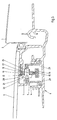
- Fig. 4 is a larger scale sectional view along line IV-IV in Fig. 1, wherein the closure element is shown in a half-open ventilating position, however.
- Fig. 5 is a view corresponding to Fig. 4, wherein the closure element is shown to have been moved downwards.
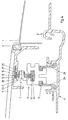
- Fig. 6 is a sectional view along line VI-VI in Fig. 1.
-
- The drawings show a
fixed roof 1 of a vehicle, such as a passenger car, which is provided with a roof opening 2 for receiving an open roof construction. The open roof construction includes aclosure element 3 for selectively closing or at least partially opening theroof opening 2. In this embodiment theclosure element 3 is a rigid panel, in particular a transparent panel of glass or plastic, but also other closure elements such as louvres or a flexible liner are conceivable. In the illustrated embodiment a sliding-tilt roof is used, whereinpanel 3 can be moved from the closed position in roof opening 2 (Fig. 6), on the one hand to an upwardly sloping ventilating position (Fig. 1) and on the other hand downwards (Fig. 5) and subsequently rearwards to a position under the fixed roof 1 (Fig. 4). - In order to enable the movements of
panel 3,panel 3 is fitted with anoperating mechanism 4 at both edges extending in the longitudinal direction of the open roof construction, which operating mechanisms each include alink slide 5 in this embodiment, which is slidably accommodated in a guideway of aguide rail 6. Saidguide rail 6 is mounted on or forms part of a stationary part (not shown), for example a frame, which is attached to the fixed roof of the vehicle. Theguide rails 6 extend along the longitudinally extending edges of the roof opening 2 and possibly rearwards thereof. - Part of the
operating mechanism 4 is made up of alink 7, which is attached to the underside ofpanel 3, near the respective longitudinal edge, and in particular to astiffening frame 8 thereof. To this end thestiffening frame 8 includes downwardly projectinglips 9, two for each longitudinal edge ofpanel 3 in this embodiment. The connection betweenlips 9 andlink 5 forms part of the subject matter of the present invention and will be discussed in more detail hereafter. -
Link 7 includes twosliding shoes 11 at its front end, which are slidably accommodated in associated grooves ofguide rail 6. - As Figs. 2 - 6 show,
link 7 is made up of twolink plates link plates panel 3. The rear part oflink plates flange 15 at the lower edge thereof. Saidflanges 15 are enveloped in plastic which has been formed thereon by injection molding, so as to form aguideway 16 having the desired curvature. Saidguideway 16 forms part of theoperating mechanism 4 for effecting the desired movements ofpanel 3. Since theoperating mechanism 4 is hardly relevant, if at all, to the present invention, the various parts and the operation thereof will not be explained in more detail herein. The figures do show, however, that the twoguideways 16 are interconnected at the rear end oflink 7 by means of an integrated connectingmember 17, which also functions to hold the twolink plates - As is furthermore shown in Figs. 2 - 6, in order to enable a connection between
lips link 5, thelink plates slot lip slot link plate 12 is provided with apassage fixing screw link plate 13 is so formed at the location of receivingslot fixing screw link plates respective lip Lips hole 26, 27 which is slightly elongated in vertical direction, which makes it possible to adjustlink 7 slightly in vertical direction relative topanel 3. -
Link plates slots link plate 12 is formed with afurther indentation 28 surrounding throughhole 21 at the location of therear receiving slot 19, which functions to receive part of the head of thefixing screw 23. - As is shown in Fig. 5, as a result of this shape of the
link plates lip 10,fixing screw 23 is so positioned in transverse direction and the length of thefixing screw 23 can be so small that thefixing screw 23 can be accommodated betweenside walls 29 oflink slide 5 in a downward position ofpanel 3, thus making it possible to realise a very compact construction having a small overall height of the open roof construction. The figure furthermore shows thatlips operating mechanisms 4, seen in transverse direction, as a result of which the forces frompanel 3 are transmitted to the center of theoperating mechanisms 4, thus preventing the development of flexural forces in transverse direction, which might lead to a reduced strength, wear and noise from theoperating mechanism 4. - Fig. 6 furthermore shows that no indentation of
link plate 12 is required at thefront lip 9, since theguide rail 6 is wide enough at that location for receiving the link and thefixing screw 22. - From the foregoing it will be understood that the invention provides an open roof construction and a link therefor which is remarkable for its compactness, simplicity and stability.
- The invention is not restricted to the above-described embodiment as shown in the drawing, which can be varied in several ways without departing from the scope of the invention. Thus it is possible to form the link of a single plate member which has been folded double instead of using two separate plates. Furthermore it is possible to use a different fixing element, for example a pop rivet.
Claims (10)
- An open roof construction for a vehicle having an opening (2) in its fixed roof (1), comprising a closure element (3), in particular a panel, for selectively closing or at least partially opening the roof opening, and at least one operating mechanism (4) comprising a plate-shaped link (7), which is connected to said closure element at the location of at least one point of attachment via an at least substantially vertical lip (9, 10) on the underside of said closure element, wherein said link (7) and said lip (9, 10) are provided with a hole (20, 21, 24, 25, 26, 27) for allowing the passage of a fixing element (22, 23), characterized in that said link (7) includes two plate members (12, 13) at least at the location of the point of attachment, between which the lip (9, 10) of the closure element (3) is accommodated.
- An open roof construction according to claim 1, wherein the plate members (12, 13) form the link (7), which plate members (12, 13) are bent outwards at the location of the point of attachment so as to form a receiving slot (18, 19) for the lip (9, 10) of the closure element (3).
- An open roof construction according to claim 2, wherein at least one plate member (12, 13) comprises a reduced thickness at the location of said receiving slot (18, 19).
- An open roof construction according to claim 3, wherein the fixing element (22, 23) consists of a fixing screw, and the hole (24, 25) in one plate member (13) is internally threaded for receiving the fixing screw (22, 23) therein, whilst the hole (20, 21) in the other plate member (12) forms a passage for the fixing screw, and the part of the plate member (12) surrounding said passage (20, 21) is arranged for abutment of a screw head of the fixing screw (22, 23).
- An open roof construction according to claim 4, wherein the plate member (12) comprising the passage (21) for the fixing screw (23) is locally formed with an indentation surrounding the passage (21) for receiving the screw head.
- An open roof construction according to any one of the preceding claims, wherein said link (6) includes a guideway (16) for cooperation with a guide member of the operating mechanism (4), wherein the guideway is configured as a curved rib which projects from either side of the link (7).
- An open roof construction according to claim 6, wherein the guideway (16) is made up of outwardly bent flanges (15) on the lower side of the plate members (12, 13), which are preferably enveloped in a plastic which has been formed thereon by injection molding.
- An open roof construction according to any one of the preceding claims, wherein each operating mechanism (4) is accommodated in a guide rail (6) which extends in the longitudinal direction of the open roof construction, and the operating mechanism (4) includes a slide (5) which is capable of sliding movement in the guide rail (6), wherein the length of the fixing element (22, 23) and its position in the transverse direction of the open roof construction is such that in a lowermost position of the closure element (3) the fixing element (22, 23) is at least partially accommodated between walls of at least one of the slide (5) and the guide rail (6).
- An open roof construction according to claim 8 in the form of a sliding roof comprising a rigid panel (3) as the closure element, which can be moved downward from a closed position in the roof opening (2) and subsequently rearwards to a position under the fixed roof (1) of the vehicle.
- A closure element for use in an open roof construction according to any one of the preceding claims.
Priority Applications (1)
| Application Number | Priority Date | Filing Date | Title |
|---|---|---|---|
| DE20023526U DE20023526U1 (en) | 1999-04-22 | 2000-04-06 | Open roof construction for vehicle, has link including two plate members at least at the location of the point of attachment between which the lip of the closure element is accommodated |
Applications Claiming Priority (2)
| Application Number | Priority Date | Filing Date | Title |
|---|---|---|---|
| NL1011859A NL1011859C2 (en) | 1999-04-22 | 1999-04-22 | Open roof construction for a vehicle. |
| NL1011859 | 1999-04-22 |
Publications (3)
| Publication Number | Publication Date |
|---|---|
| EP1046528A1 true EP1046528A1 (en) | 2000-10-25 |
| EP1046528B1 EP1046528B1 (en) | 2004-10-13 |
| EP1046528B2 EP1046528B2 (en) | 2008-03-26 |
Family
ID=19769058
Family Applications (1)
| Application Number | Title | Priority Date | Filing Date |
|---|---|---|---|
| EP00201259A Expired - Lifetime EP1046528B2 (en) | 1999-04-22 | 2000-04-06 | Open roof construction for a vehicle |
Country Status (5)
| Country | Link |
|---|---|
| US (1) | US6494529B1 (en) |
| EP (1) | EP1046528B2 (en) |
| JP (1) | JP4570726B2 (en) |
| DE (1) | DE60014745T3 (en) |
| NL (1) | NL1011859C2 (en) |
Cited By (5)
| Publication number | Priority date | Publication date | Assignee | Title |
|---|---|---|---|---|
| EP1500539A1 (en) * | 2003-07-24 | 2005-01-26 | Webasto AG | Open roof for vehicle |
| WO2005058627A1 (en) * | 2003-12-19 | 2005-06-30 | Wilhelm Karmann Gmbh | Component of an adjusting mechanism for a convertible motor vehicle roof |
| DE102008017074B3 (en) * | 2008-04-03 | 2009-07-30 | Webasto Ag | Cover element support |
| CN102198788A (en) * | 2010-03-23 | 2011-09-28 | 银娜珐天窗系统集团股份有限公司 | Open roof construction for a vehicle |
| CN104442315A (en) * | 2013-09-19 | 2015-03-25 | 韦巴斯托股份公司 | Vehicle sunroof device |
Families Citing this family (13)
| Publication number | Priority date | Publication date | Assignee | Title |
|---|---|---|---|---|
| DE60229831D1 (en) * | 2002-01-25 | 2008-12-24 | Inalfa Roof Sys Group Bv | Vehicle with lift-and-slide roof |
| DE10213994A1 (en) * | 2002-03-27 | 2003-10-16 | Arvinmeritor Gmbh | Movable cover for vehicle roof and sliding / lifting roof module |
| EP1494883B1 (en) * | 2002-04-12 | 2007-08-08 | Inalfa Roof Systems Group B.V. | Roof assembly for a vehicle |
| US6695398B2 (en) * | 2002-06-13 | 2004-02-24 | Webasto Sunroofs, Inc. | Spoiler sunroof mechanism |
| DE102005032437A1 (en) * | 2005-07-09 | 2007-01-11 | Webasto Ag | Vehicle roof with a movable roof part |
| EP2305500B1 (en) * | 2009-10-05 | 2013-09-25 | Inalfa Roof Systems Group B.V. | Open roof construction for a vehicle |
| US9193246B2 (en) * | 2013-03-11 | 2015-11-24 | S.A.W. Group, Llc | Universal replacement ventilator lid assembly |
| JP6158654B2 (en) * | 2013-09-19 | 2017-07-05 | ベバスト ジャパン株式会社 | Sunroof lid support structure |
| EP2857169B1 (en) * | 2013-10-01 | 2017-12-13 | Inalfa Roof Systems Group B.V. | Constructional assembly and method for making it |
| EP3173271B1 (en) | 2015-11-26 | 2018-07-18 | Inalfa Roof Systems Group B.V. | An open roof construction for a vehicle |
| EP3405358B1 (en) * | 2016-01-18 | 2020-09-02 | Webasto SE | Arrangement and method for producing an arrangement for a vehicle roof and a system for a motor vehicle with a vehicle roof |
| US11440385B2 (en) | 2017-08-03 | 2022-09-13 | Inalfa Roof Systems Group B.V. | Open roof construction for a vehicle |
| CN111469954B (en) * | 2020-04-21 | 2025-11-07 | 西艾科德管理(上海)有限公司 | Assembling structure and assembling method for automobile sky window |
Citations (4)
| Publication number | Priority date | Publication date | Assignee | Title |
|---|---|---|---|---|
| DE9116412U1 (en) * | 1991-10-30 | 1992-12-24 | Locher, Gebhard, Sarnthein, Südtirol | Door handle arrangement |
| DE4405742C1 (en) * | 1994-02-23 | 1995-05-04 | Wahl Peter Gmbh & Co | Slotted guide link for sliding panels on tilt-and-slide roof constructions for motor vehicles |
| EP0747249A1 (en) * | 1995-06-10 | 1996-12-11 | WEBASTO KAROSSERIESYSTEME GmbH | Guiding rail for sliding and tilting sunroof panel |
| EP0899140A1 (en) | 1997-08-28 | 1999-03-03 | Inalfa Industries B.V. | Open roof contruction for a vehicle |
Family Cites Families (29)
| Publication number | Priority date | Publication date | Assignee | Title |
|---|---|---|---|---|
| FR2474971A1 (en) | 1980-01-31 | 1981-08-07 | Renault | DEVICE FOR MANEUVERING A SUNROOF OF A MOTOR VEHICLE |
| DE3020675C2 (en) | 1980-05-30 | 1987-01-02 | Rockwell Golde Gmbh, 6000 Frankfurt | Lift and slide roof for motor vehicles |
| NL8006480A (en) | 1980-11-28 | 1982-06-16 | Vermeulen Hollandia Octrooien | SLIDING ROOF FOR A VEHICLE. |
| DE3221487C2 (en) | 1982-06-07 | 1989-12-14 | Rockwell Golde Gmbh, 6000 Frankfurt | Cable routing for motor vehicle sunroofs |
| JPS6071327A (en) | 1983-09-29 | 1985-04-23 | Johnan Seisakusho Co Ltd | Opening and closing method for car sun roof and device thereof |
| EP0143589B1 (en) | 1983-11-25 | 1989-01-18 | Britax Weathershields Limited | Opening roof for a motor vehicle |
| DE3417098A1 (en) | 1984-05-09 | 1985-11-14 | Webasto-Werk W. Baier GmbH & Co, 8035 Gauting | VEHICLE SUNROOF |
| DE3444522A1 (en) | 1984-10-02 | 1986-04-10 | Webasto-Werk W. Baier GmbH & Co, 8035 Gauting | SLIDING LIFTING ROOF |
| DE3442600A1 (en) | 1984-11-22 | 1986-05-28 | Daimler-Benz Ag, 7000 Stuttgart | Sliding and tilt-up roof |
| DE3510759A1 (en) * | 1985-03-25 | 1986-09-25 | Karosseriewerke Weinsberg Gmbh, 7102 Weinsberg | Height-adjustment device for vehicle roof covers which can at least be knocked out |
| JPS61278422A (en) | 1985-06-04 | 1986-12-09 | Oi Seisakusho Co Ltd | Sunroofing device for vehicle |
| DE3529118C1 (en) | 1985-08-14 | 1990-01-25 | Adam Opel Ag, 6090 Ruesselsheim, De | |
| DE3532679C1 (en) | 1985-09-13 | 1986-11-27 | Adam Opel AG, 6090 Rüsselsheim | Guide bolts in a sunroof arrangement |
| DE3537964C1 (en) | 1985-10-25 | 1987-02-19 | Rockwell Golde Gmbh | Cable guide for motor vehicle sliding roofs |
| DE3603314A1 (en) | 1986-02-04 | 1987-08-06 | Weinsberg Karosseriewerke | Tilt-and-slide sunroof for vehicles |
| NL8701492A (en) | 1987-06-25 | 1989-01-16 | Vermeulen Hollandia Octrooien | OPEN ROOF CONSTRUCTION FOR A VEHICLE. |
| DE3910894C3 (en) | 1988-04-05 | 2000-12-14 | Aisin Seiki | Movement mechanism for a lid of a vehicle roof cutout |
| NL8801359A (en) | 1988-05-27 | 1988-08-01 | Vermeulen Hollandia Octrooien | OPEN ROOF CONSTRUCTION FOR A VEHICLE. |
| NL8803010A (en) | 1988-12-08 | 1990-07-02 | Vermeulen Hollandia Octrooien | SLIDING ROOF FOR A VEHICLE. |
| JP2520859Y2 (en) * | 1989-02-27 | 1996-12-18 | 日産自動車株式会社 | Car sunroof structure |
| DE3908645C1 (en) * | 1989-03-16 | 1990-06-13 | Rockwell Golde Gmbh, 6000 Frankfurt, De | |
| DE3930756A1 (en) | 1989-09-14 | 1991-03-28 | Webasto Ag Fahrzeugtechnik | Sliding and tilting sunroof operating mechanism - has two levers, fixed at one end to each other and extending in same direction |
| NL9100972A (en) | 1991-06-06 | 1993-01-04 | Vermeulen Hollandia Octrooien | LIFT-SLIDING ROOF FOR A VEHICLE. |
| JP3269189B2 (en) | 1993-07-13 | 2002-03-25 | アイシン精機株式会社 | Sunroof device for vehicles |
| DE4415235C1 (en) * | 1994-04-30 | 1995-09-28 | Paul Zitzmann Gmbh & Co Kg Dru | Slide for a vehicle roof section |
| DE19514585C5 (en) | 1995-04-20 | 2004-11-18 | Gubesch Gmbh | Sliding element for a link part of a sliding / lifting roof of a motor vehicle |
| JP3505307B2 (en) | 1996-01-08 | 2004-03-08 | ベバスト ジャパン株式会社 | Slide tilt roof device |
| JP3755924B2 (en) * | 1996-03-25 | 2006-03-15 | ベバスト ジャパン株式会社 | Sunroof device |
| DE19647733C2 (en) * | 1996-11-19 | 1999-02-25 | Webasto Karosseriesysteme | Actuating mechanism for vehicle roof |
-
1999
- 1999-04-22 NL NL1011859A patent/NL1011859C2/en not_active IP Right Cessation
-
2000
- 2000-04-06 EP EP00201259A patent/EP1046528B2/en not_active Expired - Lifetime
- 2000-04-06 DE DE60014745T patent/DE60014745T3/en not_active Expired - Lifetime
- 2000-04-12 JP JP2000111195A patent/JP4570726B2/en not_active Expired - Lifetime
- 2000-04-21 US US09/556,110 patent/US6494529B1/en not_active Expired - Lifetime
Patent Citations (4)
| Publication number | Priority date | Publication date | Assignee | Title |
|---|---|---|---|---|
| DE9116412U1 (en) * | 1991-10-30 | 1992-12-24 | Locher, Gebhard, Sarnthein, Südtirol | Door handle arrangement |
| DE4405742C1 (en) * | 1994-02-23 | 1995-05-04 | Wahl Peter Gmbh & Co | Slotted guide link for sliding panels on tilt-and-slide roof constructions for motor vehicles |
| EP0747249A1 (en) * | 1995-06-10 | 1996-12-11 | WEBASTO KAROSSERIESYSTEME GmbH | Guiding rail for sliding and tilting sunroof panel |
| EP0899140A1 (en) | 1997-08-28 | 1999-03-03 | Inalfa Industries B.V. | Open roof contruction for a vehicle |
Cited By (9)
| Publication number | Priority date | Publication date | Assignee | Title |
|---|---|---|---|---|
| EP1500539A1 (en) * | 2003-07-24 | 2005-01-26 | Webasto AG | Open roof for vehicle |
| WO2005058627A1 (en) * | 2003-12-19 | 2005-06-30 | Wilhelm Karmann Gmbh | Component of an adjusting mechanism for a convertible motor vehicle roof |
| US7575268B2 (en) | 2003-12-19 | 2009-08-18 | Wilhelm Karmann Gmbh | Component of an adjusting mechanism for a convertible motor vehicle roof |
| DE102008017074B3 (en) * | 2008-04-03 | 2009-07-30 | Webasto Ag | Cover element support |
| CN102198788A (en) * | 2010-03-23 | 2011-09-28 | 银娜珐天窗系统集团股份有限公司 | Open roof construction for a vehicle |
| CN102198788B (en) * | 2010-03-23 | 2015-04-08 | 银娜珐天窗系统集团股份有限公司 | Open roof construction for a vehicle |
| CN104442315A (en) * | 2013-09-19 | 2015-03-25 | 韦巴斯托股份公司 | Vehicle sunroof device |
| WO2015040018A1 (en) * | 2013-09-19 | 2015-03-26 | Webasto SE | Vehicle sunroof device |
| US9592723B2 (en) | 2013-09-19 | 2017-03-14 | Webasto SE | Vehicle sunroof device |
Also Published As
| Publication number | Publication date |
|---|---|
| JP2000313235A (en) | 2000-11-14 |
| EP1046528B2 (en) | 2008-03-26 |
| NL1011859C2 (en) | 2000-10-24 |
| DE60014745T3 (en) | 2008-08-28 |
| JP4570726B2 (en) | 2010-10-27 |
| EP1046528B1 (en) | 2004-10-13 |
| DE60014745D1 (en) | 2004-11-18 |
| US6494529B1 (en) | 2002-12-17 |
| DE60014745T2 (en) | 2005-10-20 |
Similar Documents
| Publication | Publication Date | Title |
|---|---|---|
| EP1046528B1 (en) | Open roof construction for a vehicle | |
| CN100393541C (en) | car sunroof system | |
| EP1070614B1 (en) | Open roof construction for a vehicle | |
| US7178862B2 (en) | Sliding roof system | |
| US6471286B1 (en) | Open roof construction for a vehicle | |
| EP1070616B1 (en) | Open roof construction for a vehicle | |
| US7255392B2 (en) | Guide rail system for a moveable sunroof system including a sunshade and method of producing a guide rail system for a moveable sunroof system | |
| EP2305500B1 (en) | Open roof construction for a vehicle | |
| EP1084881A1 (en) | Open roof construction for a vehicle | |
| EP0520523A1 (en) | Open roof construction for a vehicle | |
| EP1488945B1 (en) | Open roof construction for a vehicle | |
| EP1073564B1 (en) | Open roof construction for a vehicle | |
| US20020021030A1 (en) | Open roof construction for a vehicle | |
| EP1167098A1 (en) | Open roof construction for a vehicle | |
| EP0328338B1 (en) | Vehicle sunroof | |
| EP4197837B1 (en) | Roof system and method of operating it | |
| NL1011184C2 (en) | Sun roof for motor vehicle, has cross direction reinforcing structure for improving side impact resistance releasably secured to length beams in sun roof frame | |
| US6659542B2 (en) | Vehicle roof with sliding roof element | |
| JP2543213Y2 (en) | Sunroof slide mechanism | |
| US20170368920A1 (en) | Side shield arrangement and openable roof system of an automotive vehicle |
Legal Events
| Date | Code | Title | Description |
|---|---|---|---|
| PUAI | Public reference made under article 153(3) epc to a published international application that has entered the european phase |
Free format text: ORIGINAL CODE: 0009012 |
|
| AK | Designated contracting states |
Kind code of ref document: A1 Designated state(s): DE FR GB |
|
| AX | Request for extension of the european patent |
Free format text: AL;LT;LV;MK;RO;SI |
|
| AKX | Designation fees paid |
Free format text: DE FR GB |
|
| 17P | Request for examination filed |
Effective date: 20010315 |
|
| 17Q | First examination report despatched |
Effective date: 20030414 |
|
| RAP1 | Party data changed (applicant data changed or rights of an application transferred) |
Owner name: INALFA ROOF SYSTEMS GROUP B.V. |
|
| GRAP | Despatch of communication of intention to grant a patent |
Free format text: ORIGINAL CODE: EPIDOSNIGR1 |
|
| GRAS | Grant fee paid |
Free format text: ORIGINAL CODE: EPIDOSNIGR3 |
|
| GRAA | (expected) grant |
Free format text: ORIGINAL CODE: 0009210 |
|
| AK | Designated contracting states |
Kind code of ref document: B1 Designated state(s): DE FR GB |
|
| REG | Reference to a national code |
Ref country code: GB Ref legal event code: FG4D |
|
| REF | Corresponds to: |
Ref document number: 60014745 Country of ref document: DE Date of ref document: 20041118 Kind code of ref document: P |
|
| PLBI | Opposition filed |
Free format text: ORIGINAL CODE: 0009260 |
|
| PLAX | Notice of opposition and request to file observation + time limit sent |
Free format text: ORIGINAL CODE: EPIDOSNOBS2 |
|
| 26 | Opposition filed |
Opponent name: WEBASTO AG Effective date: 20050713 |
|
| ET | Fr: translation filed | ||
| PLAF | Information modified related to communication of a notice of opposition and request to file observations + time limit |
Free format text: ORIGINAL CODE: EPIDOSCOBS2 |
|
| PLBB | Reply of patent proprietor to notice(s) of opposition received |
Free format text: ORIGINAL CODE: EPIDOSNOBS3 |
|
| APBP | Date of receipt of notice of appeal recorded |
Free format text: ORIGINAL CODE: EPIDOSNNOA2O |
|
| APAH | Appeal reference modified |
Free format text: ORIGINAL CODE: EPIDOSCREFNO |
|
| APBP | Date of receipt of notice of appeal recorded |
Free format text: ORIGINAL CODE: EPIDOSNNOA2O |
|
| APBU | Appeal procedure closed |
Free format text: ORIGINAL CODE: EPIDOSNNOA9O |
|
| PUAH | Patent maintained in amended form |
Free format text: ORIGINAL CODE: 0009272 |
|
| STAA | Information on the status of an ep patent application or granted ep patent |
Free format text: STATUS: PATENT MAINTAINED AS AMENDED |
|
| 27A | Patent maintained in amended form |
Effective date: 20080326 |
|
| AK | Designated contracting states |
Kind code of ref document: B2 Designated state(s): DE FR GB |
|
| PGFP | Annual fee paid to national office [announced via postgrant information from national office to epo] |
Ref country code: GB Payment date: 20080424 Year of fee payment: 9 |
|
| ET3 | Fr: translation filed ** decision concerning opposition | ||
| GBPC | Gb: european patent ceased through non-payment of renewal fee |
Effective date: 20090406 |
|
| PG25 | Lapsed in a contracting state [announced via postgrant information from national office to epo] |
Ref country code: GB Free format text: LAPSE BECAUSE OF NON-PAYMENT OF DUE FEES Effective date: 20090406 |
|
| REG | Reference to a national code |
Ref country code: FR Ref legal event code: PLFP Year of fee payment: 16 |
|
| REG | Reference to a national code |
Ref country code: FR Ref legal event code: PLFP Year of fee payment: 17 |
|
| REG | Reference to a national code |
Ref country code: FR Ref legal event code: PLFP Year of fee payment: 18 |
|
| REG | Reference to a national code |
Ref country code: FR Ref legal event code: PLFP Year of fee payment: 19 |
|
| PGFP | Annual fee paid to national office [announced via postgrant information from national office to epo] |
Ref country code: DE Payment date: 20190429 Year of fee payment: 20 |
|
| PGFP | Annual fee paid to national office [announced via postgrant information from national office to epo] |
Ref country code: FR Payment date: 20190425 Year of fee payment: 20 |
|
| REG | Reference to a national code |
Ref country code: DE Ref legal event code: R071 Ref document number: 60014745 Country of ref document: DE |