EP1045802B1 - Bag - Google Patents
Bag Download PDFInfo
- Publication number
- EP1045802B1 EP1045802B1 EP99900545A EP99900545A EP1045802B1 EP 1045802 B1 EP1045802 B1 EP 1045802B1 EP 99900545 A EP99900545 A EP 99900545A EP 99900545 A EP99900545 A EP 99900545A EP 1045802 B1 EP1045802 B1 EP 1045802B1
- Authority
- EP
- European Patent Office
- Prior art keywords
- bag
- tubular members
- tubular
- tubular member
- adjacent
- Prior art date
- Legal status (The legal status is an assumption and is not a legal conclusion. Google has not performed a legal analysis and makes no representation as to the accuracy of the status listed.)
- Expired - Lifetime
Links
Images
Classifications
-
- B—PERFORMING OPERATIONS; TRANSPORTING
- B66—HOISTING; LIFTING; HAULING
- B66C—CRANES; LOAD-ENGAGING ELEMENTS OR DEVICES FOR CRANES, CAPSTANS, WINCHES, OR TACKLES
- B66C1/00—Load-engaging elements or devices attached to lifting or lowering gear of cranes or adapted for connection therewith for transmitting lifting forces to articles or groups of articles
- B66C1/10—Load-engaging elements or devices attached to lifting or lowering gear of cranes or adapted for connection therewith for transmitting lifting forces to articles or groups of articles by mechanical means
- B66C1/22—Rigid members, e.g. L-shaped members, with parts engaging the under surface of the loads; Crane hooks
- B66C1/226—Rigid members, e.g. L-shaped members, with parts engaging the under surface of the loads; Crane hooks for flexible intermediate bulk containers [FIBC]
-
- B—PERFORMING OPERATIONS; TRANSPORTING
- B65—CONVEYING; PACKING; STORING; HANDLING THIN OR FILAMENTARY MATERIAL
- B65D—CONTAINERS FOR STORAGE OR TRANSPORT OF ARTICLES OR MATERIALS, e.g. BAGS, BARRELS, BOTTLES, BOXES, CANS, CARTONS, CRATES, DRUMS, JARS, TANKS, HOPPERS, FORWARDING CONTAINERS; ACCESSORIES, CLOSURES, OR FITTINGS THEREFOR; PACKAGING ELEMENTS; PACKAGES
- B65D88/00—Large containers
- B65D88/16—Large containers flexible
- B65D88/1612—Flexible intermediate bulk containers [FIBC]
- B65D88/1675—Lifting fittings
- B65D88/1681—Flexible, e.g. loops, or reinforcements therefor
- B65D88/1687—Flexible, e.g. loops, or reinforcements therefor specially adapted for the forks of a forklift
Definitions
- the present invention relates to a bag for bulk storage and transport of materials according to the preambles of claims 1 to 10, notably particulate solids materials as well as to a device for securing to a collapsible bag according to the preamble of claim 11.
- the invention also provides a method of manufacturing a bag.
- Bags for storage and transport of bulk materials are typically of generally cuboid shape, formed from a fabric material such as polypropylene.
- the weight of fabric material will be from about 180 g/m 2 to 400 g/m 2 depending on the intended load and operating conditions.
- the fabric may be reinforced for extra strength.
- the bags have a top which is either permanently fully open or which can be opened, for loading.
- the bottoms of the bags are typically provided with a discharge spout through which the contents of the bag can be emptied when the spout is opened.
- the base of the bag may be openable for discharge of the contents.
- each bag is typically provided with a lifting loop at each corner.
- a fork-lift operator brings the tines of the fork close to the top of one edge of the filled bag so that each tine is adjacent to a lifting loop.
- An assistant lifts up each lifting loop to enable a tine to pass through the loop while the operator moves the tines forward over the bag.
- the fork-lift operator moves the tines further over the top of the bag until the tines are adjacent the rear pair of lifting loops, and the process is repeated so that the tines are disposed through the rear lifting loops.
- the bag can then be lifted and moved.
- a problem with this procedure is that there is a danger of injury to the assistant when the tines or the fork are moved. This is a particular problem when filled bags are stacked high, on top of each other. The fork-lift operator is unable to see the rear pair of lifting loops when the stack is too high, and the assistant may be injured by a tine or pushed off a ladder. It is also costly to employ two men to secure the bag on the fork.
- the fork-lift operator must move the truck so that the tines of the fork are positioned near the front loops. He must then get out of the cab of the truck, hook the front loops over the tines, and get back in the cab. He must then drive the truck forward as far as he thinks necessary, get out again, hook the rear loops onto the tines (if he has judged the forward distance correctly), get back in the cab, drive further forward to pick up the bag. The procedure is slow and can be dangerous.
- a collapsible bag for the storage and transport of bulk materials, as specified in Claim 1
- Another aspect of the invention provides a collapsible bag for the storage and transport of bulk materials as specified in Claim 10.
- Resilient tubular members function as guides for the tines of a fork-lift so that, once the tines have been inserted into one end of the tubular member, full insertion of the tines through the tubular members can be accomplished without an assistant and without the need for a fork-lift truck operator to leave the truck.
- tubular members are resilient, they lie flat when under load, for example when other filled bags are stacked on top, but revert to a predetermined sectional shape when the load is removed. This allows stacking of bags without significant wasted space, and permits lifting and moving of the bags by a fork-lift operator without an assistant.
- Rigid connection of tubular members ensures that they are spaced apart from each other by a predetermined distance so that the tines of a fork, suitably spaced apart, can be inserted into the tubular members without undue difficulty.
- the term "rigid" is used herein to denote a linkage which is sufficiently stiff to maintain the necessary separation between the tubular members. The skilled person will therefore appreciate that the spacers therefore need not be totally unyielding, particularly where the tubular members are dimensioned to allow some tolerance for receiving the tines of a fork-lift.
- the spacers may be made from any suitable structural material. Suitable materials include metals or structural plastics materials, for example nylon or an injection-moulded plastics material.
- the tubular members may carry load along their length when the filled bag is suspended, or strong points in the tubular members may take the load of a filled bag, so that other regions of the tubular members need not be substantially load carrying.
- the tubular members may be secured in relation to the top edges of at least some of the side panels by direct attachment to the edges, for example by sewing, gluing or riveting, or they may be formed integrally with the edges as will be further described below.
- tubular members may be secured in relation to the edges by means of lifting loops on a conventional bag.
- the bag is formed from a conventional bag with a lifting loop at each corner, by fitting an insert to the bag and securing it by means of the lifting loops.
- the insert comprises a pair of substantially parallel resilient tubular members which are connected together at or adjacent to each end by rigid spacing means.
- the tubular members have laterally extending slots or apertures on their upper surfaces for receiving the lifting loops, and the tubular members are of sufficient size that at least the top portion of each loop is disposed inside a tubular member when the insert is fitted on the bag.
- the tubular members thus function as guides for the tines of a fork-lift, but the lifting loops take the load when the bag is lifted on the tines.
- another aspect of the present invention comprises a device for securing to a bag for the storage and transport of bulk materials, as specified in Claim 11.
- the tubular members may be made from any suitable resilient material, for example a natural or synthetic rubber material.
- a preferred material is vulcanised rubber, or the sort of rubber that wellington boots are typically made from.
- the inside surfaces of the tubular members may optionally be provided with a tough coating to confer resistance to cutting and scratching by the tines of a fork-lift.
- tubular members may be of any cross sectional shape which will accept the tines of a fork-lift or the like.
- the tubular members may be circular, rectangular, square or oval in cross section.
- the invention will be described with reference to tubular members which are substantially circular in section. However, it is to be understood that the invention is not limited to this embodiment.
- the tubular members may be of any suitable diameter to receive a tine of a fork-lift, for example they may have a diameter in the range 100 to 300 mm, notably about 200 mm.
- the bags can be made by other methods.
- the tubular members may be manufactured separately and subsequently secured to opposite top edges of the box by securing means, for example stitching.
- the rigid connecting means may be secured to the tubular members either before or after the tubular members are secured to the edges of the box.
- the tubular members are formed from the material of the bag so that the tubular members are integral parts of the bag. This may be achieved, for example, by forming the bag with a pair of opposed sides which are longer than the other pair of opposed sides, and forming the extra length into tubes.
- a preferred material is polypropylene fabric.
- the tubular members may be reinforced by incorporation of a rubber material, to impart resilience. The rubber material may be secured to the tubular members by any suitable securing means, for example stitching or gluing.
- a further aspect of the invention provides a method of manufacturing a collapsible bag for the storage and transport of bulk materials as specified in Claim 13.
- Resilience may also be imparted by reinforcing the tubular member with a suitable reinforcing member, for example a wire of metal or plastics material which is helically wound around the tubular member.
- a suitable reinforcing member for example a wire of metal or plastics material which is helically wound around the tubular member.
- tubular members may be placed on a former to define a preferred shape and/or configuration, and sprayed with a fluid material that dries to a form-retaining coating to retain them in that preferred shape and/or configuration.
- the fluid material may be a foam or a lacquer.
- the collapsible bag 2 is formed from a structural fabric, in this example, polypropylene fabric of weight 300 g/m 2 .
- the weight of fabric used will, of course, depend on the maximum load which is to be carried by the bag 2.
- Methods of assembling suitable fabrics into a bag capable of carrying a load of particulate solids materials 8 are well known to those skilled in the art.
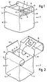
- the bag 2 is of a cuboid shape with a generally square plan section bottom panel 13.
- the bottom panel 13 will have a discharge spout (not shown) for emptying the contents.
- the bag 2 has pairs of opposed side walls 11, 12.
- Opposed walls 12 of the bag 2 have top edges 14, each of which is provided with a tubular member 4 secured to the edge 14 and extending along a substantial length thereof.
- a tubular member 4 is disposed along the entire length of each top edge 14.
- Each tubular member 4 is provided with a pair of straps 10 which are secured to the inner surface of the opposed walls 12 by securing means, in this example, stitching.
- the tubular members 4 are connected together by a pair of substantially rigid spacers 22 which serve to maintain the tubular members 4 in a configuration wherein their longitudinal central axes are substantially parallel.
- a fork-lift is inserted into an end opening 6 of each tubular member 4 so that the longitudinal axis of the tine is substantially parallel to or collinear with the longitudinal central axis of the tubular member 4, the tine may be pushed forwards through the tubular member 4 to its fullest extent.
- the tubular members 4 are resilient, so that they adopt a substantially circular cross sectional configuration in the absence of an applied load. This ensures that each tubular member 4 is open to receive a tine of a fork-lift when the bag 2 is on top of a pile.
- a fork-lift operator can insert the tines of his fork-lift into the tubular members 4, lift, move, and lower the filled bag 2, and remove the tines of the fork from the tubular members 4, without leaving his cab and without external assistance.
- FIG. 2 shows one step in a method of manufacturing the bag 2.
- the bag is fabricated by well known methods, but leaving one pair of opposed walls 12 with an additional length of fabric in the form of a flap 18.
- Each flap 18 is secured along a line defining an edge 14 by securing means, in this example by stitching, as shown by the arrows.
- the straps 10 are sewn to the insides of the respective opposed walls 12 for reinforcement.
- a rubber sheet 16 is secured to each tubular member 4, formed from the flap 18, by suitable securing means, for example gluing or stitching.
- the rubber reinforcement 16 imparts resilience to the tubular member 4.
- tubular members 4 are connected together at each end by a pair of substantially rigid spacer rods 22, in this example made of nylon, which are secured to the tubular members 4 by any suitable fixing means, for example by means of glue.
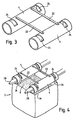
- a device for modifying a conventional bag with a lifting loop at each corner comprises a pair of substantially parallel resilient tubular members 4 connected together by a pair of rigid spacing rods 22 adjacent each end.
- the rods need to be spaced sufficiently far apart to permit filling of a bag through an area between them when the device is mounted on a bag.
- Each tubular member 4 is provided with a lateral slot or cut-out portion 24, through which a lifting loop of a bag will be disposed.
- the slot 24 is here shown having a long axis normal to the long axis of the tubular member 4. It will be understood that the slots may be other shapes and orientations providing that sufficient lateral access is presented for a lifting loop to be retained in the slot when appropriately presented.
- Figure 4 shows the device of Figure 3 in use, mounted on a conventional bag 2 with a strap or lifting loop 26 at each top corner.
- Each lifting loop 26 is disposed around a tubular member 4 and locates in a cut-out portion 24.
- the tines 28 of a fork-lift can readily enter the tubular members 4 and the weight of the bag is supported entirely by the lifting loops 26.
- the tubular members 4 act as guides for the tines 28 but do not support load.
- the ends of the tubular members 4 project beyond the edges of the bag 2, so that if a plurality of bags are stacked on top of each other, the middle regions of the resilient tubular members 4 are squashed by the resulting load, but the ends remain open.
- the end portions of the tubular members 4 therefore always retain the preferred sectional shape regardless of whether the middle of the tubular members 4 are squashed, and this helps the tubular members 4 to return quickly to their tubular shape when a load is removed.
- the invention provides a bag which can be moved and lifted by a single fork-lift truck operator without external help. Filled bags can be moved more safely than conventional bags, and with less manpower.
Landscapes
- Engineering & Computer Science (AREA)
- Mechanical Engineering (AREA)
- Bag Frames (AREA)
- Revetment (AREA)
- Information Retrieval, Db Structures And Fs Structures Therefor (AREA)
- Pallets (AREA)
- Making Paper Articles (AREA)
- External Artificial Organs (AREA)
- Supplying Of Containers To The Packaging Station (AREA)
- Packages (AREA)
- Valve Device For Special Equipments (AREA)
Abstract
Description
Claims (16)
- A collapsible bag (2) for the storage and transport of bulk materials, comprising a bottom panel (13), a plurality of side panels (11, 12), and a pair of substantially parallel tubular guide members (4) secured on or adjacent to the tops of at least some of the side panels (11, 12) and connected together by rigid spacing means (22) at or adjacent to their ends, characterised in that the tubular members (4) are resilient so that they lie flat when under load but revert to a predetermined sectional shape when the load is removed.
- A bag (2) as claimed in Claim 1, wherein the tubular members (4) are secured to at least one of the side panels by means of straps (26).
- A bag (2) as claimed in Claim 2, wherein the upper surface of each tubular member (4) is provided with a slot or cut-out portion (24) adjacent each end, a strap (26) being received in each slot (24) and at least the top portion of each of the said straps (26) being disposed inside a tubular member (4), so that when the tines of a fork-lift truck are inserted into the tubular members (4) under the top portions of the straps (26) and lifted, the weight of the bag (2) will be carried by the straps (26).
- A bag (2) as claimed in any one of the preceding claims, wherein each tubular member (4) is disposed along substantially the entire length of the top edge (14) of a side panel (12).
- A bag (2) as claimed in Claim 4, wherein the tubular members (4) extend longitudinally beyond the edges (14) of the side panels (12) along which they are disposed.
- A bag (2) as claimed in any one of the preceding claims, wherein the tubular members (4) are reinforced with a rubber material (16).
- A bag (2) as claimed in any one of the preceding claims, wherein the tubular members (4) are reinforced with a wire of metal or a plastics material which is helically wound around each tubular member.
- A bag (2) as claimed in any one of the preceding claims, which is of generally square or rectangular plan section.
- A bag (2) as claimed in any one of the preceding claims, wherein the bag (2) may be lifted by means of the tubular members (4).
- A collapsible bag (2) for the storage and transport of bulk materials, the bag having a generally square or rectangular plan section and being provided with a pair of tubular members (4) each secured to and disposed along a substantial length of an opposite top edge (14) thereof and connected together by rigid spacing (22) means at or adjacent to their ends, whereby the bag (2) may be lifted by means of the tubular members (4), characterised in that the tubular members (4) are resilient so that they lie flat when under load but revert to a predetermined sectional shape when the load is removed.
- A device for securing to a collapsible bag for the storage and transport of bulk materials comprising a bottom panel (13), a plurality of side panels (11, 12), and a plurality of straps or lifting loops (26) for lifting the bag, the device comprising a pair of substantially parallel tubular guide members (4) which are connected together at or adjacent to each end by rigid spacing means (22), characterised in that the tubular members (4) being resilient so that they lie flat when under load but revert to a predetermined sectional shape when the load is removed.
- A device as claimed in Claim 11, wherein each tubular member (4) has a slot or cut-out portion (24) adjacent each end for receiving a portion of a strap or lifting loop of a bag.
- A method of manufacturing a bag for the storage and transport of bulk materials, the bag having a bottom panel (13) and a plurality of side panels (11, 12) and being provided with a pair of substantially parallel tubular members (4) each secured to and disposed along the top edges (14) of a pair of opposed side panels (12); the method comprising forming the bag with one pair of opposed sides (12) which are longer than the other sides (11), securing the free end of each extra-length side (12) to that side so as to form a tubular member (4), providing each tubular member (4) with a resilient reinforcement (16) and connecting the tubular members (4) together at or adjacent each end by substantially rigid connecting means (22).
- A method as claimed in Claim 13, wherein the resilient reinforcement comprises a rubber reinforcing member (16).
- A method as claimed in Claim 13, wherein the resilient reinforcement is provided by placing each tubular member (4) on a former to define a preferred shape and/or configuration and spraying the tubular member (4) with a fluid material that dries to a form-retaining coating to retain it in that preferred shape and/or configuration.
- A method as claimed in claim 15, wherein the fluid material is a foam or lacquer.
Applications Claiming Priority (3)
| Application Number | Priority Date | Filing Date | Title |
|---|---|---|---|
| GB9800149A GB2333091A (en) | 1998-01-07 | 1998-01-07 | Bulk bag with tubular lifting members |
| GB9800149 | 1998-01-07 | ||
| PCT/GB1999/000037 WO1999035058A1 (en) | 1998-01-07 | 1999-01-06 | A bag |
Publications (2)
| Publication Number | Publication Date |
|---|---|
| EP1045802A1 EP1045802A1 (en) | 2000-10-25 |
| EP1045802B1 true EP1045802B1 (en) | 2002-10-16 |
Family
ID=10824843
Family Applications (1)
| Application Number | Title | Priority Date | Filing Date |
|---|---|---|---|
| EP99900545A Expired - Lifetime EP1045802B1 (en) | 1998-01-07 | 1999-01-06 | Bag |
Country Status (12)
| Country | Link |
|---|---|
| US (1) | US6390675B1 (en) |
| EP (1) | EP1045802B1 (en) |
| JP (1) | JP2002500142A (en) |
| AT (1) | ATE226176T1 (en) |
| AU (1) | AU737364B2 (en) |
| CA (1) | CA2317436C (en) |
| DE (1) | DE69903512T2 (en) |
| DK (1) | DK1045802T3 (en) |
| ES (1) | ES2186318T3 (en) |
| GB (1) | GB2333091A (en) |
| PT (1) | PT1045802E (en) |
| WO (1) | WO1999035058A1 (en) |
Families Citing this family (16)
| Publication number | Priority date | Publication date | Assignee | Title |
|---|---|---|---|---|
| US6926144B1 (en) | 2002-08-27 | 2005-08-09 | Daniel R. Schnaars, Jr. | Bulk bag pallet tube apparatus |
| CA2409471C (en) * | 2002-10-23 | 2010-10-12 | Lsi - Lift Systems Incorporated | Bulk bag and rigid fork lift tine receiving member combination |
| GB0225235D0 (en) * | 2002-10-30 | 2002-12-11 | Looplifter Ltd | Support Device |
| US7226209B2 (en) | 2002-10-30 | 2007-06-05 | Looplifter Limited | Bulk bags |
| US6935500B1 (en) | 2002-12-05 | 2005-08-30 | Daniel R. Schnaars | Bulk bag with support system |
| US7591370B1 (en) | 2004-10-18 | 2009-09-22 | Schnaars Daniel R | Pot belly bag with a pair of sleeves |
| US20060222270A1 (en) * | 2005-04-04 | 2006-10-05 | Modena Henry P | Flowable material container |
| US7757851B2 (en) * | 2005-11-15 | 2010-07-20 | Schnaars Daniel R | Pot belly bag |
| AU2008204448B2 (en) | 2007-01-11 | 2014-02-27 | Cyxer Limited | Device and method for handling containers and container comprising said device |
| US8322924B2 (en) * | 2008-11-06 | 2012-12-04 | Robert Noble | Trash collection and removal system |
| US9604779B2 (en) * | 2015-04-28 | 2017-03-28 | Peter J. Ristagno | Portable trash container |
| US20170022016A1 (en) * | 2015-07-24 | 2017-01-26 | Potters Industries, Llc | Bulk Bag Design With Pass-Through Forklift Tine Sleeves and Method of Use |
| USD893181S1 (en) * | 2017-04-07 | 2020-08-18 | Codefine S.A. | Bulk bag |
| KR101935720B1 (en) * | 2018-04-27 | 2019-01-04 | 이종수 | Carriage bag and manufacturing method thereof |
| CN211168223U (en) * | 2019-08-29 | 2020-08-04 | 湘潭皓康生态材料有限公司 | Special flexible container of improvement container of convenient loading and unloading |
| DE102020124321B4 (en) | 2020-09-17 | 2022-07-28 | Friedrich Zufall GmbH & Co. KG Internationale Spedition | FIBC forklift fork |
Family Cites Families (23)
| Publication number | Priority date | Publication date | Assignee | Title |
|---|---|---|---|---|
| US1512053A (en) * | 1923-05-29 | 1924-10-21 | Ridlinghafer Charles | Market-bag carrier |
| US3282621A (en) * | 1963-12-26 | 1966-11-01 | Thomas G Peterson | Combination lifting pallet and collapsible storage and shipping container |
| FR1443272A (en) * | 1965-05-10 | 1966-06-24 | Saint Freres | Flexible parallelepipedal container |
| GB1459448A (en) | 1973-02-27 | 1976-12-22 | Nat Res Dev | Inhibition circuits for anemometers |
| FR2229574B1 (en) * | 1973-05-17 | 1977-01-07 | Burel Sa Ets F | |
| FR2306134A1 (en) * | 1975-04-02 | 1976-10-29 | Pedelucq Jean Michel | Container for bulk material - has carrying handle on base and lid and end closure formed of flaps |
| DE7607644U1 (en) * | 1976-03-12 | 1976-07-22 | Krause Walter | Transport container made of pliable material |
| GB2050298B (en) * | 1979-06-08 | 1984-04-04 | Super Sack Mfg Corp | Collapsible receptable with integral sling |
| US4759473A (en) * | 1979-06-08 | 1988-07-26 | Super Sack Manufacturing Corporation | Collapsible receptacle with integral sling |
| US4300608A (en) * | 1980-05-07 | 1981-11-17 | Bonar Industries Inc. | Self-raising strap loop |
| DK147881C (en) * | 1981-02-13 | 1985-07-15 | Nyborg Plast | APPLY FOR RICE GOODS AND PROCEDURES FOR MANUFACTURING THIS |
| GB2097755A (en) * | 1981-05-01 | 1982-11-10 | Mulox Ibc Ltd | Container bag |
| US4457456A (en) * | 1981-12-31 | 1984-07-03 | Super Sack Manufacturing Company | Collapsible receptacle with static electric charge elimination |
| US4499599A (en) * | 1983-01-03 | 1985-02-12 | Polett Walter J | Stackable flexible bulk container |
| US4597749A (en) * | 1984-01-16 | 1986-07-01 | Mobil Oil Corporation | Thermoplastic bag having reinforced handles and method of manufacture |
| FR2603259B1 (en) | 1986-09-03 | 1989-06-30 | Mecaroute Sa | DEVICE FOR FACILITATING THE HANDLING OF BAGS OF LARGE CAPACITY, FILLED WITH POWDER MATERIALS OR GRANULES |
| FR2608138A1 (en) * | 1986-12-15 | 1988-06-17 | Shell Chimie Sa | Auxiliary device for flexible containers |
| FR2721304B1 (en) * | 1994-06-16 | 1996-08-30 | Mecaroute | Handling device and handling assembly incorporating said device. |
| AUPN910996A0 (en) * | 1996-04-03 | 1996-05-02 | Southcorp Australia Pty Ltd | Lifting device for bulk type bags |
| US5607237A (en) * | 1996-04-09 | 1997-03-04 | Custom Packaging Systems, Inc. | Bulk bag with lift straps |
| US5865540A (en) * | 1997-02-06 | 1999-02-02 | Super Sack Mfg. Corp. | One piece flexible intermediate bulk container and process for manufacturing same |
| US5924796A (en) * | 1997-02-06 | 1999-07-20 | Super Sack Manufacturing Corp. | One piece flexible intermediate bulk container and process for manufacturing same |
| CA2205273A1 (en) * | 1997-05-13 | 1998-11-13 | William Shackleton | Upstanding lifting strap for a bulk container |
-
1998
- 1998-01-07 GB GB9800149A patent/GB2333091A/en not_active Withdrawn
-
1999
- 1999-01-06 DK DK99900545T patent/DK1045802T3/en active
- 1999-01-06 CA CA002317436A patent/CA2317436C/en not_active Expired - Fee Related
- 1999-01-06 AU AU19762/99A patent/AU737364B2/en not_active Ceased
- 1999-01-06 DE DE69903512T patent/DE69903512T2/en not_active Expired - Fee Related
- 1999-01-06 WO PCT/GB1999/000037 patent/WO1999035058A1/en active IP Right Grant
- 1999-01-06 EP EP99900545A patent/EP1045802B1/en not_active Expired - Lifetime
- 1999-01-06 US US09/600,055 patent/US6390675B1/en not_active Expired - Fee Related
- 1999-01-06 ES ES99900545T patent/ES2186318T3/en not_active Expired - Lifetime
- 1999-01-06 AT AT99900545T patent/ATE226176T1/en not_active IP Right Cessation
- 1999-01-06 JP JP2000527472A patent/JP2002500142A/en active Pending
- 1999-01-06 PT PT99900545T patent/PT1045802E/en unknown
Also Published As
| Publication number | Publication date |
|---|---|
| DK1045802T3 (en) | 2003-02-17 |
| DE69903512D1 (en) | 2002-11-21 |
| JP2002500142A (en) | 2002-01-08 |
| GB2333091A (en) | 1999-07-14 |
| PT1045802E (en) | 2003-03-31 |
| AU1976299A (en) | 1999-07-26 |
| CA2317436A1 (en) | 1999-07-15 |
| ES2186318T3 (en) | 2003-05-01 |
| AU737364B2 (en) | 2001-08-16 |
| ATE226176T1 (en) | 2002-11-15 |
| DE69903512T2 (en) | 2003-06-18 |
| WO1999035058A1 (en) | 1999-07-15 |
| EP1045802A1 (en) | 2000-10-25 |
| CA2317436C (en) | 2007-12-18 |
| US6390675B1 (en) | 2002-05-21 |
| GB9800149D0 (en) | 1998-03-04 |
Similar Documents
| Publication | Publication Date | Title |
|---|---|---|
| EP1045802B1 (en) | Bag | |
| US4499599A (en) | Stackable flexible bulk container | |
| CA1146485A (en) | Self-raising strap loop | |
| KR950000585B1 (en) | Cargo bag and method of forming same | |
| US4281813A (en) | Bag holder | |
| US8365912B2 (en) | Wire containment structure including container and bag | |
| US5690253A (en) | Large bulk liquid squeeze bag | |
| EP2785616B1 (en) | Container system comprising a "big bag", a support and a rope | |
| CA2766264C (en) | Flexible bulk container and detachable support structure therefor | |
| CA1198990A (en) | Bulk material container | |
| US5695286A (en) | Bottom lift bulk bag | |
| US4781473A (en) | Large bag with lift straps | |
| GB2161452A (en) | Bulk container bags | |
| US5924796A (en) | One piece flexible intermediate bulk container and process for manufacturing same | |
| GB2429198A (en) | Lifting sleeves of a bulk bag | |
| US7226209B2 (en) | Bulk bags | |
| GB1581438A (en) | Containers | |
| US20050100248A1 (en) | Easy-to-transport sack | |
| EP0180379A2 (en) | Intermediate bulk containers | |
| GB2396146A (en) | Supports for bulk bags | |
| EP3782922B1 (en) | Bag for parcels and method of sorting and transporting parcels | |
| GB2496837A (en) | Bulk bag |
Legal Events
| Date | Code | Title | Description |
|---|---|---|---|
| PUAI | Public reference made under article 153(3) epc to a published international application that has entered the european phase |
Free format text: ORIGINAL CODE: 0009012 |
|
| 17P | Request for examination filed |
Effective date: 20000717 |
|
| AK | Designated contracting states |
Kind code of ref document: A1 Designated state(s): AT BE CH CY DE DK ES FI FR GB GR IE IT LI LU MC NL PT SE |
|
| GRAG | Despatch of communication of intention to grant |
Free format text: ORIGINAL CODE: EPIDOS AGRA |
|
| 17Q | First examination report despatched |
Effective date: 20011005 |
|
| GRAG | Despatch of communication of intention to grant |
Free format text: ORIGINAL CODE: EPIDOS AGRA |
|
| GRAH | Despatch of communication of intention to grant a patent |
Free format text: ORIGINAL CODE: EPIDOS IGRA |
|
| GRAH | Despatch of communication of intention to grant a patent |
Free format text: ORIGINAL CODE: EPIDOS IGRA |
|
| GRAA | (expected) grant |
Free format text: ORIGINAL CODE: 0009210 |
|
| AK | Designated contracting states |
Kind code of ref document: B1 Designated state(s): AT BE CH CY DE DK ES FI FR GB GR IE IT LI LU MC NL PT SE |
|
| REF | Corresponds to: |
Ref document number: 226176 Country of ref document: AT Date of ref document: 20021115 Kind code of ref document: T |
|
| REG | Reference to a national code |
Ref country code: GB Ref legal event code: FG4D |
|
| REG | Reference to a national code |
Ref country code: CH Ref legal event code: EP |
|
| REG | Reference to a national code |
Ref country code: IE Ref legal event code: FG4D |
|
| REF | Corresponds to: |
Ref document number: 69903512 Country of ref document: DE Date of ref document: 20021121 |
|
| PG25 | Lapsed in a contracting state [announced via postgrant information from national office to epo] |
Ref country code: LU Free format text: LAPSE BECAUSE OF NON-PAYMENT OF DUE FEES Effective date: 20030106 Ref country code: CY Free format text: LAPSE BECAUSE OF FAILURE TO SUBMIT A TRANSLATION OF THE DESCRIPTION OR TO PAY THE FEE WITHIN THE PRESCRIBED TIME-LIMIT Effective date: 20030106 |
|
| REG | Reference to a national code |
Ref country code: GB Ref legal event code: 732E |
|
| PG25 | Lapsed in a contracting state [announced via postgrant information from national office to epo] |
Ref country code: MC Free format text: LAPSE BECAUSE OF NON-PAYMENT OF DUE FEES Effective date: 20030131 |
|
| REG | Reference to a national code |
Ref country code: CH Ref legal event code: NV Representative=s name: KIRKER & CIE SA |
|
| REG | Reference to a national code |
Ref country code: GR Ref legal event code: EP Ref document number: 20020404518 Country of ref document: GR |
|
| REG | Reference to a national code |
Ref country code: DK Ref legal event code: T3 |
|
| RAP2 | Party data changed (patent owner data changed or rights of a patent transferred) |
Owner name: LOOPLIFTER LIMITED |
|
| RIN2 | Information on inventor provided after grant (corrected) |
Inventor name: JARDINE, MARK HAMILTON |
|
| REG | Reference to a national code |
Ref country code: PT Ref legal event code: SC4A Free format text: AVAILABILITY OF NATIONAL TRANSLATION Effective date: 20030115 |
|
| ET | Fr: translation filed | ||
| NLT2 | Nl: modifications (of names), taken from the european patent patent bulletin |
Owner name: LOOPLIFTER LIMITED |
|
| REG | Reference to a national code |
Ref country code: ES Ref legal event code: FG2A Ref document number: 2186318 Country of ref document: ES Kind code of ref document: T3 |
|
| PLBE | No opposition filed within time limit |
Free format text: ORIGINAL CODE: 0009261 |
|
| STAA | Information on the status of an ep patent application or granted ep patent |
Free format text: STATUS: NO OPPOSITION FILED WITHIN TIME LIMIT |
|
| 26N | No opposition filed |
Effective date: 20030717 |
|
| PGFP | Annual fee paid to national office [announced via postgrant information from national office to epo] |
Ref country code: PT Payment date: 20070105 Year of fee payment: 9 |
|
| PGFP | Annual fee paid to national office [announced via postgrant information from national office to epo] |
Ref country code: IE Payment date: 20070122 Year of fee payment: 9 |
|
| PGFP | Annual fee paid to national office [announced via postgrant information from national office to epo] |
Ref country code: DE Payment date: 20070123 Year of fee payment: 9 |
|
| PGFP | Annual fee paid to national office [announced via postgrant information from national office to epo] |
Ref country code: DK Payment date: 20070124 Year of fee payment: 9 |
|
| PGFP | Annual fee paid to national office [announced via postgrant information from national office to epo] |
Ref country code: FI Payment date: 20070125 Year of fee payment: 9 Ref country code: AT Payment date: 20070125 Year of fee payment: 9 |
|
| PGFP | Annual fee paid to national office [announced via postgrant information from national office to epo] |
Ref country code: SE Payment date: 20070131 Year of fee payment: 9 Ref country code: NL Payment date: 20070131 Year of fee payment: 9 |
|
| PGFP | Annual fee paid to national office [announced via postgrant information from national office to epo] |
Ref country code: GB Payment date: 20070202 Year of fee payment: 9 |
|
| PGFP | Annual fee paid to national office [announced via postgrant information from national office to epo] |
Ref country code: BE Payment date: 20070206 Year of fee payment: 9 |
|
| PGFP | Annual fee paid to national office [announced via postgrant information from national office to epo] |
Ref country code: ES Payment date: 20070227 Year of fee payment: 9 |
|
| PGFP | Annual fee paid to national office [announced via postgrant information from national office to epo] |
Ref country code: CH Payment date: 20070410 Year of fee payment: 9 |
|
| PGFP | Annual fee paid to national office [announced via postgrant information from national office to epo] |
Ref country code: GR Payment date: 20070126 Year of fee payment: 9 |
|
| PGFP | Annual fee paid to national office [announced via postgrant information from national office to epo] |
Ref country code: FR Payment date: 20070131 Year of fee payment: 9 |
|
| REG | Reference to a national code |
Ref country code: PT Ref legal event code: MM4A Free format text: LAPSE DUE TO NON-PAYMENT OF FEES Effective date: 20080707 |
|
| BERE | Be: lapsed |
Owner name: *JARDINE MARK HAMILTON Effective date: 20080131 |
|
| REG | Reference to a national code |
Ref country code: CH Ref legal event code: PL |
|
| REG | Reference to a national code |
Ref country code: DK Ref legal event code: EBP |
|
| EUG | Se: european patent has lapsed | ||
| GBPC | Gb: european patent ceased through non-payment of renewal fee |
Effective date: 20080106 |
|
| NLV4 | Nl: lapsed or anulled due to non-payment of the annual fee |
Effective date: 20080801 |
|
| REG | Reference to a national code |
Ref country code: IE Ref legal event code: MM4A |
|
| PG25 | Lapsed in a contracting state [announced via postgrant information from national office to epo] |
Ref country code: PT Free format text: LAPSE BECAUSE OF NON-PAYMENT OF DUE FEES Effective date: 20080707 Ref country code: NL Free format text: LAPSE BECAUSE OF NON-PAYMENT OF DUE FEES Effective date: 20080801 Ref country code: LI Free format text: LAPSE BECAUSE OF NON-PAYMENT OF DUE FEES Effective date: 20080131 Ref country code: FI Free format text: LAPSE BECAUSE OF NON-PAYMENT OF DUE FEES Effective date: 20080106 Ref country code: DE Free format text: LAPSE BECAUSE OF NON-PAYMENT OF DUE FEES Effective date: 20080801 Ref country code: CH Free format text: LAPSE BECAUSE OF NON-PAYMENT OF DUE FEES Effective date: 20080131 |
|
| PG25 | Lapsed in a contracting state [announced via postgrant information from national office to epo] |
Ref country code: AT Free format text: LAPSE BECAUSE OF NON-PAYMENT OF DUE FEES Effective date: 20080106 |
|
| REG | Reference to a national code |
Ref country code: FR Ref legal event code: ST Effective date: 20081029 |
|
| PG25 | Lapsed in a contracting state [announced via postgrant information from national office to epo] |
Ref country code: GB Free format text: LAPSE BECAUSE OF NON-PAYMENT OF DUE FEES Effective date: 20080106 |
|
| PG25 | Lapsed in a contracting state [announced via postgrant information from national office to epo] |
Ref country code: SE Free format text: LAPSE BECAUSE OF NON-PAYMENT OF DUE FEES Effective date: 20080107 Ref country code: IE Free format text: LAPSE BECAUSE OF NON-PAYMENT OF DUE FEES Effective date: 20080107 Ref country code: DK Free format text: LAPSE BECAUSE OF NON-PAYMENT OF DUE FEES Effective date: 20080131 |
|
| PG25 | Lapsed in a contracting state [announced via postgrant information from national office to epo] |
Ref country code: BE Free format text: LAPSE BECAUSE OF NON-PAYMENT OF DUE FEES Effective date: 20080131 |
|
| REG | Reference to a national code |
Ref country code: ES Ref legal event code: FD2A Effective date: 20080108 |
|
| PG25 | Lapsed in a contracting state [announced via postgrant information from national office to epo] |
Ref country code: FR Free format text: LAPSE BECAUSE OF NON-PAYMENT OF DUE FEES Effective date: 20080131 |
|
| PG25 | Lapsed in a contracting state [announced via postgrant information from national office to epo] |
Ref country code: GR Free format text: LAPSE BECAUSE OF NON-PAYMENT OF DUE FEES Effective date: 20080804 |
|
| PG25 | Lapsed in a contracting state [announced via postgrant information from national office to epo] |
Ref country code: ES Free format text: LAPSE BECAUSE OF NON-PAYMENT OF DUE FEES Effective date: 20080108 |
|
| PG25 | Lapsed in a contracting state [announced via postgrant information from national office to epo] |
Ref country code: IT Free format text: LAPSE BECAUSE OF NON-PAYMENT OF DUE FEES Effective date: 20070106 |
|
| PGFP | Annual fee paid to national office [announced via postgrant information from national office to epo] |
Ref country code: IT Payment date: 20071219 Year of fee payment: 9 |
|
| PGRI | Patent reinstated in contracting state [announced from national office to epo] |
Ref country code: IT Effective date: 20110616 |
|
| PGRI | Patent reinstated in contracting state [announced from national office to epo] |
Ref country code: IT Effective date: 20110616 |