EP1045755B1 - Pneumatique muni d'une boucle conductrice et procede d'implantation de cette boucle sous sa bande de roulement - Google Patents
Pneumatique muni d'une boucle conductrice et procede d'implantation de cette boucle sous sa bande de roulement Download PDFInfo
- Publication number
- EP1045755B1 EP1045755B1 EP98958309A EP98958309A EP1045755B1 EP 1045755 B1 EP1045755 B1 EP 1045755B1 EP 98958309 A EP98958309 A EP 98958309A EP 98958309 A EP98958309 A EP 98958309A EP 1045755 B1 EP1045755 B1 EP 1045755B1
- Authority
- EP
- European Patent Office
- Prior art keywords
- loop
- tyre
- preform
- process according
- active element
- Prior art date
- Legal status (The legal status is an assumption and is not a legal conclusion. Google has not performed a legal analysis and makes no representation as to the accuracy of the status listed.)
- Expired - Lifetime
Links
Images


Classifications
-
- H—ELECTRICITY
- H01—ELECTRIC ELEMENTS
- H01Q—ANTENNAS, i.e. RADIO AERIALS
- H01Q1/00—Details of, or arrangements associated with, antennas
- H01Q1/12—Supports; Mounting means
- H01Q1/22—Supports; Mounting means by structural association with other equipment or articles
- H01Q1/2208—Supports; Mounting means by structural association with other equipment or articles associated with components used in interrogation type services, i.e. in systems for information exchange between an interrogator/reader and a tag/transponder, e.g. in Radio Frequency Identification [RFID] systems
- H01Q1/2241—Supports; Mounting means by structural association with other equipment or articles associated with components used in interrogation type services, i.e. in systems for information exchange between an interrogator/reader and a tag/transponder, e.g. in Radio Frequency Identification [RFID] systems used in or for vehicle tyres
-
- B—PERFORMING OPERATIONS; TRANSPORTING
- B29—WORKING OF PLASTICS; WORKING OF SUBSTANCES IN A PLASTIC STATE IN GENERAL
- B29D—PRODUCING PARTICULAR ARTICLES FROM PLASTICS OR FROM SUBSTANCES IN A PLASTIC STATE
- B29D30/00—Producing pneumatic or solid tyres or parts thereof
- B29D30/06—Pneumatic tyres or parts thereof (e.g. produced by casting, moulding, compression moulding, injection moulding, centrifugal casting)
- B29D30/08—Building tyres
-
- B—PERFORMING OPERATIONS; TRANSPORTING
- B60—VEHICLES IN GENERAL
- B60C—VEHICLE TYRES; TYRE INFLATION; TYRE CHANGING; CONNECTING VALVES TO INFLATABLE ELASTIC BODIES IN GENERAL; DEVICES OR ARRANGEMENTS RELATED TO TYRES
- B60C19/00—Tyre parts or constructions not otherwise provided for
-
- B—PERFORMING OPERATIONS; TRANSPORTING
- B60—VEHICLES IN GENERAL
- B60C—VEHICLE TYRES; TYRE INFLATION; TYRE CHANGING; CONNECTING VALVES TO INFLATABLE ELASTIC BODIES IN GENERAL; DEVICES OR ARRANGEMENTS RELATED TO TYRES
- B60C23/00—Devices for measuring, signalling, controlling, or distributing tyre pressure or temperature, specially adapted for mounting on vehicles; Arrangement of tyre inflating devices on vehicles, e.g. of pumps or of tanks; Tyre cooling arrangements
- B60C23/02—Signalling devices actuated by tyre pressure
- B60C23/04—Signalling devices actuated by tyre pressure mounted on the wheel or tyre
- B60C23/0408—Signalling devices actuated by tyre pressure mounted on the wheel or tyre transmitting the signals by non-mechanical means from the wheel or tyre to a vehicle body mounted receiver
- B60C23/0422—Signalling devices actuated by tyre pressure mounted on the wheel or tyre transmitting the signals by non-mechanical means from the wheel or tyre to a vehicle body mounted receiver characterised by the type of signal transmission means
- B60C23/0433—Radio signals
- B60C23/0435—Vehicle body mounted circuits, e.g. transceiver or antenna fixed to central console, door, roof, mirror or fender
- B60C23/0444—Antenna structures, control or arrangements thereof, e.g. for directional antennas, diversity antenna, antenna multiplexing or antennas integrated in fenders
-
- B—PERFORMING OPERATIONS; TRANSPORTING
- B60—VEHICLES IN GENERAL
- B60C—VEHICLE TYRES; TYRE INFLATION; TYRE CHANGING; CONNECTING VALVES TO INFLATABLE ELASTIC BODIES IN GENERAL; DEVICES OR ARRANGEMENTS RELATED TO TYRES
- B60C23/00—Devices for measuring, signalling, controlling, or distributing tyre pressure or temperature, specially adapted for mounting on vehicles; Arrangement of tyre inflating devices on vehicles, e.g. of pumps or of tanks; Tyre cooling arrangements
- B60C23/02—Signalling devices actuated by tyre pressure
- B60C23/04—Signalling devices actuated by tyre pressure mounted on the wheel or tyre
- B60C23/0408—Signalling devices actuated by tyre pressure mounted on the wheel or tyre transmitting the signals by non-mechanical means from the wheel or tyre to a vehicle body mounted receiver
- B60C23/0422—Signalling devices actuated by tyre pressure mounted on the wheel or tyre transmitting the signals by non-mechanical means from the wheel or tyre to a vehicle body mounted receiver characterised by the type of signal transmission means
- B60C23/0433—Radio signals
- B60C23/0447—Wheel or tyre mounted circuits
- B60C23/0452—Antenna structure, control or arrangement
-
- B—PERFORMING OPERATIONS; TRANSPORTING
- B60—VEHICLES IN GENERAL
- B60C—VEHICLE TYRES; TYRE INFLATION; TYRE CHANGING; CONNECTING VALVES TO INFLATABLE ELASTIC BODIES IN GENERAL; DEVICES OR ARRANGEMENTS RELATED TO TYRES
- B60C23/00—Devices for measuring, signalling, controlling, or distributing tyre pressure or temperature, specially adapted for mounting on vehicles; Arrangement of tyre inflating devices on vehicles, e.g. of pumps or of tanks; Tyre cooling arrangements
- B60C23/06—Signalling devices actuated by deformation of the tyre, e.g. tyre mounted deformation sensors or indirect determination of tyre deformation based on wheel speed, wheel-centre to ground distance or inclination of wheel axle
- B60C23/064—Signalling devices actuated by deformation of the tyre, e.g. tyre mounted deformation sensors or indirect determination of tyre deformation based on wheel speed, wheel-centre to ground distance or inclination of wheel axle comprising tyre mounted deformation sensors, e.g. to determine road contact area
-
- G—PHYSICS
- G06—COMPUTING OR CALCULATING; COUNTING
- G06K—GRAPHICAL DATA READING; PRESENTATION OF DATA; RECORD CARRIERS; HANDLING RECORD CARRIERS
- G06K19/00—Record carriers for use with machines and with at least a part designed to carry digital markings
- G06K19/06—Record carriers for use with machines and with at least a part designed to carry digital markings characterised by the kind of the digital marking, e.g. shape, nature, code
- G06K19/067—Record carriers with conductive marks, printed circuits or semiconductor circuit elements, e.g. credit or identity cards also with resonating or responding marks without active components
- G06K19/07—Record carriers with conductive marks, printed circuits or semiconductor circuit elements, e.g. credit or identity cards also with resonating or responding marks without active components with integrated circuit chips
- G06K19/077—Constructional details, e.g. mounting of circuits in the carrier
- G06K19/07749—Constructional details, e.g. mounting of circuits in the carrier the record carrier being capable of non-contact communication, e.g. constructional details of the antenna of a non-contact smart card
- G06K19/07758—Constructional details, e.g. mounting of circuits in the carrier the record carrier being capable of non-contact communication, e.g. constructional details of the antenna of a non-contact smart card arrangements for adhering the record carrier to further objects or living beings, functioning as an identification tag
- G06K19/07764—Constructional details, e.g. mounting of circuits in the carrier the record carrier being capable of non-contact communication, e.g. constructional details of the antenna of a non-contact smart card arrangements for adhering the record carrier to further objects or living beings, functioning as an identification tag the adhering arrangement making the record carrier attachable to a tyre
-
- H—ELECTRICITY
- H01—ELECTRIC ELEMENTS
- H01Q—ANTENNAS, i.e. RADIO AERIALS
- H01Q7/00—Loop antennas with a substantially uniform current distribution around the loop and having a directional radiation pattern in a plane perpendicular to the plane of the loop
-
- B—PERFORMING OPERATIONS; TRANSPORTING
- B29—WORKING OF PLASTICS; WORKING OF SUBSTANCES IN A PLASTIC STATE IN GENERAL
- B29L—INDEXING SCHEME ASSOCIATED WITH SUBCLASS B29C, RELATING TO PARTICULAR ARTICLES
- B29L2031/00—Other particular articles
- B29L2031/34—Electrical apparatus, e.g. sparking plugs or parts thereof
- B29L2031/3456—Antennas, e.g. radomes
Definitions
- the invention relates to a tire fitted with a loop. conductive, and a method of implanting such a loop, like for example an induction loop of a monitoring in service of the tire.
- the Applicant has already proposed a fitted tire, in the vicinity of its strip rolling, a miniature sensor that detects acceleration wheel radial.
- Two loops mounted one on the pneumatic and the other on the vehicle allow the transfer information obtained to the vehicle.
- Another loop at least, mounted on the vehicle allows power sensor and / or electronic assembly which accompanies it in the tire.
- the method of manufacturing such a tire notably comprises a step of stretching its carcass , and a subsequent step of treatment by vulcanization for its final shaping.
- a conductive loop as described in the aforementioned patent application, is installed under the tread of the tire, between these two stages. The manufacturing process for such a tire therefore requires an additional step of fixing this loop, which may prove to be undesirable in the context of mass production.
- the present invention improves the situation.
- step i) further comprises the preparation an additional preform comprising a support elastic, generally rectangular in shape, homologous to that of the preform.
- This elastic support is provided with minus one conductor loosely attached, also according to a generally rectangular shape.
- step ii) comprises the maintenance of this complementary preform and of the aforementioned preform, on the support of generally circular conformation .
- the method according to the invention makes it possible to implant at minus a conductive loop or coil inside the tire without major modification of its techniques of manufacturing.
- step i) comprising the preparation a deformable preform of a carcass ply radial.
- the additional preform is then maintained, at during step ii), preferably between the two respective preforms of the radial carcass ply and a tire sealing layer.
- the invention also relates to a tire manufactured according to this process.
- the tire then comprises, fixed under its tread, at least one conductive loop or coil which presents, unrolled flat, a general shape rectangular.
- the short side and the long side of the rectangle extend substantially over the width of the tire and substantially all along its periphery, respectively.
- Figure 1 On which appears a tire 1 with a radial carcass 3, mounted on the wheel of a motor vehicle in the example described, and provided with a sealing layer 4.
- the tire 1 is equipped with a first conductive loop B1 connected to an active element.
- These processing means include in particular a memory and an electronic circuit suitable for shaping a part at least of the measurements given by the sensor, and able to register in the memory of the data relating to these measurements.
- the sensor 2 is then connected to a first conductive loop B1 capable of cooperate by electromagnetic coupling with a second B2 loop (data input-output), which is connected to part of the MV processing means.
- a first conductive loop B1 capable of cooperate by electromagnetic coupling with a second B2 loop (data input-output), which is connected to part of the MV processing means.
- the memory non-volatile (EEPROM) in the example, is embedded in the tire, near sensor 2, and connected to this one.
- a magnetic flux is transmitted from the first induction loop B1 to the second induction loop B2.
- the induction loops B1 and B2 are each connected to a capacitor C1 and C2 (FIG. 6) so as to tune them on a band of frequencies close to a central frequency w 1 .
- the following relationships are obtained: L1.C1 ⁇ L2.C2 ⁇ 1 / W 1 2 , where L1 and L2 are the inductances of loops B1 and B2, and C1 and C2 are the capacitors of miniature capacitors, connected to these loops, respectively.
- the active element also includes an electronic circuit or electric amplification of the current emitted by the sensor 2.
- This circuit requires a power supply in particular.
- the solution which would consist in implanting a battery embedded in the tire is difficult to imagine, taking into account the high temperature treatment (T ⁇ 180 ° C) that undergoes it to polymerize the materials it contains, after the stretching step.
- T ⁇ 180 ° C the high temperature treatment
- the components on board with the loop B1 such as sensor 2 or miniature capacitor C1
- the tire 1 can be equipped with a third conductive loop B3 capable of cooperating, by electromagnetic coupling, with a homologous loop B4 arranged outside the tire and connected to MA external power supply. Greater autonomy is thus provided to the amplification circuit of the active element.
- the loops B3 and B4 are each connected to a capacitor of selected capacity so that the loops B3 and B4 are tuned on a frequency band different from w 1 , which makes it possible to limit the disturbances normally induced on the coupling between the loops B1 and B2.
- the magnetic energy emitted by loop B4 is recovered in the form of electric current i, flowing in loop B3.
- the sensor 2 and its processing electronics have their own impedance z, and can thus be supplied with electric voltage V ⁇ z * i.
- the conductive loops are installed in the tire, between the radial carcass ply 3 and the sealing layer 4 ( Figure 2).
- a preform comprising an elastic support S on which is fixed a conductor shaped to present a general shape of rectangular open loop.
- the conductive loop is immobilized between two layers elastomer, preferably filled rubber.
- This step may further include fixing to the support elastic of another loop B3 (for feeding the amplification circuit), homologous to this open loop B1.
- the two loops are fixed on the support by a technique such as overcasting or basting, the main thing being that they are loosely attached to support stretching preforms during step iii).
- the diameter of the tire reaches up to 150% of its initial value after this stretching step.
- These loops are then shaped to present at the start, lines substantially zigzag, flat ( Figure 4). They preferably include single wires, which can be so-called Litz wires (known in the windings of modulating radio sets amplitude, long and / or medium waves).
- the ends of each loop (short sides of the rectangle) are joined to the during step ii) to be substantially adjacent. So, the effects of induction cancel each other out.
- these connections are made during from step i) so as to implant the active element under the preform of the radial carcass ply during the step ii).
- the loop B1 is in the form of a coil comprising a dozen turns.
- Sensor 2 and the miniature capacitor C1 are made by technology integrated, and have substantially the same thickness as the loop B1 (approx. 2 mm), so that it fits in the pneumatic without local excess thickness, the difference in thickness being compensated by a coating layer of the tire (about 1 mm on each side of the support strip S).
- the two loops have a flat substantially rectangular shape, the short side and the large side of the rectangle extending substantially across the width of the pneumatic and along its periphery, respectively.
- the loops B2 and B4 arranged outside the tire also have a shape substantially rectangular.
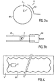
- loops B2 and B4 of monitoring device were arranged in a plane perpendicular to the "plane" of loops B1 and B3 (plane of the Figure 3b). Electromagnetic coupling between the loops is, in such an arrangement, particularly sensitive to suspension travel.
- loops B2 and B4 are arranged on a wheel arch of the vehicle (or mudguard) near loops B1 and B3. The long side of the rectangle that they form flat extends over a concentric arc with the radial carcass 3 of the tire. So the distance d between the loops arranged in the tire and on the vehicle is substantially constant at rest (figure 3a).
- This distance can vary, however, depending on the travel suspension.
- the Applicant has accordingly provided loop widths of the same order of magnitude as the distance d; a slight difference at this distance does not cause not a significant variation in the magnetic flux transmitted between buckles.
- the loops mounted on the vehicle are slightly wider than those implanted in the pneuma tick.
- the lines of fields H (FIG. 5) can browse the inside of the loops without the transmission of magnetic flux is disturbed by a possible angle of turn the wheel would take relative to the center line of the vehicle.
- the coupling losses between the loops in the example described reach around 20dB, while that they were around 30dB in the configuration described in the aforementioned patent application.
- the tire according to the invention may comprise only a single induction loop B1 making it possible to connect the active element to processing means MT, as well as to supply means MA.
- the loop B1 can cooperate with the supply loop B4 on a frequency band close to w 1 (typically 40 kHz).
- the loops are located under the radial carcass ply, which suggests that the metal structure of the carcass could induce disturbances on the transmitted flows.
- the Applicant has observed that the losses of coupling do not increase significantly in the configuration described.
- the invention allows communication electric (in the broad sense), until the supply between a tire and the chassis of a vehicle. She finds a particular application for detecting the state of a pneumatic by measuring acceleration. She is likely many variations, especially with regard to data transmitted and the physical quantity used to detect the condition of the tire.
Landscapes
- Engineering & Computer Science (AREA)
- Mechanical Engineering (AREA)
- Computer Hardware Design (AREA)
- Microelectronics & Electronic Packaging (AREA)
- Physics & Mathematics (AREA)
- General Physics & Mathematics (AREA)
- Theoretical Computer Science (AREA)
- Tires In General (AREA)
- Arrangements For Transmission Of Measured Signals (AREA)
Description
- la figure 1 représente schématiquement le pneumatique 1 selon l'invention muni de boucles conductrices B1 et B3 d'un dispositif de surveillance en service de l'état du pneumatique, dans l'exemple décrit,
- la figure 2 représente la préforme complémentaire comportant le support élastique S et la boucle conductrice B1, disposée entre les préformes respectives de la nappe de carcasse radiale 3 et de la couche d'étanchéité 4,
- la figure 3a représente schématiquement les dispositions respectives de la boucle B1 et de la boucle B2, coopérant entre elles, dans une vue de face,
- la figure 3b est une vue de dessus des éléments de la figure 3a,
- la figure 4 est une vue de dessus de la boucle B1, déroulée à plat, sur son support S,
- la figure 5 est une vue suivant la coupe V-V de la figure 3a, faisant apparaítre une partie des lignes de champ qui traversent les boucles B1 et B2, et
- la figure 6 représente le schéma électrique équivalent du couplage entre les deux boucles B1 et B2.
Claims (15)
- Procédé de fabrication d'un pneumatique (1), du type comportant les étapes suivantes:caractérisé en ce que :i - préparer une préforme déformable de la carcasse (3),ii - maintenir cette préforme enroulée sur un support de conformation générale circulaire,iii - poursuivre la fabrication du pneumatique, de manière connue en soi, avec un étirement de la préforme ainsi maintenue, dans une direction générale vers l'extérieur, ledit étirement étant effectué après solidarisation des extrémités libres de la préforme,ce qui permet d'implanter une boucle conductrice (B1) à l'intérieur du pneumatique sans modification majeure de ses techniques de fabrication.l'étape i) comprend en outre la préparation d'une préforme complémentaire comprenant un support élastique (S), de forme générale rectangulaire, homologue de celle de ladite préforme, muni d'au moins un conducteur (B1) fixé de manière lâche, également selon une forme générale rectangulaire, etl'étape ii) comprend le maintien de cette préforme complémentaire avec la préforme précitée, sur le support de conformation générale circulaire,
- Procédé selon la revendication 1, dans lequel l'étape i) comprend en outre la préparation de préformes déformables d'une couche d'étanchéité (4) et d'une nappe de carcasse radiale (3) du pneumatique,
caractérisé en ce que la préforme complémentaire est maintenue, au cours de l'étape ii), entre les deux préformes respectives de la nappe de carcasse radiale (3) et de la couche d'étanchéité (4). - Procédé selon l'une des revendications 1 et 2, caractérisé en ce que le conducteur est conformé au cours de l'étape i) pour présenter une forme générale de boucle ouverte rectangulaire (B1),
- Procédé selon la revendication 3, caractérisé en ce que les deux petits côtés de la boucle rectangulaire (B1) sont joints au cours de l'étape ii) pour être sensiblement adjacents.
- Procédé selon l'une des revendications 3 et 4, caractérisé en ce que l'étape i) comprend en outre la fixation sur le support élastique d'une autre boucle (B3), homologue de ladite boucle ouverte (B1).
- Procédé selon la revendication 5, caractérisé en ce que les boucles (B1,B3) sont fixées sur le support élastique (S) par une technique du genre surfilage ou faufilage.
- Procédé selon l'une des revendications 5 et 6, caractérisé en ce que l'étape i) comprend en outre les connexions des boucles à un élément actif, et chacune à au moins un composant électrique (C1).
- Procédé selon la revendication 7, caractérisé en ce que l'étape ii) comprend en outre l'implantation dudit élément actif sous la préforme de la carcasse (3).
- Procédé selon l'une des revendications 5 et 6, caractérisé en ce que l'on prévoit de laisser apparentes les deux extrémités libres de chaque boucle pour connecter celles-ci à un élément actif, et chacune à au moins un composant électrique (C1) après l'une des étapes ii) et iii).
- Pneumatique, caractérisé en ce qu'il comprend, fixée sous sa bande de roulement, au moins une boucle conductrice (B1) qui présente, déroulée à plat, une forme générale rectangulaire, le petit côté et le grand côté du rectangle s'étendant sensiblement sur la largeur du pneumatique et sensiblement tout le long de sa périphérie, respectivement.
- Pneumatique selon la revendication 10, caractérisé en ce que sa boucle (B1) est agencée pour être apte à coopérer par couplage électromagnétique avec au moins une boucle (B2), accordée en fréquence (w), et disposée au voisinage externe de la périphérie du pneumatique.
- Pneumatique selon la revendication 11, caractérisé en ce qu'il comporte en outre un élément actif implanté sous la bande de roulement, et connecté à la boucle précitée (B1) de sorte qu'il soit apte à transmettre des informations relatives à l'état du pneumatique.
- Pneumatique selon l'une des revendications 10 à 12, caractérisé en ce qu'il comporte une autre boucle conductrice (B3), propre à délivrer une énergie notamment électrique pour alimenter un élément actif, implanté sous la bande de roulement.
- Pneumatique selon l'une des revendications 12 et 13, caractérisé en ce que l'élément actif comporte un capteur miniature (2) disposé pour être sensible à l'accélération radiale du pneumatique.
- Pneumatique selon l'une des revendications 12 à 14, caractérisé en ce qu'il comporte une mémoire embarquée, non volatile (EEPROM), et connectée à l'élément actif.
Applications Claiming Priority (3)
| Application Number | Priority Date | Filing Date | Title |
|---|---|---|---|
| FR9715491 | 1997-12-08 | ||
| FR9715491A FR2771965B1 (fr) | 1997-12-08 | 1997-12-08 | Pneumatique muni d'une boucle conductrice et procede d'implantation de cette boucle sous sa bande de roulement |
| PCT/FR1998/002600 WO1999029495A1 (fr) | 1997-12-08 | 1998-12-02 | Pneumatique muni d'une boucle conductrice et procede d'implantation de cette boucle sous sa bande de roulement |
Publications (2)
| Publication Number | Publication Date |
|---|---|
| EP1045755A1 EP1045755A1 (fr) | 2000-10-25 |
| EP1045755B1 true EP1045755B1 (fr) | 2003-03-05 |
Family
ID=9514308
Family Applications (1)
| Application Number | Title | Priority Date | Filing Date |
|---|---|---|---|
| EP98958309A Expired - Lifetime EP1045755B1 (fr) | 1997-12-08 | 1998-12-02 | Pneumatique muni d'une boucle conductrice et procede d'implantation de cette boucle sous sa bande de roulement |
Country Status (6)
| Country | Link |
|---|---|
| EP (1) | EP1045755B1 (fr) |
| JP (1) | JP2001525270A (fr) |
| AU (1) | AU1439799A (fr) |
| DE (1) | DE69811957T2 (fr) |
| FR (1) | FR2771965B1 (fr) |
| WO (1) | WO1999029495A1 (fr) |
Families Citing this family (7)
| Publication number | Priority date | Publication date | Assignee | Title |
|---|---|---|---|---|
| US7190319B2 (en) * | 2001-10-29 | 2007-03-13 | Forster Ian J | Wave antenna wireless communication device and method |
| JP4882185B2 (ja) * | 2001-08-29 | 2012-02-22 | 日産自動車株式会社 | 車輪タイヤの接地長検出装置 |
| ES2276941T3 (es) * | 2002-03-28 | 2007-07-01 | Pirelli Tyre S.P.A. | Procedimiento y sistema para monitorizar el comportamiento de un neumatico durante la circulacion de un vehiculo a motor. |
| FR2837985B1 (fr) * | 2002-04-02 | 2004-05-21 | Commissariat Energie Atomique | Antenne receptrice morcelee |
| FR2837748A1 (fr) | 2002-04-02 | 2003-10-03 | Michelin Soc Tech | Pneumatique dote d'une antenne receptrice |
| DE10217215C5 (de) * | 2002-04-18 | 2012-04-19 | Continental Reifen Deutschland Gmbh | Einrichtung zur Überwachung und Identifizierung von Luftreifen |
| FR2891770B1 (fr) | 2005-10-06 | 2007-12-07 | Michelin Soc Tech | Procede et dispositif de mesure de pression de gonflage d'un pneumatique au moyen d'un capteur de contrainte |
Family Cites Families (8)
| Publication number | Priority date | Publication date | Assignee | Title |
|---|---|---|---|---|
| DE2524463A1 (de) * | 1975-06-03 | 1976-12-23 | Werner Breuer | Einrichtung zur anzeige der verkehrsuntuechtigkeit von kraftfahrzeugreifen |
| US4319220A (en) * | 1976-08-31 | 1982-03-09 | Dennis G. Pappas | Alarm system for monitoring pressurized vehicular tires |
| US4277296A (en) * | 1977-09-19 | 1981-07-07 | Skidmore Frank O | Pneumatic tire and method of making same |
| DE3416747A1 (de) * | 1984-05-07 | 1985-11-07 | Soolit Gummivertriebs GmbH, 6238 Hofheim | Profilierter laufstreifen fuer die laufflaechenkalterneuerung von fahrzeugluftreifen und verfahren zu seiner herstellung |
| DE69022518D1 (de) * | 1989-03-31 | 1995-10-26 | Hughes Aircraft Co | Nachweissystem für fahrzeugreifen. |
| US5181975A (en) * | 1991-03-27 | 1993-01-26 | The Goodyear Tire & Rubber Company | Integrated circuit transponder with coil antenna in a pneumatic tire for use in tire identification |
| US6062072A (en) * | 1995-08-11 | 2000-05-16 | Dynatron Ag | Device for monitoring the air pressure of pneumatic tires of vehicles |
| DE19648318B4 (de) * | 1996-11-22 | 2006-07-20 | Continental Teves Ag & Co. Ohg | Übertrager zur Übertragung elektrischer Energie zu einem Rad eines Kraftfahrzeuges |
-
1997
- 1997-12-08 FR FR9715491A patent/FR2771965B1/fr not_active Expired - Fee Related
-
1998
- 1998-12-02 EP EP98958309A patent/EP1045755B1/fr not_active Expired - Lifetime
- 1998-12-02 JP JP2000524125A patent/JP2001525270A/ja active Pending
- 1998-12-02 WO PCT/FR1998/002600 patent/WO1999029495A1/fr not_active Ceased
- 1998-12-02 AU AU14397/99A patent/AU1439799A/en not_active Abandoned
- 1998-12-02 DE DE69811957T patent/DE69811957T2/de not_active Expired - Fee Related
Also Published As
| Publication number | Publication date |
|---|---|
| AU1439799A (en) | 1999-06-28 |
| EP1045755A1 (fr) | 2000-10-25 |
| FR2771965B1 (fr) | 2000-01-14 |
| DE69811957D1 (de) | 2003-04-10 |
| WO1999029495A1 (fr) | 1999-06-17 |
| JP2001525270A (ja) | 2001-12-11 |
| FR2771965A1 (fr) | 1999-06-11 |
| DE69811957T2 (de) | 2003-10-30 |
Similar Documents
| Publication | Publication Date | Title |
|---|---|---|
| EP3548313B1 (fr) | Enveloppe pneumatique équipée d'un organe électronique | |
| EP3548314B1 (fr) | Enveloppe pneumatique équipée d'un organe électronique | |
| EP2512838B1 (fr) | Procede de fabrication d'un dispositif electronique pour pneumatique | |
| EP0296511B1 (fr) | Procédé de fabrication d'un ruban destiné à fournir des circuits pour modules électroniques, et ruban obtenu selon ce procédé | |
| EP0988160B1 (fr) | Surveillance d'un pneumatique par mesure d'acceleration | |
| EP1045755A1 (fr) | Pneumatique muni d'une boucle conductrice et procede d'implantation de cette boucle sous sa bande de roulement | |
| EP2158604A2 (fr) | Assemblage de puces radiofrequence | |
| EP2810299B1 (fr) | Procédé d'assemblage d'un élément à puce micro-électronique sur un élément filaire, installation permettant de réaliser l'assemblage | |
| WO1998059319A1 (fr) | Micromodule electronique, notamment pour carte a puce | |
| EP0252395A1 (fr) | Tringle gainée pour enveloppes de pneumatiques; procédé pour réaliser cette tringle; enveloppes de pneumatiques comportant cette tringle | |
| EP2950381B1 (fr) | Batterie intelligente avec un circuit de gestion de la tension d'alimentation, et procédé de fabrication de la batterie | |
| FR2886466A1 (fr) | Entite electronique a antenne magnetique | |
| FR2886467A1 (fr) | Entite electronique a antenne magnetique | |
| EP4292166A1 (fr) | Dispositif d'emission-reception radiofrequence et son procede de fabrication | |
| FR2710753A1 (fr) | Capteur de courant comprenant un ruban magnétorésistif et son procédé de réalisation. | |
| WO1987000389A1 (fr) | Dispositif effaceur de charges electrostatiques | |
| EP2002384A1 (fr) | Dispositif radiofrequence | |
| EP1231615A1 (fr) | Structure d'inductance intégrée | |
| EP0375505A1 (fr) | Composant électrique à report direct | |
| EP0214897A1 (fr) | Procédé de réalisation d'un enroulement torique de faibles dimensions et de géométrie optimale | |
| WO2020208132A1 (fr) | Procédé d'enrobage de dispositifs électroniques | |
| US7026720B2 (en) | Flip-chip mounted integrated circuit card element | |
| EP0921566A1 (fr) | Composant microélectromécanique, tel que microcapteur ou microactionneur reportable sur un substrat de circuit hybride | |
| EP3825917A1 (fr) | Etiquette de radio-identification | |
| EP4201712B1 (fr) | Pneumatique équipée d'un dispositif d'émission-réception radiofréquence |
Legal Events
| Date | Code | Title | Description |
|---|---|---|---|
| PUAI | Public reference made under article 153(3) epc to a published international application that has entered the european phase |
Free format text: ORIGINAL CODE: 0009012 |
|
| 17P | Request for examination filed |
Effective date: 20000512 |
|
| AK | Designated contracting states |
Kind code of ref document: A1 Designated state(s): DE FR GB IT |
|
| GRAG | Despatch of communication of intention to grant |
Free format text: ORIGINAL CODE: EPIDOS AGRA |
|
| 17Q | First examination report despatched |
Effective date: 20020418 |
|
| GRAG | Despatch of communication of intention to grant |
Free format text: ORIGINAL CODE: EPIDOS AGRA |
|
| GRAH | Despatch of communication of intention to grant a patent |
Free format text: ORIGINAL CODE: EPIDOS IGRA |
|
| GRAH | Despatch of communication of intention to grant a patent |
Free format text: ORIGINAL CODE: EPIDOS IGRA |
|
| RAP1 | Party data changed (applicant data changed or rights of an application transferred) |
Owner name: THALES SYSTEMES AEROPORTES S.A. |
|
| GRAA | (expected) grant |
Free format text: ORIGINAL CODE: 0009210 |
|
| AK | Designated contracting states |
Designated state(s): DE FR GB IT |
|
| REG | Reference to a national code |
Ref country code: GB Ref legal event code: FG4D Free format text: NOT ENGLISH |
|
| REF | Corresponds to: |
Ref document number: 69811957 Country of ref document: DE Date of ref document: 20030410 Kind code of ref document: P |
|
| GBT | Gb: translation of ep patent filed (gb section 77(6)(a)/1977) | ||
| PGFP | Annual fee paid to national office [announced via postgrant information from national office to epo] |
Ref country code: GB Payment date: 20031126 Year of fee payment: 6 |
|
| PGFP | Annual fee paid to national office [announced via postgrant information from national office to epo] |
Ref country code: FR Payment date: 20031210 Year of fee payment: 6 |
|
| PGFP | Annual fee paid to national office [announced via postgrant information from national office to epo] |
Ref country code: DE Payment date: 20031211 Year of fee payment: 6 |
|
| PLBE | No opposition filed within time limit |
Free format text: ORIGINAL CODE: 0009261 |
|
| STAA | Information on the status of an ep patent application or granted ep patent |
Free format text: STATUS: NO OPPOSITION FILED WITHIN TIME LIMIT |
|
| 26N | No opposition filed |
Effective date: 20031208 |
|
| PG25 | Lapsed in a contracting state [announced via postgrant information from national office to epo] |
Ref country code: GB Free format text: LAPSE BECAUSE OF NON-PAYMENT OF DUE FEES Effective date: 20041202 |
|
| PG25 | Lapsed in a contracting state [announced via postgrant information from national office to epo] |
Ref country code: DE Free format text: LAPSE BECAUSE OF NON-PAYMENT OF DUE FEES Effective date: 20050701 |
|
| GBPC | Gb: european patent ceased through non-payment of renewal fee |
Effective date: 20041202 |
|
| PG25 | Lapsed in a contracting state [announced via postgrant information from national office to epo] |
Ref country code: FR Free format text: LAPSE BECAUSE OF NON-PAYMENT OF DUE FEES Effective date: 20050831 |
|
| REG | Reference to a national code |
Ref country code: FR Ref legal event code: ST |
|
| PG25 | Lapsed in a contracting state [announced via postgrant information from national office to epo] |
Ref country code: IT Free format text: LAPSE BECAUSE OF NON-PAYMENT OF DUE FEES Effective date: 20051202 |