EP1045463A1 - A method of fabricating an electrochemical cell battery and an improved cell package - Google Patents
A method of fabricating an electrochemical cell battery and an improved cell package Download PDFInfo
- Publication number
- EP1045463A1 EP1045463A1 EP00400648A EP00400648A EP1045463A1 EP 1045463 A1 EP1045463 A1 EP 1045463A1 EP 00400648 A EP00400648 A EP 00400648A EP 00400648 A EP00400648 A EP 00400648A EP 1045463 A1 EP1045463 A1 EP 1045463A1
- Authority
- EP
- European Patent Office
- Prior art keywords
- enclosure
- pouch
- electrolyte
- cell
- cell stack
- Prior art date
- Legal status (The legal status is an assumption and is not a legal conclusion. Google has not performed a legal analysis and makes no representation as to the accuracy of the status listed.)
- Withdrawn
Links
- 238000004519 manufacturing process Methods 0.000 title claims abstract description 30
- 239000003792 electrolyte Substances 0.000 claims abstract description 102
- 238000007789 sealing Methods 0.000 claims abstract description 40
- 238000000034 method Methods 0.000 claims description 24
- -1 polypropylene Polymers 0.000 claims description 20
- 239000000853 adhesive Substances 0.000 claims description 18
- 230000001070 adhesive effect Effects 0.000 claims description 18
- 239000004743 Polypropylene Substances 0.000 claims description 16
- 229920001155 polypropylene Polymers 0.000 claims description 16
- 229920000728 polyester Polymers 0.000 claims description 12
- 229910052782 aluminium Inorganic materials 0.000 claims description 11
- XAGFODPZIPBFFR-UHFFFAOYSA-N aluminium Chemical compound [Al] XAGFODPZIPBFFR-UHFFFAOYSA-N 0.000 claims description 11
- 230000004888 barrier function Effects 0.000 claims description 8
- 230000015572 biosynthetic process Effects 0.000 claims description 6
- 229920001187 thermosetting polymer Polymers 0.000 claims description 5
- 229920002635 polyurethane Polymers 0.000 claims description 3
- 239000004814 polyurethane Substances 0.000 claims description 3
- 239000006185 dispersion Substances 0.000 claims description 2
- 230000009172 bursting Effects 0.000 claims 1
- 239000010410 layer Substances 0.000 description 41
- 239000011888 foil Substances 0.000 description 10
- 239000000463 material Substances 0.000 description 8
- 238000007872 degassing Methods 0.000 description 6
- 239000005022 packaging material Substances 0.000 description 6
- 239000002904 solvent Substances 0.000 description 6
- 239000012790 adhesive layer Substances 0.000 description 5
- 238000011109 contamination Methods 0.000 description 5
- 239000004698 Polyethylene Substances 0.000 description 4
- XLYOFNOQVPJJNP-UHFFFAOYSA-N water Substances O XLYOFNOQVPJJNP-UHFFFAOYSA-N 0.000 description 4
- 238000010276 construction Methods 0.000 description 3
- 229910052751 metal Inorganic materials 0.000 description 3
- 239000002184 metal Substances 0.000 description 3
- 230000035699 permeability Effects 0.000 description 3
- PXHVJJICTQNCMI-UHFFFAOYSA-N Nickel Chemical compound [Ni] PXHVJJICTQNCMI-UHFFFAOYSA-N 0.000 description 2
- 238000004891 communication Methods 0.000 description 2
- 238000005470 impregnation Methods 0.000 description 2
- 229920000573 polyethylene Polymers 0.000 description 2
- RYGMFSIKBFXOCR-UHFFFAOYSA-N Copper Chemical compound [Cu] RYGMFSIKBFXOCR-UHFFFAOYSA-N 0.000 description 1
- OIFBSDVPJOWBCH-UHFFFAOYSA-N Diethyl carbonate Chemical compound CCOC(=O)OCC OIFBSDVPJOWBCH-UHFFFAOYSA-N 0.000 description 1
- KMTRUDSVKNLOMY-UHFFFAOYSA-N Ethylene carbonate Chemical compound O=C1OCCO1 KMTRUDSVKNLOMY-UHFFFAOYSA-N 0.000 description 1
- 229910001290 LiPF6 Inorganic materials 0.000 description 1
- WHXSMMKQMYFTQS-UHFFFAOYSA-N Lithium Chemical compound [Li] WHXSMMKQMYFTQS-UHFFFAOYSA-N 0.000 description 1
- 229920003182 Surlyn® Polymers 0.000 description 1
- 239000005035 Surlyn® Substances 0.000 description 1
- 238000004026 adhesive bonding Methods 0.000 description 1
- 230000008859 change Effects 0.000 description 1
- 239000011248 coating agent Substances 0.000 description 1
- 238000000576 coating method Methods 0.000 description 1
- 239000000356 contaminant Substances 0.000 description 1
- 229910052802 copper Inorganic materials 0.000 description 1
- 239000010949 copper Substances 0.000 description 1
- 238000005520 cutting process Methods 0.000 description 1
- 230000032798 delamination Effects 0.000 description 1
- IEJIGPNLZYLLBP-UHFFFAOYSA-N dimethyl carbonate Chemical compound COC(=O)OC IEJIGPNLZYLLBP-UHFFFAOYSA-N 0.000 description 1
- 239000012530 fluid Substances 0.000 description 1
- 239000007789 gas Substances 0.000 description 1
- 239000003292 glue Substances 0.000 description 1
- 238000010438 heat treatment Methods 0.000 description 1
- 239000012793 heat-sealing layer Substances 0.000 description 1
- 239000012943 hotmelt Substances 0.000 description 1
- 238000001746 injection moulding Methods 0.000 description 1
- 230000002452 interceptive effect Effects 0.000 description 1
- 229910052744 lithium Inorganic materials 0.000 description 1
- 230000007246 mechanism Effects 0.000 description 1
- 239000000203 mixture Substances 0.000 description 1
- 229910052759 nickel Inorganic materials 0.000 description 1
- 239000005486 organic electrolyte Substances 0.000 description 1
- 239000003960 organic solvent Substances 0.000 description 1
- 238000004806 packaging method and process Methods 0.000 description 1
- 230000000149 penetrating effect Effects 0.000 description 1
- 229920000642 polymer Polymers 0.000 description 1
- 230000008569 process Effects 0.000 description 1
- 238000005096 rolling process Methods 0.000 description 1
- 230000035939 shock Effects 0.000 description 1
- 238000003860 storage Methods 0.000 description 1
- 238000003466 welding Methods 0.000 description 1
Images





Classifications
-
- H—ELECTRICITY
- H01—ELECTRIC ELEMENTS
- H01M—PROCESSES OR MEANS, e.g. BATTERIES, FOR THE DIRECT CONVERSION OF CHEMICAL ENERGY INTO ELECTRICAL ENERGY
- H01M50/00—Constructional details or processes of manufacture of the non-active parts of electrochemical cells other than fuel cells, e.g. hybrid cells
- H01M50/50—Current conducting connections for cells or batteries
- H01M50/543—Terminals
- H01M50/552—Terminals characterised by their shape
- H01M50/553—Terminals adapted for prismatic, pouch or rectangular cells
- H01M50/557—Plate-shaped terminals
-
- H—ELECTRICITY
- H01—ELECTRIC ELEMENTS
- H01M—PROCESSES OR MEANS, e.g. BATTERIES, FOR THE DIRECT CONVERSION OF CHEMICAL ENERGY INTO ELECTRICAL ENERGY
- H01M50/00—Constructional details or processes of manufacture of the non-active parts of electrochemical cells other than fuel cells, e.g. hybrid cells
- H01M50/10—Primary casings; Jackets or wrappings
- H01M50/116—Primary casings; Jackets or wrappings characterised by the material
- H01M50/117—Inorganic material
- H01M50/119—Metals
-
- H—ELECTRICITY
- H01—ELECTRIC ELEMENTS
- H01M—PROCESSES OR MEANS, e.g. BATTERIES, FOR THE DIRECT CONVERSION OF CHEMICAL ENERGY INTO ELECTRICAL ENERGY
- H01M50/00—Constructional details or processes of manufacture of the non-active parts of electrochemical cells other than fuel cells, e.g. hybrid cells
- H01M50/10—Primary casings; Jackets or wrappings
- H01M50/116—Primary casings; Jackets or wrappings characterised by the material
- H01M50/121—Organic material
-
- H—ELECTRICITY
- H01—ELECTRIC ELEMENTS
- H01M—PROCESSES OR MEANS, e.g. BATTERIES, FOR THE DIRECT CONVERSION OF CHEMICAL ENERGY INTO ELECTRICAL ENERGY
- H01M50/00—Constructional details or processes of manufacture of the non-active parts of electrochemical cells other than fuel cells, e.g. hybrid cells
- H01M50/10—Primary casings; Jackets or wrappings
- H01M50/116—Primary casings; Jackets or wrappings characterised by the material
- H01M50/124—Primary casings; Jackets or wrappings characterised by the material having a layered structure
- H01M50/126—Primary casings; Jackets or wrappings characterised by the material having a layered structure comprising three or more layers
- H01M50/129—Primary casings; Jackets or wrappings characterised by the material having a layered structure comprising three or more layers with two or more layers of only organic material
-
- H—ELECTRICITY
- H01—ELECTRIC ELEMENTS
- H01M—PROCESSES OR MEANS, e.g. BATTERIES, FOR THE DIRECT CONVERSION OF CHEMICAL ENERGY INTO ELECTRICAL ENERGY
- H01M50/00—Constructional details or processes of manufacture of the non-active parts of electrochemical cells other than fuel cells, e.g. hybrid cells
- H01M50/10—Primary casings; Jackets or wrappings
- H01M50/131—Primary casings; Jackets or wrappings characterised by physical properties, e.g. gas permeability, size or heat resistance
- H01M50/133—Thickness
-
- H—ELECTRICITY
- H01—ELECTRIC ELEMENTS
- H01M—PROCESSES OR MEANS, e.g. BATTERIES, FOR THE DIRECT CONVERSION OF CHEMICAL ENERGY INTO ELECTRICAL ENERGY
- H01M50/00—Constructional details or processes of manufacture of the non-active parts of electrochemical cells other than fuel cells, e.g. hybrid cells
- H01M50/50—Current conducting connections for cells or batteries
- H01M50/543—Terminals
- H01M50/547—Terminals characterised by the disposition of the terminals on the cells
- H01M50/55—Terminals characterised by the disposition of the terminals on the cells on the same side of the cell
-
- H—ELECTRICITY
- H01—ELECTRIC ELEMENTS
- H01M—PROCESSES OR MEANS, e.g. BATTERIES, FOR THE DIRECT CONVERSION OF CHEMICAL ENERGY INTO ELECTRICAL ENERGY
- H01M50/00—Constructional details or processes of manufacture of the non-active parts of electrochemical cells other than fuel cells, e.g. hybrid cells
- H01M50/60—Arrangements or processes for filling or topping-up with liquids; Arrangements or processes for draining liquids from casings
-
- Y—GENERAL TAGGING OF NEW TECHNOLOGICAL DEVELOPMENTS; GENERAL TAGGING OF CROSS-SECTIONAL TECHNOLOGIES SPANNING OVER SEVERAL SECTIONS OF THE IPC; TECHNICAL SUBJECTS COVERED BY FORMER USPC CROSS-REFERENCE ART COLLECTIONS [XRACs] AND DIGESTS
- Y02—TECHNOLOGIES OR APPLICATIONS FOR MITIGATION OR ADAPTATION AGAINST CLIMATE CHANGE
- Y02E—REDUCTION OF GREENHOUSE GAS [GHG] EMISSIONS, RELATED TO ENERGY GENERATION, TRANSMISSION OR DISTRIBUTION
- Y02E60/00—Enabling technologies; Technologies with a potential or indirect contribution to GHG emissions mitigation
- Y02E60/10—Energy storage using batteries
-
- Y—GENERAL TAGGING OF NEW TECHNOLOGICAL DEVELOPMENTS; GENERAL TAGGING OF CROSS-SECTIONAL TECHNOLOGIES SPANNING OVER SEVERAL SECTIONS OF THE IPC; TECHNICAL SUBJECTS COVERED BY FORMER USPC CROSS-REFERENCE ART COLLECTIONS [XRACs] AND DIGESTS
- Y02—TECHNOLOGIES OR APPLICATIONS FOR MITIGATION OR ADAPTATION AGAINST CLIMATE CHANGE
- Y02P—CLIMATE CHANGE MITIGATION TECHNOLOGIES IN THE PRODUCTION OR PROCESSING OF GOODS
- Y02P70/00—Climate change mitigation technologies in the production process for final industrial or consumer products
- Y02P70/50—Manufacturing or production processes characterised by the final manufactured product
-
- Y—GENERAL TAGGING OF NEW TECHNOLOGICAL DEVELOPMENTS; GENERAL TAGGING OF CROSS-SECTIONAL TECHNOLOGIES SPANNING OVER SEVERAL SECTIONS OF THE IPC; TECHNICAL SUBJECTS COVERED BY FORMER USPC CROSS-REFERENCE ART COLLECTIONS [XRACs] AND DIGESTS
- Y10—TECHNICAL SUBJECTS COVERED BY FORMER USPC
- Y10T—TECHNICAL SUBJECTS COVERED BY FORMER US CLASSIFICATION
- Y10T29/00—Metal working
- Y10T29/49—Method of mechanical manufacture
- Y10T29/49002—Electrical device making
- Y10T29/49108—Electric battery cell making
-
- Y—GENERAL TAGGING OF NEW TECHNOLOGICAL DEVELOPMENTS; GENERAL TAGGING OF CROSS-SECTIONAL TECHNOLOGIES SPANNING OVER SEVERAL SECTIONS OF THE IPC; TECHNICAL SUBJECTS COVERED BY FORMER USPC CROSS-REFERENCE ART COLLECTIONS [XRACs] AND DIGESTS
- Y10—TECHNICAL SUBJECTS COVERED BY FORMER USPC
- Y10T—TECHNICAL SUBJECTS COVERED BY FORMER US CLASSIFICATION
- Y10T29/00—Metal working
- Y10T29/49—Method of mechanical manufacture
- Y10T29/49002—Electrical device making
- Y10T29/49108—Electric battery cell making
- Y10T29/4911—Electric battery cell making including sealing
Definitions
- the present invention relates to a method of fabricating an electrochemical battery and, more particularly, to a method of injecting the electrolyte into the cell stack of the battery by first placing the electrolyte in a sealed pouch that is placed together with the cell stack into a cell package.
- the invention also relates to a cell package which can be heat sealed even after it has been contaminated during the process of introducing the electrolyte into the cell stack.
- a important consideration in the manufacturing of electrochemical batteries is the manner in which the electrolyte is introduced into the cell stack.
- a current technique includes the steps of pouring the electrolyte into the cell stack during the manufacturing of the cell stack in a machine, placing the electrolyte impregnated cell stack into the cell package, evacuating the cell package and heat sealing the package.
- the first problem is the loss of electrolyte during the step of pouring the electrolyte into the cell stack and the subsequent step of evacuating the package. It is estimated that between 10 and 30% of the electrolyte is lost during these steps.
- the electrolyte is a relatively expensive component of the electrochemical cell. Thus, the loss of electrolyte increases the overall cost of manufacturing the battery. Further, since the amount of lost electrolyte cannot be gauged, the final volume of electrolyte that remains in the cell stack is unknown.
- a second problem is that the electrolyte that is naturally suctioned from the cell stack during the evacuating step contaminates the inside of the package. Such contamination of the package makes it difficult to securely seal the package. As such, subsequent leakage of the electrolyte from the sealed package may result.
- the pouring step must be performed in a glove box environment (i.e., dry and inert atmosphere) . Since this step is an intermediate step in the manufacturing of the cell stack, the machine which manufactures the cell stack must consequently have a glove box environment, thus driving up the cost of the machine.
- the electrolyte when the electrolyte is poured into the cell stack, the electrolyte contaminates the machine thus requiring that it be cleaned on a regular basis.
- the vacuum that is applied to the cell stack during the evacuating step may change the solvent ratio of the impregnated electrolyte.
- the current cell package is formed of a laminate of a polyester outer layer, an aluminum barrier layer and a polyethylene acrylic acid (EAA) inner layer.
- the polyester layer provides, strength, the aluminum layer prevents water from penetrating the cell package and the inner layer allows for the heat sealing of the cell package.
- the cell package includes two parts that are bonded together around their periphery by heating sealing the EAA inner layers to each other.
- the problem with this laminate is that once contaminated with electrolyte, the EAA inner layers cannot form a secure heat seal. This makes degassing and resealing of the cell package a problem.
- the current material has a relatively high permeability to water necessitating the use of wider heat sealing areas in order to ensure a long shelf life.
- the current laminate will absorb electrolyte at elevated temperatures which can interact with the adhesive layer between the EAA inner layer and the aluminum barrier layer.
- an object of the invention is to provide a method of manufacturing an electrochemical battery which overcomes the above problems.
- an object of the invention is to provide a method of manufacturing a battery where the electrolyte is introduced into the cell stack with minimal or no loss of electrolyte.
- Another object of the invention is to provide a method in which the electrolyte filling step is performed after the cell stack is manufactured so that the cell stack manufacturing machine does not have to maintain a glove box environment and contamination of the machine is eliminated.
- a method of fabricating an electrochemical battery comprising the steps of separately forming an electrode cell stack and a sealed electrolyte pouch, placing the cell stack and the electrolyte pouch together into a cell package, applying a vacuum to the cell package, sealing the cell package, and rupturing the pouch to release the electrolyte into the cell stack.
- the rupturing step includes the step of squeezing the pouch until the electrolyte squirts out of the pouch.
- the sealing step includes the step of heat sealing the cell package.
- Another aspect of the invention is to form the cell package so that it includes two separate enclosures with a tube extending between the two enclosures such that they communicate with each other through the tube.
- the cell stack is placed in a first one of the enclosures which is then evacuated.
- the sealed electrolyte pouch is placed in the second enclosure which is also evacuated after the pouch is inserted. Thereafter, as with the previous embodiment, the pouch is ruptured to release the electrolyte from the pouch such that it flows through the tube and into the cell stack contained in the first enclosure.
- the tube is then sealed and the second enclosure is removed.
- the degassing step is performed by puncturing the second enclosure and applying a vacuum thereto so that the first enclosure is degassed via the tube. The tube is then sealed and the second enclosure is removed.
- a laminate which includes a polyester outer layer, an aluminum barrier layer and a polypropylene inner layer which are adhered together using a unique adhesive which does not break down when contaminated with electrolyte. It has been discovered that the polypropylene layers associated with the overlapped portions of the cell package can be securely heat sealed to each other even when contaminated with electrolyte.
- an electrolyte 8 is first introduced into a pouch 10 and the pouch is evacuated and sealed.
- the sealed pouch is then placed along with a pre-manufactured cell stack 12 inside a cell package 14 which is then evacuated and sealed. Thereafter, the sealed pouch 10 is ruptured so that the electrolyte is released from the open end 16 of the pouch and impregnated inside the cell stack 12.
- the electrolyte pouch 10 is illustrated in Figs. 1 and 2.
- the pouch is made of a polyethylene film or the like having, for example, a thickness of 50 ⁇ , and is formed by folding the film in half and heat sealing the two longitudinal sides 18 to form heat sealed seams 19.
- the bottom end 20 of the pouch is closed by virtue of the fold while the top end of the pouch 22 is initially open (Fig. 1 shows the pouch after the electrolyte has been inserted and the pouch completely sealed).
- the pouch can be formed by folding the film along the length of the film and heat sealing the longitudinal side opposite the fold and the bottom.
- the pouch can be formed so it is seamless with an open top.
- the pouch can be formed of two separate sheets which are heat sealed together.
- the next step is to fill the pouch 10 with a predetermined amount of electrolyte.
- This step is preferably conducted in a glove box having a dry and inert atmosphere and using a dropper.
- the top 22 of the pouch 10 is heat sealed in a condition that there are no air bubbles inside the pouch.
- One technique to accomplish this is to seal the pouch just below the top level of the electrolyte, although the invention is no so limited. This ensures that all of the air is removed from the pouch prior to sealing.
- the excess portion of the pouch i.e., above the seal
- the top edge is cleaned to remove the electrolyte on the outside of the pouch so as to avoid subsequent contamination.
- the electrolyte pouch 10 is now ready to be inserted into the cell package 14.
- the cell stack 12 is positioned inside the cell package 14 with its leads 24 extending outside the package 14.
- the package can be formed by folding the film in either the longitudinal or transverse direction and heat sealing two of the remaining three sides to leave one end open. Since the leads must be accessible from the exterior of the cell package, the cell package should be folded and heat sealed around the cell stack.
- the cell package has been formed by folding the film along a longitudinal side 26 to cover the cell stack and thereafter heat sealing the opposite longitudinal side 28 and the top end 30 around the leads 24. This leaves the bottom end 32 of the cell package open.
- the cell package can be formed from two separate sheets 31 which are heat sealed together, as shown in Fig. 11, and discussed in greater detail below.
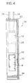
- the pouch 10 is inserted into the cell package 14 through the open bottom end 32. It is preferred that the pouch 10 be positioned so that a sealed end (e.g., the top end 22) of the pouch is closest to the cell stack, as shown.
- the cell package 14 is then evacuated and the open bottom end 32 of the package 14 is heat sealed, as designated by reference numeral 34. This results in an evacuated cell package 14 with the cell stack 12 and the electrolyte pouch 10 located inside.
- the pouch 10 is then ruptured to release the electrolyte from the pouch. Since the cell package 14 is evacuated, the released electrolyte is suctioned inside the cell package to activate the cell stack 12.
- a preferred technique for rupturing the pouch is to apply a sufficient pressure to the pouch to burst the pouch. It is important that the technique used for rupturing the cell does not rupture the package.
- the top, heat sealed, end 22 of the pouch, closest to the cell stack is ruptured. This is achieved by rolling a roller (not shown) along the pouch starting from the bottom end 20 and proceeding toward the top end 22 or by applying a mechanical shock to the pouch.
- the cell package 14 is formed so that it includes two enclosure that are separated from each other.
- a first enclosure 50 has a cell stack cup 52 which is sized to receive the cell stack 12 and the second enclosure 54 has a pouch cup 56 which is sized to receive the electrolyte pouch 10, discussed above.
- the cell package 14 is vacuum heat sealed along seams 58, as shown in Figs 6 and 7 and discussed further below, so as to form the two enclosures.
- a tube 60 is provided inside the cell package 14 so that one end communicates with the cell stack cup 52 and the other end communicates with the pouch cup 56.
- the two cups are in fluid communication with each other.
- a window 62 is provided in the cell package 14 between the two enclosures such that a portion 64 of the tube is exposed to the outside of the cell package to allow the tube to be ultra-sonically welded without interfering with the package.
- the cell package 14 is formed from two sheets of packaging material that are heat sealed together along the seams 58 in a conventional manner.
- the tube Prior to sealing the transverse seams 66, the tube is positioned between the sheets with respective ends in communication with the cell stack cup 52 and the pouch cup 56. Thereafter, the package is heat sealed to form the transverse seams.
- the tube 60 is made of an annealed metal, preferably nickel, copper, aluminum or any other material that is electrochemically compatible and weldable. Further, it is preferable that the tube be no thicker than the leads.
- the tube can be circular, oval or the like. Since the tube is made of metal, as discussed below, the heat sealing of the cell package does not cause the tube to be sealed.
- the cell stack 12 is provided in the cell stack cup 52 such that its leads extend to the exterior of the cell package 14.
- the cell package 14 is sealed around the leads 24 and evacuated, as discussed above.
- the electrolyte pouch 10 is provided in the pouch cup 56 in the second enclosure 54 and the second enclosure is evacuated.
- the cell package 14 is completely sealed without the presence of free electrolyte. Therefore, the cell package is not contaminated with the electrolyte when it is sealed.
- the electrolyte pouch 10 is then ruptured in the manner discussed above.
- the electrolyte is released from the pouch 10, flows through the tube 60, and becomes impregnated in the cell stack 12 to thereby activate the cell.
- the cell stack 14 is then subjected to formation which causes gases to develop inside the first and second enclosures 50, 54 and the cell stack cup 52 and pouch cup 56, which communicate with each other.
- the second enclosure 54 containing the burst electrolyte pouch is punctured to form hole 68 and evacuated by drawing a vacuum as designated by arrow V in Fig. 7.
- the electrolyte gasses are evacuated from the enclosures.
- the tube is sealed at seam 70 in the window 62.
- the tube 60 is ultra-sonically welded so that contaminants are removed from the weld area.
- the invention is not to be limited in this respect, it being understood that any convention welding technique would suffice.
- the cell package is trimmed to remove the second enclosure portion.
- the tube 60 is then folded back over the side of the cell package 14 so that it does not protrude from the package.
- Fig. 9 illustrates one technique for forming the tube 60.
- the tube 60 is formed by a thin metallic sheet. The sheet is folded such that the inside surfaces of the sheet contact each other and are welded together at weld area 72.
- the tube could be formed by injection molding or the like so that it is seamless, much like a hollow needle.
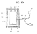
- Fig. 10 The following is a description of yet another embodiment of the invention illustrated in Fig. 10.
- a single enclosure 50 for receiving the cell stack 14 and supply the electrolyte from an external source through the tube 60 which communicates with the single enclosure 50.
- one end of the tube extends into the cell stack cup 52 in the first enclosure 50 and the other end of the tube 60 extends outside the cell package so as to be exposed.
- the exposed end of the tube 60 may then be connected to an electrolyte reservoir 80 via a three-way pump 82 which allows the enclosure to first be evacuated and then filled with the electrolyte.
- the tube is sealed and the cell is then subjected to formation.
- the tube is cut to allow for degassing by drawing a vacuum through the tube. After degassing, the tube is US welded a second time. The tube is then folded over the cell package.
- Figs. 11 and 12 show the construction of the preferred cell package 14, although the above methods are not limited to the use of this particular package.
- One of the sheets 31 has a cavity corresponding to the cell stack cup 52.
- the material of the sheets 31 includes a polyester layer 37, an Al (Aluminum) foil layer 38 and a polypropylene heat seal layer 40.
- the polyester layer 37 is adhered to the Al foil layer 38 by adhesive 42 and the heat seal layer 40 is adhered to the Al foil layer using thermoset adhesive 44.
- the polyester layer 37 provides mechanical strength, the Al foil layer 38 acts as a moisture barrier to prevent moisture from entering into the cell package and the heat seal layer 40 seals the cell package.
- the thickness of the heat seal layer is between 25 ⁇ and 100 ⁇ , and preferably between 50 ⁇ and 75 ⁇ .
- the primary purpose of the heat seal layer is to seal the cell package after the electrolyte has been impregnated into the cell stack 12.
- Polypropylene has a good compatibility with the electrolyte so that it can be heat sealed even when the cell package is contaminated with the electrolyte.
- the edge does not have an Al foil layer 38 to act as a barrier.
- the heat seal layer 40 have low permeability for both water and the electrolyte to ensure a long shelf life. Because of the non-polar nature of polypropylene it has a lower moisture permeability than the polyethylene, polyethylene acrylic acid (EAA) and SurlynTM, which, as discussed above, are current packaging materials for lithium polymer batteries. Also, polypropylene is more resistant to organic solvents than these materials.
- the adhesive 42 i.e., aqueous or solvent based adhesive.
- the adhesive 44 is preferably a thermoset polyurethane adhesive or an organosol type modified polypropylene dispersion adhesive (Morprime® 10B), both available from Morton International, Inc. These adhesives are advantageous in that they will not break down in the event the electrolyte penetrates through the polypropylene heat seal layer 40 during extended use or storage of the battery. A conventional water or solvent based adhesive can be attacked by the electrolyte.
- test results demonstrate the improved strength associated with these adhesives 44. Specifically, a test was conducted to compare the seal strength of the cell package of the present invention (in both the uncontaminated state and the contaminated state) with the current cell package.
- Strips were cut of each packaging material and they were heat sealed together to form pouches.
- a first group of pouches were filled with organic electrolyte composed of a mixture of dimethylcarbonate, diethylcarbonate, ethylenecarbonate, and LiPF 6 . They were subsequent stored for 4 days at 60°C. 20 mm strips were then cut from the pouches so the heat seal area was in one end. The two pieces of packaging material, which previously made up the sides of the pouch were then pulled apart at a 180° angle, and the force and failure mechanism were determined.
- a second group of pouches were subjected to the tension test without being contaminated.
- the cell package material of the present invention provides superior strength as compared to the conventional cell package, both when contaminated with electrolyte and when uncontaminated.
- the Al foil layer should be thick enough to avoid pinholes, preferably in the range of 25 ⁇ to 75 ⁇ . In the event that the cell package must be preformed, a formable grade Al foil should be used.
- the outer polyester layer 37 is designed to provide mechanical strength to the cell package 14. It should be understood that the invention is not limited to the use of polyester for this layer. For example, a laminate of PET and PE could be used as an alternative.
- the methods of the present invention provides the following important advantages. First, since the cell stack is sealed at the time that the pouch is ruptured, there is minimal loss of electrolyte. Also, there is no contamination of the equipment. Further, since the cell package is evacuated prior to the rupturing of the electrolyte pouch, electrolyte loss is further eliminate as it will not be suctioned from the cell stack. Further, the only step that must be performed in a glove box (i.e., a dry and inert atmosphere) is the filling of the pouch with electrolyte and the subsequent sealing of the pouch. The remaining assembly process steps can be performed in a dry room. Therefore, the equipment used for manufacturing the cell stack is less costly. Further, since the vacuum is applied to the package cell under the condition that the pouch is sealed inside the package, a higher vacuum pressure can be applied to ensure deep impregnation of the electrolyte into the cell stack without risking loss of electrolyte.
- the cell package construction with the polypropylene heat sealing layer and the special adhesive enables the cell package to be heat sealed after the impregnation of the electrolyte, using the first method described above, and retains its integrity even when contaminated by electrolyte. Therefore, additional steps associated with transferring the electrode stack to another, uncontaminated cell package can be eliminated.
Landscapes
- Chemical & Material Sciences (AREA)
- Chemical Kinetics & Catalysis (AREA)
- Electrochemistry (AREA)
- General Chemical & Material Sciences (AREA)
- Inorganic Chemistry (AREA)
- Sealing Battery Cases Or Jackets (AREA)
- Secondary Cells (AREA)
- Filling, Topping-Up Batteries (AREA)
Abstract
The invention provides a method of fabricating an electrochemical battery, comprising the following steps: forming an electrode cell stack (12) and an enclosure (14); placing said cell stack and a sealed electrolyte pouch (10) together into said enclosure; applying a vacuum to said enclosure; sealing said enclosure; and rupturing said pouch to release said electrolyte (8) into said cell stack. <IMAGE>
Description
The present invention relates to a method of fabricating an electrochemical
battery and, more particularly, to a method of injecting the electrolyte into the cell
stack of the battery by first placing the electrolyte in a sealed pouch that is placed
together with the cell stack into a cell package. The invention also relates to a cell
package which can be heat sealed even after it has been contaminated during the
process of introducing the electrolyte into the cell stack.
A important consideration in the manufacturing of electrochemical batteries is
the manner in which the electrolyte is introduced into the cell stack. A current
technique includes the steps of pouring the electrolyte into the cell stack during the
manufacturing of the cell stack in a machine, placing the electrolyte impregnated cell
stack into the cell package, evacuating the cell package and heat sealing the package.
This technique suffers from many disadvantages. The first problem is the loss
of electrolyte during the step of pouring the electrolyte into the cell stack and the
subsequent step of evacuating the package. It is estimated that between 10 and 30%
of the electrolyte is lost during these steps. The electrolyte is a relatively expensive
component of the electrochemical cell. Thus, the loss of electrolyte increases the
overall cost of manufacturing the battery. Further, since the amount of lost electrolyte
cannot be gauged, the final volume of electrolyte that remains in the cell stack is
unknown.
A second problem is that the electrolyte that is naturally suctioned from the
cell stack during the evacuating step contaminates the inside of the package. Such
contamination of the package makes it difficult to securely seal the package. As such,
subsequent leakage of the electrolyte from the sealed package may result. A further
problem is that the pouring step must be performed in a glove box environment (i.e.,
dry and inert atmosphere) . Since this step is an intermediate step in the
manufacturing of the cell stack, the machine which manufactures the cell stack must
consequently have a glove box environment, thus driving up the cost of the machine.
In addition, when the electrolyte is poured into the cell stack, the electrolyte
contaminates the machine thus requiring that it be cleaned on a regular basis. In
addition, the vacuum that is applied to the cell stack during the evacuating step may
change the solvent ratio of the impregnated electrolyte.
The current cell package is formed of a laminate of a polyester outer layer, an
aluminum barrier layer and a polyethylene acrylic acid (EAA) inner layer. The
polyester layer provides, strength, the aluminum layer prevents water from
penetrating the cell package and the inner layer allows for the heat sealing of the cell
package. Specifically, generally, the cell package includes two parts that are bonded
together around their periphery by heating sealing the EAA inner layers to each other.
The problem with this laminate is that once contaminated with electrolyte, the EAA
inner layers cannot form a secure heat seal. This makes degassing and resealing of
the cell package a problem. Also, the current material has a relatively high
permeability to water necessitating the use of wider heat sealing areas in order to
ensure a long shelf life. Finally, the current laminate will absorb electrolyte at
elevated temperatures which can interact with the adhesive layer between the EAA
inner layer and the aluminum barrier layer.
It is an object of the invention to provide a method of manufacturing an
electrochemical battery which overcomes the above problems. In particular, an object
of the invention is to provide a method of manufacturing a battery where the
electrolyte is introduced into the cell stack with minimal or no loss of electrolyte.
Another object of the invention is to provide a method in which the electrolyte filling
step is performed after the cell stack is manufactured so that the cell stack
manufacturing machine does not have to maintain a glove box environment and
contamination of the machine is eliminated.
These and other objects are achieved by a method of fabricating an
electrochemical battery, comprising the steps of separately forming an electrode cell
stack and a sealed electrolyte pouch, placing the cell stack and the electrolyte pouch
together into a cell package, applying a vacuum to the cell package, sealing the cell
package, and rupturing the pouch to release the electrolyte into the cell stack. The
rupturing step includes the step of squeezing the pouch until the electrolyte squirts
out of the pouch. Further, the sealing step includes the step of heat sealing the cell
package.
With this fabrication technique there is no electrolyte loss. In particular, since
the electrolyte is injected into the electrode cell stack after the package has been
sealed, substantially all of the electrolyte is suctioned into the electrode cell stack
without any of the electrolyte escaping from the package. In addition, since the
electrolyte is not poured into the cell stack during the manufacturing of the cell stack,
the cell manufacturing machine does not have to provide a glove box environment.
Also, contamination of the machine is avoided. Accordingly, all of the disadvantages
discussed above with respect to the current technique are overcome.
Another aspect of the invention is to form the cell package so that it includes
two separate enclosures with a tube extending between the two enclosures such that
they communicate with each other through the tube. The cell stack is placed in a first
one of the enclosures which is then evacuated. The sealed electrolyte pouch is placed
in the second enclosure which is also evacuated after the pouch is inserted.
Thereafter, as with the previous embodiment, the pouch is ruptured to release the
electrolyte from the pouch such that it flows through the tube and into the cell stack
contained in the first enclosure. The tube is then sealed and the second enclosure is
removed.
Also, with this technique, after formation it is possible to degas the first
enclosure. The formation is naturally done after the electrolyte has been released into
the cell stack. The degassing step is performed by puncturing the second enclosure
and applying a vacuum thereto so that the first enclosure is degassed via the tube.
The tube is then sealed and the second enclosure is removed.
It is a further object of the invention to provide a cell package made of a
laminate which can be heat sealed even when the cell package is contaminated with
electrolyte. This is achieved by a laminate which includes a polyester outer layer, an
aluminum barrier layer and a polypropylene inner layer which are adhered together
using a unique adhesive which does not break down when contaminated with
electrolyte. It has been discovered that the polypropylene layers associated with the
overlapped portions of the cell package can be securely heat sealed to each other even
when contaminated with electrolyte.
The above and other objects, features and advantages of the present invention
will be better understood from the following specification when read in conjunction
with the accompanying drawings in which:
Referring to Figs. 1-4, according to a first embodiment of the invention, an
electrolyte 8 is first introduced into a pouch 10 and the pouch is evacuated and sealed.
The sealed pouch is then placed along with a pre-manufactured cell stack 12 inside a
cell package 14 which is then evacuated and sealed. Thereafter, the sealed pouch 10
is ruptured so that the electrolyte is released from the open end 16 of the pouch and
impregnated inside the cell stack 12.
In more detail, the electrolyte pouch 10 is illustrated in Figs. 1 and 2. The
pouch is made of a polyethylene film or the like having, for example, a thickness of
50 µ, and is formed by folding the film in half and heat sealing the two longitudinal
sides 18 to form heat sealed seams 19. The bottom end 20 of the pouch is closed by
virtue of the fold while the top end of the pouch 22 is initially open (Fig. 1 shows the
pouch after the electrolyte has been inserted and the pouch completely sealed). There
are, of course, alternative techniques for forming the pouch. For example, the pouch
can be formed by folding the film along the length of the film and heat sealing the
longitudinal side opposite the fold and the bottom. Also, the pouch can be formed so
it is seamless with an open top. Alternatively, the pouch can be formed of two
separate sheets which are heat sealed together.
The next step is to fill the pouch 10 with a predetermined amount of
electrolyte. This step is preferably conducted in a glove box having a dry and inert
atmosphere and using a dropper. After the pouch 10 is filled, the top 22 of the pouch
10 is heat sealed in a condition that there are no air bubbles inside the pouch. One
technique to accomplish this is to seal the pouch just below the top level of the
electrolyte, although the invention is no so limited. This ensures that all of the air is
removed from the pouch prior to sealing. After the top 22 of the pouch 10 is heat
sealed, the excess portion of the pouch (i.e., above the seal) is removed by cutting the
pouch just above the seal. Thereafter, the top edge is cleaned to remove the
electrolyte on the outside of the pouch so as to avoid subsequent contamination. The
electrolyte pouch 10 is now ready to be inserted into the cell package 14.
Referring to Fig. 3, the cell stack 12 is positioned inside the cell package 14
with its leads 24 extending outside the package 14. Like the pouch, the package can
be formed by folding the film in either the longitudinal or transverse direction and
heat sealing two of the remaining three sides to leave one end open. Since the leads
must be accessible from the exterior of the cell package, the cell package should be
folded and heat sealed around the cell stack. In the illustrated embodiment, the cell
package has been formed by folding the film along a longitudinal side 26 to cover the
cell stack and thereafter heat sealing the opposite longitudinal side 28 and the top end
30 around the leads 24. This leaves the bottom end 32 of the cell package open.
Alternatively, the cell package can be formed from two separate sheets 31 which are
heat sealed together, as shown in Fig. 11, and discussed in greater detail below.
Referring to Fig. 4, after the cell package 14 has been formed, the pouch 10 is
inserted into the cell package 14 through the open bottom end 32. It is preferred that
the pouch 10 be positioned so that a sealed end (e.g., the top end 22) of the pouch is
closest to the cell stack, as shown. The cell package 14 is then evacuated and the
open bottom end 32 of the package 14 is heat sealed, as designated by reference
numeral 34. This results in an evacuated cell package 14 with the cell stack 12 and
the electrolyte pouch 10 located inside.
Referring to Fig. 5, the pouch 10 is then ruptured to release the electrolyte
from the pouch. Since the cell package 14 is evacuated, the released electrolyte is
suctioned inside the cell package to activate the cell stack 12. A preferred technique
for rupturing the pouch is to apply a sufficient pressure to the pouch to burst the
pouch. It is important that the technique used for rupturing the cell does not rupture
the package. In the illustrated embodiment, the top, heat sealed, end 22 of the pouch,
closest to the cell stack, is ruptured. This is achieved by rolling a roller (not shown)
along the pouch starting from the bottom end 20 and proceeding toward the top end
22 or by applying a mechanical shock to the pouch.
After the cell stack is impregnated with the electrolyte, it is desirable to keep
the cell stack in the cell package, instead of transferring the cell stack to another
uncontaminated cell package, although the invention is not limited in this respect.
This can be done by heat sealing the cell package along seam line 36 extend
transversely between the cell stack 12 and the electrolyte pouch 10. This involves
heat sealing the cell package when it is contaminated with electrolyte. The preferred
cell package material is discussed below, although it is understood that the invention
is not limited to the particular type of cell package material.
According to another embodiment of the invention, a method is used which
does not require the sealing of the cell package after it becomes contaminated. This
method will be described in detail with reference to Figs. 6-9. According to this
aspect of the invention, the cell package 14 is formed so that it includes two enclosure
that are separated from each other. A first enclosure 50 has a cell stack cup 52 which
is sized to receive the cell stack 12 and the second enclosure 54 has a pouch cup 56
which is sized to receive the electrolyte pouch 10, discussed above. The cell package
14 is vacuum heat sealed along seams 58, as shown in Figs 6 and 7 and discussed
further below, so as to form the two enclosures. A tube 60 is provided inside the cell
package 14 so that one end communicates with the cell stack cup 52 and the other end
communicates with the pouch cup 56. As a result, the two cups are in fluid
communication with each other. A window 62 is provided in the cell package 14
between the two enclosures such that a portion 64 of the tube is exposed to the outside
of the cell package to allow the tube to be ultra-sonically welded without interfering
with the package.
In the illustrated embodiment, the cell package 14 is formed from two sheets
of packaging material that are heat sealed together along the seams 58 in a
conventional manner. Prior to sealing the transverse seams 66, the tube is positioned
between the sheets with respective ends in communication with the cell stack cup 52
and the pouch cup 56. Thereafter, the package is heat sealed to form the transverse
seams. It is noted that the tube 60 is made of an annealed metal, preferably nickel,
copper, aluminum or any other material that is electrochemically compatible and
weldable. Further, it is preferable that the tube be no thicker than the leads. The tube
can be circular, oval or the like. Since the tube is made of metal, as discussed below,
the heat sealing of the cell package does not cause the tube to be sealed.
As shown in Fig. 6, the cell stack 12 is provided in the cell stack cup 52 such
that its leads extend to the exterior of the cell package 14. Thus, the cell package 14
is sealed around the leads 24 and evacuated, as discussed above. Similarly, the
electrolyte pouch 10 is provided in the pouch cup 56 in the second enclosure 54 and
the second enclosure is evacuated. As with the previous embodiment, the cell
package 14 is completely sealed without the presence of free electrolyte. Therefore,
the cell package is not contaminated with the electrolyte when it is sealed.
After the cell package 14 has been sealed and the two enclosures 50, 54 have
been evacuated, the electrolyte pouch 10 is then ruptured in the manner discussed
above. Thus, the electrolyte is released from the pouch 10, flows through the tube 60,
and becomes impregnated in the cell stack 12 to thereby activate the cell.
The cell stack 14 is then subjected to formation which causes gases to develop
inside the first and second enclosures 50, 54 and the cell stack cup 52 and pouch cup
56, which communicate with each other. To degas the enclosures, the second
enclosure 54 containing the burst electrolyte pouch is punctured to form hole 68 and
evacuated by drawing a vacuum as designated by arrow V in Fig. 7. Thus, the
electrolyte gasses are evacuated from the enclosures. After degassing, the tube is
sealed at seam 70 in the window 62. Preferably, the tube 60 is ultra-sonically welded
so that contaminants are removed from the weld area. Of course, the invention is not
to be limited in this respect, it being understood that any convention welding
technique would suffice.
Referring to Fig. 8, after degassing, the cell package is trimmed to remove the
second enclosure portion. The tube 60 is then folded back over the side of the cell
package 14 so that it does not protrude from the package.
Fig. 9 illustrates one technique for forming the tube 60. As noted above, the
tube 60 is formed by a thin metallic sheet. The sheet is folded such that the inside
surfaces of the sheet contact each other and are welded together at weld area 72.
Although a description has been provided of one technique for forming the tube, it is
understood that the invention is not limited to this arrangement. For example, the
tube could be formed by injection molding or the like so that it is seamless, much like
a hollow needle.
The following is a description of yet another embodiment of the invention
illustrated in Fig. 10. Instead of providing two enclosures in the cell package, it is
possible to provide just a single enclosure 50 for receiving the cell stack 14 and
supply the electrolyte from an external source through the tube 60 which
communicates with the single enclosure 50. In more detail, according to this aspect of
the invention, one end of the tube extends into the cell stack cup 52 in the first
enclosure 50 and the other end of the tube 60 extends outside the cell package so as to
be exposed. The exposed end of the tube 60 may then be connected to an electrolyte
reservoir 80 via a three-way pump 82 which allows the enclosure to first be evacuated
and then filled with the electrolyte. After the enclosure is filled, the tube is sealed and
the cell is then subjected to formation. After formation, the tube is cut to allow for
degassing by drawing a vacuum through the tube. After degassing, the tube is US
welded a second time. The tube is then folded over the cell package.
Figs. 11 and 12 show the construction of the preferred cell package 14,
although the above methods are not limited to the use of this particular package. One
of the sheets 31 has a cavity corresponding to the cell stack cup 52. The material of
the sheets 31 includes a polyester layer 37, an Al (Aluminum) foil layer 38 and a
polypropylene heat seal layer 40. The polyester layer 37 is adhered to the Al foil
layer 38 by adhesive 42 and the heat seal layer 40 is adhered to the Al foil layer using
thermoset adhesive 44. The polyester layer 37 provides mechanical strength, the Al
foil layer 38 acts as a moisture barrier to prevent moisture from entering into the cell
package and the heat seal layer 40 seals the cell package.
The thickness of the heat seal layer is between 25µ and 100µ, and preferably
between 50µ and 75µ. The primary purpose of the heat seal layer is to seal the cell
package after the electrolyte has been impregnated into the cell stack 12.
Polypropylene has a good compatibility with the electrolyte so that it can be heat
sealed even when the cell package is contaminated with the electrolyte.
Referring to Fig. 12 showing the heat sealed edge 46 of the cell package, the
edge does not have an Al foil layer 38 to act as a barrier. Thus, it is important that the
heat seal layer 40 have low permeability for both water and the electrolyte to ensure a
long shelf life. Because of the non-polar nature of polypropylene it has a lower
moisture permeability than the polyethylene, polyethylene acrylic acid (EAA) and
Surlyn™, which, as discussed above, are current packaging materials for lithium
polymer batteries. Also, polypropylene is more resistant to organic solvents than
these materials.
Potential disadvantages associated with polypropylene is that is has a higher
sealing temperature than the conventional materials (approximately 140°C v. 100-120°C)
and cannot be sealed directly to the metal leads of the battery. The former
problem can be addressed by using packaging equipment that is capable of heat
sealing at this higher temperature. The latter problem can be overcome by coating the
leads 24 with a suitable hotmelt EAA glue or EAA film in advance.
Any convention adhesive can be used as the adhesive 42, i.e., aqueous or
solvent based adhesive. On the other hand, the adhesive 44 is preferably a thermoset
polyurethane adhesive or an organosol type modified polypropylene dispersion
adhesive (Morprime® 10B), both available from Morton International, Inc. These
adhesives are advantageous in that they will not break down in the event the
electrolyte penetrates through the polypropylene heat seal layer 40 during extended
use or storage of the battery. A conventional water or solvent based adhesive can be
attacked by the electrolyte.
The following test results demonstrate the improved strength associated with
these adhesives 44. Specifically, a test was conducted to compare the seal strength of
the cell package of the present invention (in both the uncontaminated state and the
contaminated state) with the current cell package.
The following is a description of the test.
| Conventional packaging material | |
| Polyester | 23 µm (outer layer) |
| Adhesive layer | aqueous or solvent based |
| Aluminum foil layer | 20µm |
| Adhesive layer | aqueous or solvent based |
| Low density PE/Surlyn® | 70µm (Heat seal layer) |
| Packaging material according to invention: | |
| Polyester layer | 12µm (outer layer) |
| Adhesive layer | aqueous or solvent based |
| adhesive, or thermoset | |
| Aluminum foil layer | 13µm |
| Adhesive layer | thermoset polyurethane |
| Polypropylene | 100µm (heat-seal layer) |
Strips were cut of each packaging material and they were heat sealed together
to form pouches. A first group of pouches were filled with organic electrolyte
composed of a mixture of dimethylcarbonate, diethylcarbonate, ethylenecarbonate,
and LiPF6. They were subsequent stored for 4 days at 60°C. 20 mm strips were then
cut from the pouches so the heat seal area was in one end. The two pieces of
packaging material, which previously made up the sides of the pouch were then pulled
apart at a 180° angle, and the force and failure mechanism were determined. A
second group of pouches were subjected to the tension test without being
contaminated.
In all cases the failure mode was delamination of the heat seal layer from the
Aluminum foil, so the test showed the quality of the adhesive bonding those two
layers together. The test results are shown in the following table.
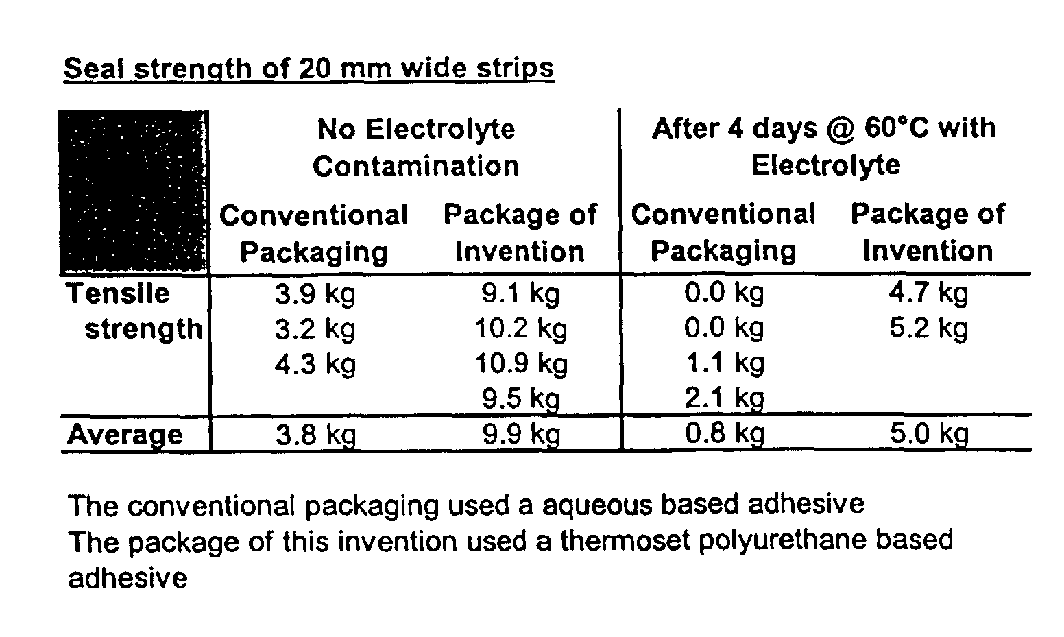
As is apparent, the cell package material of the present invention provides
superior strength as compared to the conventional cell package, both when
contaminated with electrolyte and when uncontaminated.
The Al foil layer should be thick enough to avoid pinholes, preferably in the
range of 25µ to 75µ. In the event that the cell package must be preformed, a formable
grade Al foil should be used.
As noted above, the outer polyester layer 37 is designed to provide mechanical
strength to the cell package 14. It should be understood that the invention is not
limited to the use of polyester for this layer. For example, a laminate of PET and PE
could be used as an alternative.
The methods of the present invention provides the following important
advantages. First, since the cell stack is sealed at the time that the pouch is ruptured,
there is minimal loss of electrolyte. Also, there is no contamination of the equipment.
Further, since the cell package is evacuated prior to the rupturing of the electrolyte
pouch, electrolyte loss is further eliminate as it will not be suctioned from the cell
stack. Further, the only step that must be performed in a glove box (i.e., a dry and
inert atmosphere) is the filling of the pouch with electrolyte and the subsequent
sealing of the pouch. The remaining assembly process steps can be performed in a
dry room. Therefore, the equipment used for manufacturing the cell stack is less
costly. Further, since the vacuum is applied to the package cell under the condition
that the pouch is sealed inside the package, a higher vacuum pressure can be applied
to ensure deep impregnation of the electrolyte into the cell stack without risking loss
of electrolyte.
In addition, the cell package construction with the polypropylene heat sealing
layer and the special adhesive enables the cell package to be heat sealed after the
impregnation of the electrolyte, using the first method described above, and retains its
integrity even when contaminated by electrolyte. Therefore, additional steps
associated with transferring the electrode stack to another, uncontaminated cell
package can be eliminated.
Further, using the tube technique for filling the cell stack with the electrolyte
eliminates altogether the need for heat sealing a contaminated cell package.
The foregoing detailed description is illustrative of the invention, and it is to
be understood that additional embodiments thereof will be obvious to those skilled in
the art. The embodiments disclosed herein together with those additional
embodiments are considered to be within the scope of the invention as described in
the claims appended hereto.
Claims (23)
- A method of fabricating an electrochemical battery, comprising the following steps:forming an electrode cell stack (12) and an enclosure (14);placing said cell stack and a sealed electrolyte pouch (10) together into said enclosure;applying a vacuum to said enclosure;sealing said enclosure; andrupturing said pouch to release said electrolyte (8) into said cell stack.
- The method of fabricating an electrochemical battery according to claim 1, wherein said step of forming said enclosure includes the step of forming a cell package (14).
- The method of fabricating an electrochemical battery according to claim 2, wherein said sealing step includes the step of heat sealing said cell package.
- The method of fabricating an electrochemical battery according to claim 2 or 3, wherein said step of forming said cell package comprises the step of forming first and second parts (31) each comprising a laminate of polyester, aluminum and polypropylene, and wherein said sealing step includes the step of heat sealing said polypropylene layers of said first and second parts to one another.
- The method of fabricating an electrochemical battery according to one of claims 1 to 5, wherein said rupturing step includes the step of squeezing said pouch.
- The method of fabricating an electrochemical battery according to one of claims 1 to 5, wherein said sealing step includes the step of heat sealing said enclosure.
- A method of fabricating an electrochemical battery, comprising the following steps:forming an electrode cell stack (12);injecting an electrolyte (8) into a pouch (10) through an open end;sealing said open end of said pouch in a vacuum state;placing said sealed pouch and said electrode cell stack into an enclosure (14);applying a vacuum to said enclosure; andrupturing said pouch to release said electrolyte into said electrode cell stack
- The method of fabricating an electrochemical battery according to claim 7, wherein said enclosure is a cell package.
- The method of fabricating an electrochemical battery according to claim 7 or 8, wherein said rupturing step includes the step of squeezing said pouch.
- The method of fabricating an electrochemical battery according to claim 7, 8 or 9, wherein said sealing step includes the step of heat sealing said enclosure.
- The method of fabricating an electrochemical battery according to claim 8, 9 or 10, wherein said sealing step includes the step of heat sealing said cell package.
- A method of fabricating an electrochemical battery, comprising the following steps:forming an electrode cell stack (12);placing said cell stack and a sealed electrolyte pouch (10) into a vacuum enclosure (14); andrupturing said pouch to fill said electrode cell stack with electrolyte (8).
- The method of fabricating an electrochemical battery according to claim 12, wherein said sealed electrolyte pouch is a vacuum pouch.
- A method of fabrication an electrochemical battery, comprising the following steps:forming a cell package (14) having first and second enclosures (50, 54) and including a tube (60) communicating between said first and second enclosures;placing a cell stack (12) in said first enclosure with leads of said cell stack protruding from said first enclosure and sealing and evacuating said first enclosure;placing an evacuated electrolyte pouch (10) in said second enclosure and scaling and evacuating said enclosure;rupturing said pouch such that electrolyte flows from said pouch, through said tube and into said cell stack; andsealing said tube.
- The method of claim 14, further comprising the step of removing said second enclosure (54) after said sealing step.
- The method of claim 15, further comprising, after said rupturing step and before said sealing step, the steps of subjecting said cell package to formation and thereafter puncturing said second enclosure and applying a vacuum to said second enclosure to degas said first enclosure.
- A method of fabrication an electrochemical battery, comprising the following steps:forming a cell package (14) having an enclosure (50) and including a tube (60) having one end communicating with said enclosure and an opposite end extending from said cell package;placing a cell stack (12) in said enclosure with leads of said cell stack protruding from said enclosure and sealing and evacuating said first enclosure;introducing electrolyte into said opposite end of said tube such that said electrolyte enters said enclosure and said cell stack; andsealing said tube.
- An electrochemical cell comprising:a casing (14); andan electrode cell stack (12) contained within said casing along with an electrolyte (8), wherein said casing includes first and second parts (31) each comprising a laminate having an outer layer (37), an inner layer (40) and a barrier layer (38) interposed between said inner and outer layers, said first and second parts having their inner layers adhered to one another, said inner layer being a polypropylene layer (40), wherein said inner layer and said barrier layer are adhered together with an adhesive, said adhesive being one of a thermoset polyurethane adhesive or an organosol type modified polypropylene dispersion adhesive.
- The electrochemical cell of claim 18, wherein said outer layer is a polyester layer (37) and said barrier layer is an aluminum layer (38).
- The electrochemical cell of claim 18 or 19, wherein said polypropylene inner layers are heat sealed to each other.
- The electrochemical cell of claim 18, 19 or 20, wherein said first and second parts are unitary with each other.
- The electrochemical cell of claim 18, 19 or 20 wherein said first and second parts are initially independent of each other and are heat sealed to each other around the entire periphery thereof.
- The electrochemical cell of claim 21, 22 or 23, wherein said casing initially includes a first portion (50) in which said cell stack is located and a removable second portion (54) in which an electrolyte pouch is receivable for impregnating said electrodes (12) with said electrolyte (8) upon the bursting of said pouch (10).
Applications Claiming Priority (2)
| Application Number | Priority Date | Filing Date | Title |
|---|---|---|---|
| US291212 | 1994-08-16 | ||
| US09/291,212 US6379838B1 (en) | 1999-04-14 | 1999-04-14 | Cell package |
Publications (1)
| Publication Number | Publication Date |
|---|---|
| EP1045463A1 true EP1045463A1 (en) | 2000-10-18 |
Family
ID=23119362
Family Applications (1)
| Application Number | Title | Priority Date | Filing Date |
|---|---|---|---|
| EP00400648A Withdrawn EP1045463A1 (en) | 1999-04-14 | 2000-03-09 | A method of fabricating an electrochemical cell battery and an improved cell package |
Country Status (3)
| Country | Link |
|---|---|
| US (2) | US6379838B1 (en) |
| EP (1) | EP1045463A1 (en) |
| JP (1) | JP2000306573A (en) |
Cited By (9)
| Publication number | Priority date | Publication date | Assignee | Title |
|---|---|---|---|---|
| WO2002063702A3 (en) * | 2001-02-08 | 2003-12-11 | Eveready Battery Inc | Apparatus and method for assembling a flexible battery that is electrolyte-tight |
| WO2009010720A1 (en) * | 2007-07-17 | 2009-01-22 | Add Power Technologies Limited | Apparatus and method for measuring electrical potential of electrolyte |
| US20130244093A1 (en) * | 2010-12-02 | 2013-09-19 | Lg Chem, Ltd. | Method for manufacturing battery cell and battery cell manufactured using the same |
| GB2504094A (en) * | 2012-07-17 | 2014-01-22 | Energy Control Ltd | Housing Structure for holding a plurality of soft package secondary battery cells |
| WO2014048918A1 (en) | 2012-09-25 | 2014-04-03 | Fraunhofer-Gesellschaft zur Förderung der angewandten Forschung e.V. | Method for filling electrochemical cells |
| CN104868091A (en) * | 2015-05-29 | 2015-08-26 | 芜湖天盛伟业新能源有限公司 | Device for filling liquid into lithium battery |
| CN105723558A (en) * | 2013-11-11 | 2016-06-29 | 日产自动车株式会社 | Manufacturing method of film-encapsulated battery |
| FR3057708A1 (en) * | 2016-10-17 | 2018-04-20 | Commissariat A L'energie Atomique Et Aux Energies Alternatives | PROCESS FOR MANUFACTURING A LITHIUM BAG BATTERY, AND ASSEMBLY COMPRISING A CLOSED BAG COMPRISING ELECTRODES, FOR FILLING WITH A LIQUID ELECTROLYTE |
| CN109358092A (en) * | 2018-10-23 | 2019-02-19 | 国联汽车动力电池研究院有限责任公司 | A kind of packaging effect test method of soft pack battery |
Families Citing this family (31)
| Publication number | Priority date | Publication date | Assignee | Title |
|---|---|---|---|---|
| US6444192B1 (en) * | 1999-02-05 | 2002-09-03 | The Regents Of The University Of California | Diagnostic imaging of lymph structures |
| US7048822B2 (en) * | 1999-12-17 | 2006-05-23 | Dai Nippon Printing Co., Ltd. | Packaging material for polymer cell and method for producing the same |
| US6660430B1 (en) * | 2000-01-24 | 2003-12-09 | Mitsubishi Denki Kabushiki Kaisha | Package for nonaqueous electrolyte cell and cell comprising the same |
| US20040067416A1 (en) * | 2002-10-07 | 2004-04-08 | Maclean Gregory K. | Protective frame for rechargeable battery cells |
| US20050244705A1 (en) * | 2004-04-28 | 2005-11-03 | Jing-Yih Cherng | Electrolyte injection and degas method of electric energy storage device |
| KR100601511B1 (en) | 2004-09-24 | 2006-07-19 | 삼성에스디아이 주식회사 | Lithium Polymer Battery and Manufacturing Method Thereof |
| KR100686807B1 (en) | 2005-03-25 | 2007-02-26 | 삼성에스디아이 주식회사 | Polymer battery packs and manufacturing methods thereof |
| US7682735B2 (en) * | 2005-03-28 | 2010-03-23 | Samsung Sdi Co., Ltd. | Pouch type lithium secondary battery and method of fabricating the same |
| US8852791B2 (en) * | 2005-03-28 | 2014-10-07 | Samsung Sdi Co., Ltd. | Pouch type lithium secondary battery with sleeve and method of fabricating |
| US7920847B2 (en) * | 2005-05-16 | 2011-04-05 | Cisco Technology, Inc. | Method and system to protect the privacy of presence information for network users |
| KR100709881B1 (en) * | 2005-09-28 | 2007-04-20 | 삼성에스디아이 주식회사 | Pouch-type lithium secondary battery and method for manufacturing same |
| CN100411224C (en) * | 2006-10-26 | 2008-08-13 | 丹东金丸集团有限公司 | Adjustable stroke alkaline battery sealing machine |
| JP2009076249A (en) * | 2007-09-19 | 2009-04-09 | Fuji Heavy Ind Ltd | Power storage device |
| US8771866B2 (en) * | 2010-03-30 | 2014-07-08 | Samsung Sdi Co., Ltd. | Pouch type secondary battery and the fabrication method thereof |
| JP5682162B2 (en) * | 2010-07-16 | 2015-03-11 | ソニー株式会社 | Battery manufacturing method |
| EP2477252B1 (en) | 2010-10-04 | 2020-08-19 | LG Chem, Ltd. | Seal tape and secondary battery using the same |
| KR101245284B1 (en) * | 2010-12-20 | 2013-03-19 | 주식회사 엘지화학 | Secondary battery capable of re-injecting electrolyte |
| WO2012162813A1 (en) * | 2011-06-01 | 2012-12-06 | Magna E-Car Systems Limited Partnership | Pouch-type battery cell |
| KR101379691B1 (en) * | 2012-11-19 | 2014-04-01 | 주식회사 엘지화학 | Secondary battery capable of re-injecting electrolyte |
| DE102013201888A1 (en) | 2013-02-06 | 2014-08-07 | Robert Bosch Gmbh | Electrolyte container, battery cell, motor vehicle and method for producing a battery cell |
| US9735402B2 (en) * | 2013-07-30 | 2017-08-15 | Lg Chem, Ltd. | Battery cell having double sealing structure |
| WO2016167116A1 (en) * | 2015-04-16 | 2016-10-20 | Necエナジーデバイス株式会社 | Method and device for manufacturing secondary cell |
| WO2018212121A1 (en) * | 2017-05-18 | 2018-11-22 | 株式会社村田製作所 | Battery semi-fabricated product, battery, battery manufacturing method, battery pack, electronic device, vehicle, power tool, and power storage system |
| JP7334925B2 (en) * | 2019-02-15 | 2023-08-29 | エリーパワー株式会社 | Structural body for lithium ion secondary battery, manufacturing method thereof, package body, and manufacturing method of lithium ion secondary battery |
| EP3926725A4 (en) * | 2019-02-15 | 2023-05-03 | Eliiy Power Co., Ltd. | Structure for nonaqueous electrolyte secondary batteries, method for producing structure for nonaqueous electrolyte secondary batteries, and method for producing nonaqueous electrolyte secondary battery |
| JP7716728B2 (en) * | 2020-02-06 | 2025-08-01 | エリーパワー株式会社 | Structure for non-aqueous electrolyte secondary battery, method for manufacturing the same, and method for manufacturing non-aqueous electrolyte secondary battery |
| US11742525B2 (en) | 2020-02-07 | 2023-08-29 | 24M Technologies, Inc. | Divided energy electrochemical cell systems and methods of producing the same |
| US12381277B2 (en) | 2020-06-17 | 2025-08-05 | 24M Technologies, Inc. | Electrochemical cells with flame retardant mechanism and methods of producing the same |
| US12246903B2 (en) | 2020-11-02 | 2025-03-11 | Medtronic, Inc. | Foil pack |
| CN113851794B (en) * | 2021-08-12 | 2023-09-05 | 惠州锂威新能源科技有限公司 | Battery liquid injection method and application thereof |
| CN115020937A (en) * | 2022-06-08 | 2022-09-06 | 捷威动力工业嘉兴有限公司 | Soft-packaged electrical core secondary fluid infusion encapsulation complementary unit |
Citations (9)
| Publication number | Priority date | Publication date | Assignee | Title |
|---|---|---|---|---|
| US3865631A (en) * | 1973-12-26 | 1975-02-11 | Charles S Naiman | Reserve batteries |
| JPS61171061A (en) * | 1985-01-24 | 1986-08-01 | Japan Storage Battery Co Ltd | Method of pouring electrolyte into cylindrical battery after it is evacuated |
| JPS6348778A (en) * | 1986-08-19 | 1988-03-01 | Bridgestone Corp | Manufacture of cell |
| JPS6386273A (en) * | 1986-09-27 | 1988-04-16 | Japan Storage Battery Co Ltd | Manufacture of sealed lead acid battery |
| JPH0286057A (en) * | 1988-09-21 | 1990-03-27 | Japan Storage Battery Co Ltd | Electrolyte pouring method for reserve battery |
| EP0397248A2 (en) * | 1989-05-08 | 1990-11-14 | Eastman Kodak Company | Electrochemical cell modules |
| EP0845821A2 (en) * | 1996-11-28 | 1998-06-03 | SANYO ELECTRIC Co., Ltd. | Thin type battery with laminated sheathing |
| JPH10208778A (en) * | 1997-01-22 | 1998-08-07 | Sumitomo Electric Ind Ltd | Non-aqueous electrolyte battery |
| WO1998042036A1 (en) * | 1997-03-19 | 1998-09-24 | Asahi Kasei Kogyo Kabushiki Kaisha | Nonaqueous thin battery |
Family Cites Families (19)
| Publication number | Priority date | Publication date | Assignee | Title |
|---|---|---|---|---|
| US4031296A (en) | 1973-05-10 | 1977-06-21 | John C. Bogue | Electrochemical energy cell |
| US3990917A (en) | 1973-12-26 | 1976-11-09 | Charles S. Naiman | Reserve batteries |
| US4326015A (en) | 1978-10-23 | 1982-04-20 | The United States Of America As Represented By The Secretary Of The Navy | Battery activate assembly |
| SE450742B (en) | 1982-12-30 | 1987-07-20 | Philips Norden Ab | ACTIVABLE BATTERY |
| US4588662A (en) | 1985-07-29 | 1986-05-13 | The United States Of America As Represented By The Secretary Of The Navy | Method and device for filling the cells of a battery with electrolyte |
| US4628014A (en) | 1986-01-28 | 1986-12-09 | Ultimate Survivor Of America Inc. | Deferred-action battery |
| US4999263A (en) | 1987-04-15 | 1991-03-12 | Ricoh Company, Ltd. | Sheet-shaped electrode, method or producing the same, and secondary battery |
| US4800141A (en) | 1987-11-17 | 1989-01-24 | Honeywell Inc. | Reserve activated electrochemical cell |
| US4861686A (en) | 1988-02-03 | 1989-08-29 | Motorola, Inc. | Multi-cell, vacuum activated deferred action battery |
| US4803135A (en) | 1988-02-29 | 1989-02-07 | Honeywell Inc. | Pressure Activated reserve battery |
| CA2011720C (en) | 1989-03-30 | 1999-11-30 | Robert A. Austin | Battery in a vacuum sealed enveloping material and a process for making the same |
| US4997732A (en) | 1989-03-30 | 1991-03-05 | Mhb Joint Venture | Battery in a vacuum sealed enveloping material and a process for making the same |
| US4968567A (en) | 1989-07-31 | 1990-11-06 | Honeywell Inc. | Reserve activated electrochemical cell with a cell condition checking apparatus |
| US5201924A (en) | 1991-09-03 | 1993-04-13 | General Motors Corporation | Filling mat-immobilized-electrolyte batteries |
| JP3397351B2 (en) | 1992-12-18 | 2003-04-14 | キヤノン株式会社 | Prismatic or sheet type battery and manufacturing method thereof |
| JPH0785847A (en) | 1993-09-17 | 1995-03-31 | Matsushita Electric Ind Co Ltd | Sealed alkaline storage battery unit cell and battery system |
| US5695530A (en) | 1994-03-14 | 1997-12-09 | Hong; Kuochih | Method for making high charging efficiency and fast oxygen recombination rechargeable hydride batteries |
| EP0693792B1 (en) | 1994-07-19 | 2003-01-08 | Canon Kabushiki Kaisha | Rechargeable batteries having a specific anode and process for the production of them |
| US5512160A (en) | 1995-08-10 | 1996-04-30 | Hughes Aircraft Company | Nickel-cadmium battery activation process |
-
1999
- 1999-04-14 US US09/291,212 patent/US6379838B1/en not_active Expired - Fee Related
-
2000
- 2000-03-01 JP JP2000055247A patent/JP2000306573A/en active Pending
- 2000-03-09 EP EP00400648A patent/EP1045463A1/en not_active Withdrawn
-
2001
- 2001-09-10 US US09/949,079 patent/US20020022180A1/en not_active Abandoned
Patent Citations (10)
| Publication number | Priority date | Publication date | Assignee | Title |
|---|---|---|---|---|
| US3865631A (en) * | 1973-12-26 | 1975-02-11 | Charles S Naiman | Reserve batteries |
| JPS61171061A (en) * | 1985-01-24 | 1986-08-01 | Japan Storage Battery Co Ltd | Method of pouring electrolyte into cylindrical battery after it is evacuated |
| JPS6348778A (en) * | 1986-08-19 | 1988-03-01 | Bridgestone Corp | Manufacture of cell |
| JPS6386273A (en) * | 1986-09-27 | 1988-04-16 | Japan Storage Battery Co Ltd | Manufacture of sealed lead acid battery |
| JPH0286057A (en) * | 1988-09-21 | 1990-03-27 | Japan Storage Battery Co Ltd | Electrolyte pouring method for reserve battery |
| EP0397248A2 (en) * | 1989-05-08 | 1990-11-14 | Eastman Kodak Company | Electrochemical cell modules |
| EP0845821A2 (en) * | 1996-11-28 | 1998-06-03 | SANYO ELECTRIC Co., Ltd. | Thin type battery with laminated sheathing |
| JPH10208778A (en) * | 1997-01-22 | 1998-08-07 | Sumitomo Electric Ind Ltd | Non-aqueous electrolyte battery |
| WO1998042036A1 (en) * | 1997-03-19 | 1998-09-24 | Asahi Kasei Kogyo Kabushiki Kaisha | Nonaqueous thin battery |
| EP0973212A1 (en) * | 1997-03-19 | 2000-01-19 | Asahi Kasei Kogyo Kabushiki Kaisha | Nonaqueous thin battery |
Non-Patent Citations (5)
| Title |
|---|
| PATENT ABSTRACTS OF JAPAN vol. 010, no. 379 (E - 465) 18 December 1986 (1986-12-18) * |
| PATENT ABSTRACTS OF JAPAN vol. 012, no. 265 (E - 637) 23 July 1988 (1988-07-23) * |
| PATENT ABSTRACTS OF JAPAN vol. 012, no. 320 (E - 651) 30 August 1988 (1988-08-30) * |
| PATENT ABSTRACTS OF JAPAN vol. 014, no. 273 (E - 0940) 13 June 1990 (1990-06-13) * |
| PATENT ABSTRACTS OF JAPAN vol. 1998, no. 13 30 November 1998 (1998-11-30) * |
Cited By (20)
| Publication number | Priority date | Publication date | Assignee | Title |
|---|---|---|---|---|
| US6676714B2 (en) | 2001-02-08 | 2004-01-13 | Eveready Battery Company, Inc. | Apparatus and method for assembling a flexible battery that is electrolyte-tight |
| WO2002063702A3 (en) * | 2001-02-08 | 2003-12-11 | Eveready Battery Inc | Apparatus and method for assembling a flexible battery that is electrolyte-tight |
| WO2009010720A1 (en) * | 2007-07-17 | 2009-01-22 | Add Power Technologies Limited | Apparatus and method for measuring electrical potential of electrolyte |
| US8974955B2 (en) * | 2010-12-02 | 2015-03-10 | Lg Chem, Ltd. | Method for manufacturing battery cell and battery cell manufactured using the same |
| US20130244093A1 (en) * | 2010-12-02 | 2013-09-19 | Lg Chem, Ltd. | Method for manufacturing battery cell and battery cell manufactured using the same |
| GB2504094A (en) * | 2012-07-17 | 2014-01-22 | Energy Control Ltd | Housing Structure for holding a plurality of soft package secondary battery cells |
| US9431648B2 (en) | 2012-09-25 | 2016-08-30 | Fraunhoder-Gesellschaft zur Foerderung der angewandten Forschung e.V. | Method for filling electrochemical cells |
| CN104704650B (en) * | 2012-09-25 | 2017-09-15 | 弗兰霍菲尔运输应用研究公司 | Method for filling electrochemical cells |
| DE102012109032B4 (en) * | 2012-09-25 | 2019-11-28 | Fraunhofer-Gesellschaft zur Förderung der angewandten Forschung e.V. | Method for filling electrochemical cells |
| DE102012109032A1 (en) * | 2012-09-25 | 2014-05-28 | Fraunhofer-Gesellschaft zur Förderung der angewandten Forschung e.V. | Method for filling electrochemical cells |
| WO2014048918A1 (en) | 2012-09-25 | 2014-04-03 | Fraunhofer-Gesellschaft zur Förderung der angewandten Forschung e.V. | Method for filling electrochemical cells |
| US9847556B2 (en) | 2013-11-11 | 2017-12-19 | Nissan Motor Co., Ltd. | Method for manufacturing film-packaged cell |
| EP3070779A4 (en) * | 2013-11-11 | 2016-09-28 | Nissan Motor | PROCESS FOR MANUFACTURING PACKAGED PACKAGED UNDER FILM |
| CN105723558A (en) * | 2013-11-11 | 2016-06-29 | 日产自动车株式会社 | Manufacturing method of film-encapsulated battery |
| CN105723558B (en) * | 2013-11-11 | 2019-04-09 | 日产自动车株式会社 | Manufacturing method of thin film encapsulated battery |
| CN104868091B (en) * | 2015-05-29 | 2018-05-25 | 芜湖天盛伟业新能源有限公司 | A kind of device for lithium battery fluid injection |
| CN104868091A (en) * | 2015-05-29 | 2015-08-26 | 芜湖天盛伟业新能源有限公司 | Device for filling liquid into lithium battery |
| FR3057708A1 (en) * | 2016-10-17 | 2018-04-20 | Commissariat A L'energie Atomique Et Aux Energies Alternatives | PROCESS FOR MANUFACTURING A LITHIUM BAG BATTERY, AND ASSEMBLY COMPRISING A CLOSED BAG COMPRISING ELECTRODES, FOR FILLING WITH A LIQUID ELECTROLYTE |
| CN109358092A (en) * | 2018-10-23 | 2019-02-19 | 国联汽车动力电池研究院有限责任公司 | A kind of packaging effect test method of soft pack battery |
| CN109358092B (en) * | 2018-10-23 | 2021-11-09 | 国联汽车动力电池研究院有限责任公司 | Method for testing packaging effect of soft package battery |
Also Published As
| Publication number | Publication date |
|---|---|
| US20020022180A1 (en) | 2002-02-21 |
| JP2000306573A (en) | 2000-11-02 |
| US6379838B1 (en) | 2002-04-30 |
Similar Documents
| Publication | Publication Date | Title |
|---|---|---|
| US6379838B1 (en) | Cell package | |
| EP1396037B1 (en) | Apparatus and method for assembling a flexible battery that is electrolyte-tight | |
| JP5010467B2 (en) | Film-clad electrical device and method for manufacturing the same | |
| US6582480B2 (en) | Method of fabricating electrochemical cell | |
| EP1050082B1 (en) | Battery terminal insulation | |
| EP2860809B1 (en) | Manufacturing method and manufacturing device of secondary battery | |
| EP2237345A1 (en) | Sealed type cell manufacturing method | |
| US20020164441A1 (en) | Packaging for primary and secondary batteries | |
| EP2012376A1 (en) | Sealing structure in a secondary battery | |
| US20030082445A1 (en) | Battery pouch | |
| KR102120496B1 (en) | Oxygen permeable membrane for air secondary battery, armouring material for air secondary battery and secondary battery | |
| KR102900629B1 (en) | Method for formationing battery cell and method for manufacturing battery cell including the same | |
| JP2026511486A (en) | secondary battery | |
| JP2003508906A (en) | Charge storage device | |
| JP5687782B1 (en) | Metal air battery | |
| KR100358867B1 (en) | Laminated film, its manufacturing method and bag and package using laminated film | |
| EP4411906A1 (en) | Method for manufacturing a battery cell with a pouch housing | |
| DE69929674T2 (en) | SHEET FOR CELL HOUSING AND CELL ARRANGEMENT | |
| US7129002B2 (en) | Method for producing a rechargeable electrochemical element | |
| JP7437740B2 (en) | Structure for non-aqueous electrolyte secondary battery, manufacturing device for non-aqueous electrolyte secondary battery, and manufacturing method for non-aqueous electrolyte secondary battery | |
| US20260038986A1 (en) | Battery cell manufacturing method and battery cell | |
| HK1061925B (en) | Apparatus and method for assembling a flexible battery that is electrolyte-tight | |
| KR20260045630A (en) | Secondary battery and manufacturing method of secondary battery | |
| KR20180065947A (en) | Method for making pouch-typed secondary batteries controlling discharge of electrolyte solution and apparatus therefor | |
| JP2000355335A (en) | Pouch having easily pierceable part and sheet material therefor |
Legal Events
| Date | Code | Title | Description |
|---|---|---|---|
| PUAI | Public reference made under article 153(3) epc to a published international application that has entered the european phase |
Free format text: ORIGINAL CODE: 0009012 |
|
| AK | Designated contracting states |
Kind code of ref document: A1 Designated state(s): DE FR GB |
|
| AX | Request for extension of the european patent |
Free format text: AL;LT;LV;MK;RO;SI |
|
| 17P | Request for examination filed |
Effective date: 20010330 |
|
| AKX | Designation fees paid |
Free format text: DE FR GB |
|
| 17Q | First examination report despatched |
Effective date: 20040802 |
|
| STAA | Information on the status of an ep patent application or granted ep patent |
Free format text: STATUS: THE APPLICATION IS DEEMED TO BE WITHDRAWN |
|
| 18D | Application deemed to be withdrawn |
Effective date: 20041001 |