EP2477252B1 - Seal tape and secondary battery using the same - Google Patents
Seal tape and secondary battery using the same Download PDFInfo
- Publication number
- EP2477252B1 EP2477252B1 EP10852643.5A EP10852643A EP2477252B1 EP 2477252 B1 EP2477252 B1 EP 2477252B1 EP 10852643 A EP10852643 A EP 10852643A EP 2477252 B1 EP2477252 B1 EP 2477252B1
- Authority
- EP
- European Patent Office
- Prior art keywords
- adhesive layer
- electrode assembly
- seal tape
- adhesive
- secondary battery
- Prior art date
- Legal status (The legal status is an assumption and is not a legal conclusion. Google has not performed a legal analysis and makes no representation as to the accuracy of the status listed.)
- Active
Links
- 239000012790 adhesive layer Substances 0.000 claims description 169
- 239000003792 electrolyte Substances 0.000 claims description 79
- 230000001070 adhesive effect Effects 0.000 claims description 73
- 239000011241 protective layer Substances 0.000 claims description 49
- 239000000853 adhesive Substances 0.000 claims description 38
- 239000000463 material Substances 0.000 claims description 25
- 239000010410 layer Substances 0.000 claims description 17
- 239000000758 substrate Substances 0.000 claims description 15
- 229920000058 polyacrylate Polymers 0.000 claims description 2
- 239000004798 oriented polystyrene Substances 0.000 description 28
- IEJIGPNLZYLLBP-UHFFFAOYSA-N dimethyl carbonate Chemical compound COC(=O)OC IEJIGPNLZYLLBP-UHFFFAOYSA-N 0.000 description 9
- 238000004519 manufacturing process Methods 0.000 description 8
- 235000015110 jellies Nutrition 0.000 description 7
- 239000008274 jelly Substances 0.000 description 7
- 238000000034 method Methods 0.000 description 6
- 238000005096 rolling process Methods 0.000 description 6
- 230000008961 swelling Effects 0.000 description 5
- WHXSMMKQMYFTQS-UHFFFAOYSA-N Lithium Chemical compound [Li] WHXSMMKQMYFTQS-UHFFFAOYSA-N 0.000 description 4
- 229910052744 lithium Inorganic materials 0.000 description 4
- YXFVVABEGXRONW-UHFFFAOYSA-N Toluene Chemical compound CC1=CC=CC=C1 YXFVVABEGXRONW-UHFFFAOYSA-N 0.000 description 3
- 239000002390 adhesive tape Substances 0.000 description 3
- 230000008878 coupling Effects 0.000 description 3
- 238000010168 coupling process Methods 0.000 description 3
- 238000005859 coupling reaction Methods 0.000 description 3
- 238000005520 cutting process Methods 0.000 description 3
- 238000004880 explosion Methods 0.000 description 3
- 238000010304 firing Methods 0.000 description 3
- 229910052751 metal Inorganic materials 0.000 description 3
- 239000002184 metal Substances 0.000 description 3
- 239000002861 polymer material Substances 0.000 description 3
- 238000007669 thermal treatment Methods 0.000 description 3
- HBBGRARXTFLTSG-UHFFFAOYSA-N Lithium ion Chemical compound [Li+] HBBGRARXTFLTSG-UHFFFAOYSA-N 0.000 description 2
- PXHVJJICTQNCMI-UHFFFAOYSA-N Nickel Chemical compound [Ni] PXHVJJICTQNCMI-UHFFFAOYSA-N 0.000 description 2
- 239000006183 anode active material Substances 0.000 description 2
- 239000006182 cathode active material Substances 0.000 description 2
- 239000007788 liquid Substances 0.000 description 2
- 229910001416 lithium ion Inorganic materials 0.000 description 2
- 229920001490 poly(butyl methacrylate) polymer Polymers 0.000 description 2
- 229920001483 poly(ethyl methacrylate) polymer Polymers 0.000 description 2
- 229920003229 poly(methyl methacrylate) Polymers 0.000 description 2
- 229920000642 polymer Polymers 0.000 description 2
- 239000004926 polymethyl methacrylate Substances 0.000 description 2
- -1 polypropylene Polymers 0.000 description 2
- 239000007787 solid Substances 0.000 description 2
- 229920001187 thermosetting polymer Polymers 0.000 description 2
- SOGAXMICEFXMKE-UHFFFAOYSA-N Butylmethacrylate Chemical compound CCCCOC(=O)C(C)=C SOGAXMICEFXMKE-UHFFFAOYSA-N 0.000 description 1
- UFHFLCQGNIYNRP-UHFFFAOYSA-N Hydrogen Chemical compound [H][H] UFHFLCQGNIYNRP-UHFFFAOYSA-N 0.000 description 1
- CTQNGGLPUBDAKN-UHFFFAOYSA-N O-Xylene Chemical compound CC1=CC=CC=C1C CTQNGGLPUBDAKN-UHFFFAOYSA-N 0.000 description 1
- 239000004698 Polyethylene Substances 0.000 description 1
- 239000004642 Polyimide Substances 0.000 description 1
- 239000004743 Polypropylene Substances 0.000 description 1
- 229910052782 aluminium Inorganic materials 0.000 description 1
- XAGFODPZIPBFFR-UHFFFAOYSA-N aluminium Chemical compound [Al] XAGFODPZIPBFFR-UHFFFAOYSA-N 0.000 description 1
- OJIJEKBXJYRIBZ-UHFFFAOYSA-N cadmium nickel Chemical compound [Ni].[Cd] OJIJEKBXJYRIBZ-UHFFFAOYSA-N 0.000 description 1
- 239000003575 carbonaceous material Substances 0.000 description 1
- 230000001413 cellular effect Effects 0.000 description 1
- 238000006243 chemical reaction Methods 0.000 description 1
- 230000000694 effects Effects 0.000 description 1
- 229910052739 hydrogen Inorganic materials 0.000 description 1
- 239000001257 hydrogen Substances 0.000 description 1
- 238000003780 insertion Methods 0.000 description 1
- 230000037431 insertion Effects 0.000 description 1
- FUJCRWPEOMXPAD-UHFFFAOYSA-N lithium oxide Chemical compound [Li+].[Li+].[O-2] FUJCRWPEOMXPAD-UHFFFAOYSA-N 0.000 description 1
- 229910001947 lithium oxide Inorganic materials 0.000 description 1
- 229910052759 nickel Inorganic materials 0.000 description 1
- 239000012454 non-polar solvent Substances 0.000 description 1
- 229920000573 polyethylene Polymers 0.000 description 1
- 229920001721 polyimide Polymers 0.000 description 1
- 229920001155 polypropylene Polymers 0.000 description 1
- 239000011148 porous material Substances 0.000 description 1
- 238000007789 sealing Methods 0.000 description 1
- 239000002356 single layer Substances 0.000 description 1
- 239000002904 solvent Substances 0.000 description 1
- 238000003860 storage Methods 0.000 description 1
- 238000003466 welding Methods 0.000 description 1
- 239000008096 xylene Substances 0.000 description 1
Images


Classifications
-
- H—ELECTRICITY
- H01—ELECTRIC ELEMENTS
- H01M—PROCESSES OR MEANS, e.g. BATTERIES, FOR THE DIRECT CONVERSION OF CHEMICAL ENERGY INTO ELECTRICAL ENERGY
- H01M50/00—Constructional details or processes of manufacture of the non-active parts of electrochemical cells other than fuel cells, e.g. hybrid cells
- H01M50/10—Primary casings, jackets or wrappings of a single cell or a single battery
- H01M50/183—Sealing members
-
- H—ELECTRICITY
- H01—ELECTRIC ELEMENTS
- H01M—PROCESSES OR MEANS, e.g. BATTERIES, FOR THE DIRECT CONVERSION OF CHEMICAL ENERGY INTO ELECTRICAL ENERGY
- H01M10/00—Secondary cells; Manufacture thereof
- H01M10/04—Construction or manufacture in general
- H01M10/0413—Large-sized flat cells or batteries for motive or stationary systems with plate-like electrodes
-
- H—ELECTRICITY
- H01—ELECTRIC ELEMENTS
- H01M—PROCESSES OR MEANS, e.g. BATTERIES, FOR THE DIRECT CONVERSION OF CHEMICAL ENERGY INTO ELECTRICAL ENERGY
- H01M10/00—Secondary cells; Manufacture thereof
- H01M10/04—Construction or manufacture in general
- H01M10/0431—Cells with wound or folded electrodes
-
- H—ELECTRICITY
- H01—ELECTRIC ELEMENTS
- H01M—PROCESSES OR MEANS, e.g. BATTERIES, FOR THE DIRECT CONVERSION OF CHEMICAL ENERGY INTO ELECTRICAL ENERGY
- H01M10/00—Secondary cells; Manufacture thereof
- H01M10/04—Construction or manufacture in general
- H01M10/0436—Small-sized flat cells or batteries for portable equipment
-
- H—ELECTRICITY
- H01—ELECTRIC ELEMENTS
- H01M—PROCESSES OR MEANS, e.g. BATTERIES, FOR THE DIRECT CONVERSION OF CHEMICAL ENERGY INTO ELECTRICAL ENERGY
- H01M10/00—Secondary cells; Manufacture thereof
- H01M10/04—Construction or manufacture in general
- H01M10/0468—Compression means for stacks of electrodes and separators
-
- H—ELECTRICITY
- H01—ELECTRIC ELEMENTS
- H01M—PROCESSES OR MEANS, e.g. BATTERIES, FOR THE DIRECT CONVERSION OF CHEMICAL ENERGY INTO ELECTRICAL ENERGY
- H01M50/00—Constructional details or processes of manufacture of the non-active parts of electrochemical cells other than fuel cells, e.g. hybrid cells
- H01M50/10—Primary casings, jackets or wrappings of a single cell or a single battery
- H01M50/183—Sealing members
- H01M50/19—Sealing members characterised by the material
- H01M50/193—Organic material
-
- Y—GENERAL TAGGING OF NEW TECHNOLOGICAL DEVELOPMENTS; GENERAL TAGGING OF CROSS-SECTIONAL TECHNOLOGIES SPANNING OVER SEVERAL SECTIONS OF THE IPC; TECHNICAL SUBJECTS COVERED BY FORMER USPC CROSS-REFERENCE ART COLLECTIONS [XRACs] AND DIGESTS
- Y02—TECHNOLOGIES OR APPLICATIONS FOR MITIGATION OR ADAPTATION AGAINST CLIMATE CHANGE
- Y02E—REDUCTION OF GREENHOUSE GAS [GHG] EMISSIONS, RELATED TO ENERGY GENERATION, TRANSMISSION OR DISTRIBUTION
- Y02E60/00—Enabling technologies; Technologies with a potential or indirect contribution to GHG emissions mitigation
- Y02E60/10—Energy storage using batteries
-
- Y—GENERAL TAGGING OF NEW TECHNOLOGICAL DEVELOPMENTS; GENERAL TAGGING OF CROSS-SECTIONAL TECHNOLOGIES SPANNING OVER SEVERAL SECTIONS OF THE IPC; TECHNICAL SUBJECTS COVERED BY FORMER USPC CROSS-REFERENCE ART COLLECTIONS [XRACs] AND DIGESTS
- Y02—TECHNOLOGIES OR APPLICATIONS FOR MITIGATION OR ADAPTATION AGAINST CLIMATE CHANGE
- Y02P—CLIMATE CHANGE MITIGATION TECHNOLOGIES IN THE PRODUCTION OR PROCESSING OF GOODS
- Y02P70/00—Climate change mitigation technologies in the production process for final industrial or consumer products
- Y02P70/50—Manufacturing or production processes characterised by the final manufactured product
Definitions
- the present disclosure relates to a secondary battery and a seal tape used for the same, and more particularly, to a seal tape attached to the outer surface of an electrode assembly to prevent the electrode assembly from being released or moved.
- a secondary battery refers to a rechargeable battery
- a general battery refers to a non-rechargeable battery.
- Secondary batteries are widely used for electronic devices such as cellular phones, notebook computers, video cameras, electric vehicles, or the like.
- a lithium secondary battery has an operating voltage of about 3.6 V, triple the capacity of nickel-cadmium batteries or nickel hydrogen batteries generally used as power sources of electronic devices, and due to its high energy density per unit weight, are being utilized more and more.
- the lithium secondary battery generally uses lithium oxide and carbonaceous material as cathode active material and anode active material, respectively.
- the lithium secondary battery includes an electrode assembly in which a cathode plate and an anode plate respectively coated with the cathode active material and the anode active material are disposed with a separator being interposed between them, and an exterior material which seals and receives the electrode assembly together with an electrolyte.
- the lithium secondary battery may be classified into a can type secondary battery where the electrode assembly is included in a metal can and a pouch type battery where the electrode assembly is included in a pouch of an aluminum laminate depending on the shape of the battery case.
- the can type secondary battery may further be classified into a cylindrical battery and a rectangular battery depending on the shape of the metal can.
- the electrode assembly is classified into a jelly roll type electrode assembly where a separator is interposed between the cathode plate and the anode plate and then rolled, and a stack type electrode assembly where separators are interposed between a plurality of cathode plates and anode plates with a predetermined size and then successively laminated.
- the stack type electrode assembly is generally used for a pouch type battery
- the jelly roll type electrode assembly is generally used for a can type secondary battery.
- the jelly roll type electrode assembly is widely used due to its advantages such as easy fabrication, high energy density per weight, and easy storage in a cylindrical or rectangular battery can.
- the cathode plate, the anode plate and the separator are laminated and rolled.
- a seal tape is attached to the outermost terminal or a rolling end of the electrode assembly, so that the electrode assembly may maintain its rolled state without being released.
- the electrode assembly to which the seal tape is attached as described above is received in a metal can together with an electrolyte, and a cap assembly having an electrode terminal is coupled to the upper opening end of the battery case.
- the secondary battery having the above configuration has a problem in that the electrode assembly may move vertically or horizontally in the battery if the battery falls or external impact is applied thereto. Such movement of the electrode assembly may cut a tap connected between the electrode assembly and the cap assembly, which may cause a power insensitive phenomenon of the secondary battery.
- the vertical movement of the electrode assembly presses the upper or lower portion of the electrode assembly to deform the electrode assembly and cause a short circuit, which may break the secondary battery and lead to accidents such as firing or explosion, causing great damage.
- the vertical movement of the electrode assembly may give impact to the cap assembly coupled to the upper opening portion of the secondary battery, causing the sealing portion to break or separate, which may lead to the electrolyte in the secondary battery to leak.
- EP 2 273 601 A1 relates to a secondary battery which includes i) an electrode assembly, ii) an electrolyte, iii) a tape attached to at least part of an outer surface of the electrode assembly and iv) a case accommodating the electrode assembly, electrolyte and tape.
- EP 1 804 320 A2 relates to an electrode assembly for a lithium ion secondary battery and a lithium ion secondary battery using the same.
- the present disclosure is designed to solve the problems of the prior art, and therefore it is an object of the present disclosure to provide a seal tape capable of preventing an electrode assembly from moving in a secondary battery, and a secondary battery using the same.
- seal tape for a secondary battery as in claim 1, which is attached to an outer surface of an electrode assembly, which is received in a battery case, the seal tape including: a first adhesive layer having an adhesive surface adhered to the outer surface of the electrode assembly; and a second adhesive layer having an adhesive surface at a side opposite to the adhesive surface of the first adhesive layer so as to adhere to an inner surface of the battery case.
- the second adhesive layer exhibits an adhesive property by reacting with an electrolyte of the secondary battery.
- the seal tape further includes a protective layer formed on the second adhesive layer, wherein the protective layer is partially removed by reacting with an electrolyte of the secondary battery.
- a secondary battery as defined in the attached set of claims, which includes: an electrode assembly including a cathode plate and an anode plate disposed with a separator being interposed between them; a battery case receiving the electrode assembly and an electrolyte; and a seal tape having a first adhesive layer adhered to an outer surface of the electrode assembly and a second adhesive layer with an adhesive surface formed at a side opposite to the adhesive surface of the first adhesive layer so as to adhere to an inner surface of the battery case.
- the second adhesive layer exhibits an adhesive property by reacting with the electrolyte.
- the seal tape further includes a protective layer formed on the second adhesive layer and is partially removed by reacting with the electrolyte.
- the present disclosure it is possible to prevent the electrode assembly in a rolled state from being released in the secondary battery and to prevent the electrode assembly from moving in the battery case.
- the seal tape when the seal tape is impregnated with the electrolyte in the secondary battery, the seal tape swells.
- the swelling seal tape may play a role of absorbing the impact transferred from the outside of the secondary battery to the electrode assembly. Therefore, the electrode assembly may be more stably protected.
- the breaking of the coupling portion between the cap assembly and the battery case can be prevented. Therefore, it is possible to prevent the electrolyte from leaking caused by the damage of the coupling portion of the cap assembly.
- Fig. 1 is a partial cross-sectional view schematically showing a seal tape 100 for a secondary battery according to an embodiment of the present disclosure.
- the seal tape 100 for a secondary battery includes a first adhesive layer 110 and a second adhesive layer 120.
- the first adhesive layer 110 is a layer formed on one surface of the seal tape 100 so that it may adhere to the outer surface of an electrode assembly. In a case where the seal tape 100 is attached to an electrode assembly, the adhesive surface of the first adhesive layer 110 directly adheres to the outer circumference of the electrode assembly.
- the first adhesive layer 110 is made of adhesive material generally used in seal tapes of a secondary battery, or various kinds of other adhesive material may also be used.
- the first adhesive layer 110 adhered to the electrode assembly is well known in the art and not described here in detail.
- the present disclosure is not limited to the material or manufacturing method of the first adhesive layer 110, and various kinds of adhesive materials known in the art at the filing of this application may be used as the material of the first adhesive layer 110.
- the second adhesive layer 120 is an adhesive layer having an adhesive surface at a surface opposite to the adhesive surface of the first adhesive layer 110. Due to the second adhesive layer 120, the seal tape 100 for a secondary battery according to the present disclosure is formed to have adhesive layers on both surfaces, different from a general seal tape for a secondary battery which has an adhesive layer on only one surface.
- the second adhesive layer 120 is configured so that its adhesive surface directly contacts and adheres to the inner surface of the battery case in a case where the electrode assembly is received in the battery case.
- the second adhesive layer 120 may be made of the same adhesive material as the first adhesive layer 110. Therefore, even though the figures of the first adhesive layer 110 and the second adhesive layer 120 distinguishably are configured to illustrate the separate layers for the sake of convenience, in a case where the second adhesive layer 120 and the first adhesive layer 110 are made of the same adhesive material, they may be in the form of a indistinguishable single adhesive layer.
- the second adhesive layer 120 may be made of adhesive material different from the first adhesive layer 110.
- the second adhesive layer 120 exhibits an adhesive property by reacting with the secondary battery.
- the second adhesive layer 120 of the seal tape 100 does not have an adhesive property before it reacts with the electrolyte, but preferably has an adhesive property after it reacts with the electrolyte.
- the adhesive property of the second adhesive layer 120 is not exhibited, and the adhesive property of the second adhesive layer 120 is exhibited only after the electrode assembly is inserted into the battery case and the electrolyte is injected thereto. Therefore, the electrode assembly to which the seal tape 100 is attached may be easily inserted into the battery case.
- the second adhesive layer 120 is made of oriented polystyrene (OPS).
- OPS oriented polystyrene
- the second adhesive layer 120 may be an OPS film.
- the second adhesive layer 120 namely the OPS film, does not have an adhesive property, but it may have an adhesive property when reacting with a certain component of the electrolyte, for example dimethyl carbonate (DMC).
- DMC dimethyl carbonate
- the OPS film is a solid film and generally does not have an adhesive property. However, if the OPS film reacts with the DMC, the DMC penetrates the pores of the polymer chains so that the polymer chains changes to a movable state allowing easy movement and has an adhesive property.
- the OPS film reacts with the DMC to shift its phase from a solid state to a viscous liquid state, which gives an adhesive property. Therefore, in a case where an electrolyte is injected into the battery case, in which the electrode assembly to which the seal tape 100 is attached is inserted, the adhesive property of the OPS film is exhibited, which allows the adhesion with the inner surface of the battery case.
- the OPS film which has reacted with the electrolyte to shift its phase into a viscous liquid state as described above, may start a shrinking reaction by thermal treatment of about 60°C and become slowly solidified while losing the solvent component little by little. Therefore, in a case where the second adhesive layer 120 is made of an OPS film like the above embodiment, the OPS film may be solidified again by performing a thermal treatment process, a predetermined time after the electrolyte is injected into the battery case. At this time, the thermal treatment process may be a process included in an existing secondary battery manufacturing process or an additional separate process.
- the component of the electrolyte reacting with the OPS film to exhibit an adhesive property of the OPS film is the DMC, it is merely just an example, and the OPS film may exhibit its adhesive property by means of other nonpolar solvents such as toluene and xylene.
- the first adhesive layer 110 may substantially have a thickness of 7 ⁇ m
- the second adhesive layer 120 may substantially have a thickness of 40 ⁇ m.
- the thicknesses of the first adhesive layer 110 and the second adhesive layer 120 are just an example, and the present disclosure is not limited to such specific thicknesses of the first adhesive layer 110 and the second adhesive layer 120.
- the thickness of the entire seal tape 100, or the thickness of the first adhesive layer 110 or the second adhesive layer 120 may be suitably determined according to various factors such as the kinds of the first adhesive layer 110 and the second adhesive layer 120, the size or rolling shape of the electrode assembly, the kind of electrolyte, the size and capacity of the battery case, the size or manufacturing process of the secondary battery, or the like.
- the second adhesive layer 120 may be made of thermosetting adhesive material which exhibits an adhesive property when heat more than a predetermined level is applied.
- the adhesive property of the second adhesive layer 120 is not exhibited so that the electrode assembly may be inserted into the battery case without any disturbance from the second adhesive layer 120.
- heat more than the predetermined level is applied to the seal tape 100 so that the second adhesive layer 120 exhibits an adhesive property, which allows the second adhesive layer 120 to adhere to the inner surface of the battery case.
- the heat applying process as described above may be included in an existing secondary battery manufacturing process or may be separately added. According to this embodiment, the electrode assembly to which the seal tape 100 is attached may be more easily received in the battery case.
- Fig. 2 is a partial cross-sectional view schematically showing a seal tape 100 for a secondary battery according to another embodiment of the present disclosure.
- the seal tape 100 for a secondary battery according to the present disclosure further includes a protective layer 130 on the second adhesive layer 120.
- the protective layer 130 is a non-adhesive layer with no adhesive property and prevents the second adhesive layer 120 from being exposed out on the second adhesive layer 120.
- the seal tape 100 In a state where the protective layer 130 is present on the second adhesive layer 120 so that the second adhesive layer 120 is not exposed as described above, the seal tape 100 has a shape similar to a single-surface adhesive tape. Therefore, when the electrode assembly to which the seal tape 100 is attached is inserted into the battery case, it is possible to prevent the insertion process of the electrode assembly from being disturbed due to the adhesive property of the second adhesive layer 120.
- the protective layer 130 reacts with the electrolyte of the secondary battery and is partially removed.
- the protective layer 130 at the periphery of the seal tape 100 may react with the electrolyte of the protective layer 130 at the outer location so that it is partially removed.
- the protective layer 130 may be removed by reacting with the DMC of the electrolyte. If the protective layer 130 is removed by reacting with the electrolyte as described above, the seal tape 100 converts from the single-surface adhesive tape form to a double-surface adhesive tape form.
- Fig. 3 is a cross-sectional view schematically showing a protective layer 130 of the seal tape 100 that is partially removed by reacting with an electrolyte, according to an embodiment of the present disclosure.
- (a) shows the seal tape 100 before it reacts with the electrolyte of the secondary battery
- (b) shows the seal tape 100 after it reacts with the electrolyte of the secondary battery.
- the first adhesive layer 110 and the second adhesive layer 120 are depicted as a single layer on the assumption that they are made of the same adhesive material.
- the protective layer 130 is present on the entire upper portion of the second adhesive layer 120, which is an adhesive surface, and so the second adhesive layer 120 may not be exposed out. For this reason, the adhesive characteristic of the second adhesive layer 120 may not be exhibited.
- the seal tape 100 reacts with the electrolyte, at least a part of the protective layer 130 is removed. At this time, the second adhesive layer 120 may be exposed out through the removed portion of the protective layer 130. Therefore, the adhesive characteristic of the second adhesive layer 120 may be exhibited, and at this time it may adhere to an adjacent object, for example the inner surface of the battery case.
- the second adhesive layer 120 may increase its movement by applying an amount more than the predetermined level thereto or contacting the electrolyte during the secondary battery manufacturing process, so that the adhesive material of the second adhesive layer 120 may leak through the region where the protective layer 130 is removed as shown in Fig. 3 . Therefore, the adhering area of the second adhesive layer 120 may further increase. In this case, the adhesive force of the second adhesive layer 120 may further improve.
- Fig. 3 shows that the protective layer 130 is partially removed by reacting with the electrolyte
- the protective layer 130 is entirely removed by reacting with the electrolyte.
- the seal tape 100 may have a similar shape as shown in Fig. 1 as the protective layer 130 is entirely removed by reacting with the electrolyte. Therefore, the entire adhesive surface of the second adhesive layer 120 may be exposed thereby contacting the battery case.
- the protective layer 130 has partially an adhesive property by reacting with the electrolyte.
- the protective layer 130 does not have an adhesive property before it reacts with the electrolyte but has an adhesive property by reacting with the electrolyte so that it may serve as an adhesive layer. Therefore, when the electrode assembly to which the seal tape 100 is attached is inserted into the battery case, the adhesive characteristic of the protective layer 130 is not exhibited so that the inserting process may be easily performed, and if the electrolyte is inserted after the electrode assembly is inserted, the adhesive characteristic of the protective layer 130 may be exhibited so that the protective layer 130 adheres to the inner surface of the battery case.
- the present disclosure is not limited to the detailed material of the protective layer 130, and various kinds of polymer material may be used for the protective layer 130.
- the protective layer 130 is made of OPS material.
- OPS protective layer 130 may be attached onto the second adhesive layer 120 of the seal tape 100 in an OPS film form and then, by the DMC contained in the electrolyte, dissolve or be removed when reacting with the electrolyte. Therefore, the second adhesive layer 120 located below the OPS protective layer 130 may be exposed thereby contacting the battery case.
- the OPS protective layer 130 may have an adhesive property just by being dissolved by the DMC.
- the protective layer 130 may have various thicknesses.
- the protective layer 130 may have various thicknesses according to the material of the protective layer 130, the thicknesses of the first adhesive layer 110 and the second adhesive layer 120, the size or rolled state of the electrode assembly, the kind of the electrolyte, the size or capacity of the battery case, the size or manufacturing process of the secondary battery, or the like.
- Fig. 4 is a partial sectional view schematically showing a seal tape 100 for a secondary battery according to still another embodiment of the present disclosure.
- the seal tape 100 for a secondary battery may further include a substrate layer 140 between the first adhesive layer 110 and the second adhesive layer 120.
- the substrate layer 140 is a non-adhesive layer interposed between the first adhesive layer 110 and the second adhesive layer 120, and the present disclosure is not limited to the material or shape of the substrate layer 140.
- the substrate layer 140 may be made of various kinds of material.
- the substrate layer 140 may be made of polymer material such as polypropylene, polyethylene or polyimide.
- the substrate layer 140 may have various thicknesses according to the size or manufacturing process of the secondary battery, the size of the electrode assembly, the thicknesses of the first adhesive layer 110 and the second adhesive layer 120, the presence or thickness of the protective layer 130, the capacity of the battery case, or the like.
- the thickness of the substrate layer 140 may be determined so that the entire thickness of the first adhesive layer 110, the substrate layer 140 and the second adhesive layer 120 becomes 50 ⁇ m.
- the adhesive surface of the second adhesive layer 120 may have a shape different from the adhesive surface of the first adhesive layer 110.
- the size of the adhering area of the second adhesive layer 120 may be smaller than the size of the adhering area of the first adhesive layer 110. Further details regarding the shapes of the second adhesive layer 120 will be described with reference to Figs. 5 to 7 .
- Fig. 5 is a schematic view showing the seal tape 100 attached to an electrode assembly 10 according to an embodiment of the present disclosure
- the seal tape 100 for a secondary battery is attached to entirely or partially surround the outer circumference of the electrolyte assembly 10 having a rolling end 11 of the electrode assembly 10 rolled in a jelly roll shape. Since the rolling end 11 of the electrode assembly 10 is fixed by the seal tape 100 as described above, the electrode assembly 10 is not released but maintains the rolled state.
- the second adhesive layer 120 of the seal tape 100 may have the same shape and size as the first adhesive layer 110. In this case, only the second adhesive layer 120 of the seal tape 100 attached to the electrode assembly 10 is exposed out. If the second adhesive layer 120 is formed on the entire area of the seal tape 100 as described above, the adhesive force between the seal tape 100 and the battery case may be improved. At this time, the sectional shape of the seal tape along the line A-A' may be shown as in Fig. 1 . In addition, though not shown in the figures, the protective layer 130 may be formed in the upper portion of the second adhesive layer 120, namely the outermost side of the seal tape 100.
- the width, namely vertical length, of the seal tape 100 attached to the electrode assembly 10 may be variously configured.
- the vertical length of the electrode assembly 10 is 60 mm
- the vertical length of the seal tape 100 may be 50 mm.
- the present disclosure is not limited to such a specific attachment size of the seal tape 100, and the seal tape 100 may be attached to the electrode assembly 10 of various sizes.
- Fig. 6 is a schematic view showing the seal tape attached to an electrode assembly 10 according to another embodiment of the present disclosure.
- the seal tape 100 for a secondary battery attached to the outer surface of the electrode assembly 10 including the rolling end 11 may include a plurality of stripe-type second adhesive layers 120 attached to the outer surface thereof.
- the second adhesive layers 120 and the first adhesive layer 110 may have shapes and sizes different from each other.
- the substrate layer 140 may be provided between the first adhesive layer 110 and the second adhesive layer 120.
- the sectional shape along the line B-B' may be depicted as shown in Fig. 4 .
- the protective layer 130 is formed on the second adhesive layer 120.
- Fig. 7 is a schematic view showing the seal tape attached to an electrode assembly 10 according to still another embodiment of the present disclosure.
- the seal tape 100 for a secondary battery may include a plurality of dot-type second adhesive layers 120 with a certain size and shape.
- each second adhesive layer 120 may be consistent by having same shapes such as a rectangle or a triangle or may have different shapes.
- the substrate layer 140 may be provided between the first adhesive layer 110 and the second adhesive layer 120.
- the sectional shape along the line C-C' may be depicted as shown in Fig. 4 , similar to Fig. 6 .
- the protective layer 130 is formed on the second adhesive layer 120.
- the configurations of the seal tape 100 for a secondary battery as shown in Figs. 5 to 7 are just examples. It is obvious to those having ordinary skill in the art that the attachment state of the seal tape 100 to the electrode assembly 10 and the size, shape or the like of the second adhesive layer 120 may be variously modified, other than those shown in Figs. 5 to 7 .
- the seal tape 100 may swell by reacting with the electrolyte of the secondary battery.
- the seal tape 100 does not react with the electrolyte, and therefore the seal tape 100 does not swell and the electrode assembly 10 may be easily inserted into the battery case.
- the seal tape 100 on the outer surface of the electrode assembly 10 reacts with the electrolyte and swells. The swelling of the seal tape 100 allows the second adhesive layer 120 located at the outmost side to more strongly adhere to the inner surface of the battery case.
- the seal tape 100 swells as in the above embodiment, the seal tape 100 and the battery case may adhere more strongly and easily. In addition, if the seal tape 100 swells, the impact transferred to the electrode assembly 10 from the outside of the battery case may be relieved.
- the seal tape 100 may swell by reacting with the electrolyte in various ways.
- the first adhesive layer 110 and/or the second adhesive layer 120 may react with the electrolyte and swell.
- the second adhesive layer 120 is made of polyacrylate.
- the first adhesive layer 110 and/or the second adhesive layer 120 may be made of poly methyl methacrylate (PMMA), poly ethyl methacrylate (PEMA), or poly butyl methacrylate (PBMA).
- the substrate layer 140 may react with the electrolyte and swell.
- the substrate layer 140 may be made of porous polymer material so that it may swell as it absorbs the electrolyte when impregnated with the electrolyte.
- the present disclosure is not limited to a detailed swelling shape of the seal tape 100, and the seal tape 100 may swell in various shapes.
- the first adhesive layer 110, the second adhesive layer 120 or the substrate layer 140 may be made of various materials.
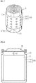
- Fig. 8 is a cross-sectional view schematically showing a secondary battery according to an embodiment of the present disclosure.
- the secondary battery according to the present disclosure includes an electrode assembly 10, a battery case 20 and a seal tape 100.
- the electrode assembly 10 includes a cathode plate and an anode plate disposed with a separator being interposed between them and rolled in a jelly roll shape, and the electrode assembly 10 is received in the battery case 20.
- the seal tape 100 is attached to the outer surface of the electrode assembly 10 including the rolling end 11.
- the battery case 20 receives the electrolyte together with the electrode assembly 10.
- the battery case 20 may generally have a cylindrical or rectangular shape, and Fig. 8 shows that the battery case 20 has a cylindrical shape.
- the seal tape 100 has an adhesive layer and adheres to the outer surface of the electrode assembly 10 and the inner surface of the battery case 20.
- the seal tape 100 has a first adhesive layer 110 and a second adhesive layer 120, where the first adhesive layer 110 is an adhesive layer adhered to the outer surface of the electrode assembly 10, and the second adhesive layer 120 is an adhesive layer having an adhesive surface opposite to the adhesive surface of the first adhesive layer 110 and adhered to the inner surface of the battery case 20.
- the seal tape 100 since the seal tape 100 according to the present disclosure includes the first adhesive layer 110 and the second adhesive layer 120, it may adhere to the electrode assembly 10 and the battery case 20 and prevent the electrode assembly 10 from moving. Therefore, it is possible to prevent the movement of the electrode assembly 10 from cutting an electrode lead 40, deforming or damaging the electrode assembly 10, separating or damaging a cap assembly 30, and consequently making the electrolyte leak.
- first adhesive layer 110 and the second adhesive layer 120 may be made of the same adhesive material, and at this time, the first adhesive layer 110 and the second adhesive layer 120 will exhibit as a single adhesive layer without being distinguished.
- the second adhesive layer 120 and the secondary battery may be made of material which exhibits an adhesive property by reacting with the electrolyte.
- the second adhesive layer 120 of the seal tape 100 may not have an adhesive property before it reacts with the electrolyte and preferably have an adhesive property after it reacts with the electrolyte.
- the electrode assembly 10 to which the seal tape 100 is attached may be easily inserted into the battery case 20 as described above.
- the second adhesive layer 120 may be made of OPS material.
- the second adhesive layer 120 may be an OPS film.
- the second adhesive layer 120 namely the OPS film, generally does not have an adhesive property, but it may have an adhesive property by reacting with a certain component such as the DMC of the electrolyte. Therefore, if the electrode assembly 10 according to the present disclosure to which the seal tape 100 is attached is inserted into the battery case 20 and then the electrolyte is injected thereto, the adhesive property of the OPS film is exhibited so that the OPS film may adhere to the inner surface of the battery case 20.
- the second adhesive layer 120 may be made of thermosetting adhesive material. Therefore, when the electrode assembly 10 is inserted into the battery case 20, the adhesive property of the second adhesive layer 120 is not exhibited, and the adhesive property of the second adhesive layer 120 may be exhibited by applying heat more than the predetermined level to the inside of the battery case 20 after the electrode assembly 10 is inserted into the battery case 20. Therefore, when the electrode assembly 10 is inserted into the battery case 20, it is possible to prevent the inserting process from being disturbed due to the adhesive characteristic of the second adhesive layer 120.
- the seal tape 100 further includes the protective layer 130 on the second adhesive layer 120.
- the protective layer 130 is partially removed by reacting with the electrolyte. At this time, the described configuration where the protective layer 130 is entirely removed from the seal tape 100 attached to the electrode assembly 10 is identical to Fig. 8 .
- the protective layer 130 is present in the upper portion of the second adhesive layer 120, namely at the outermost side of the seal tape 100, the adhesive surface of the seal tape 100 is not exposed. Therefore, the electrode assembly 10 may be inserted into the battery case 20 without any special difficulty. In addition, if the electrolyte is injected after the electrode assembly 10 is inserted into the battery case 20, the protective layer 130 reacts with the electrolyte and is removed, and therefore the second adhesive layer 120 is exposed at last so that the seal tape 100 and the battery case 20 adheres to each other.
- the protective layer 130 of the seal tape 100 is an OPS film made of OPS material.
- the protective layer 130 of the seal tape 100 may have an adhesive property entirely or partially by reacting with the electrolyte.
- the adhesive force of the second adhesive layer 120 and the protective layer 130 is reinforced, and therefore the adhesion between the seal tape 100 and the battery case 20 may become stronger.
- the substrate layer 140 may be further included between the first adhesive layer 110 and the second adhesive layer 120.
- the seal tape 100 may swell by reacting with the electrolyte.
- Fig. 9 is a cross-sectional view schematically showing the seal tape 100 swelling before and after the electrolyte is injected according to an embodiment of the present disclosure.
- (a) represents the configuration of the seal tape 100 before the electrolyte is injected into the secondary battery
- (b) of Fig. 9 represents the configuration of the seal tape 100 after the electrolyte is injected into the secondary battery.
- the thickness of the seal tape 100 attached to the electrode assembly 10 is t1, which is smaller than a gap g between the electrode assembly 10 and the battery case 20. Therefore, the electrode assembly 10 to which the seal tape 100 is attached may be easily inserted into the battery case 20.
- the tape 100 reacts with the electrolyte so that its thickness t2 may be equal to or greater than the gap g between the electrode assembly 10 and the battery case 20.
- the increase in thickness as described above increases the adhesion of the seal tape 100 between the first adhesive layer 110 and the electrode assembly 10, and the adhesion of the seal tape 100 between the second adhesive layer 120 and the battery case 20. Therefore, as a result, the electrode assembly 10 is strongly adhered to the battery case 20, thereby more securely preventing the electrode assembly 10 from moving.
- Figs. 8 and 9 illustrate the secondary battery where a beading portion is formed at the battery case 20
- the present disclosure may also be applied to a secondary battery having no beading portion.
- the battery case is free from a beading portion and the battery case has a cylindrical shape.
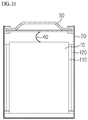
- Fig. 10 is a cross-sectional view schematically showing the secondary battery having no beading portion according to another embodiment of the present disclosure.
- a beading portion is not provided to the battery case 20.
- the electrode assembly 10 may easily move vertically. Therefore, a power insensitive phenomenon or other problems such as firing and explosion tend to easily occur due to the cutting of the electrode lead 40 or the damage of the electrode assembly 10.
- the cap assembly 30 is coupled with the battery case 20 by means of welding or the like, and, if an impact is applied to the lower portion of the cap assembly 30 due to the movement of the electrode assembly 10, the coupling portion may break, which may cause the electrolyte to leak or the cap assembly 30 to separate.
- the seal tape 100 according to the present disclosure is attached to the electrode assembly 10 and inserted into the battery case 20
- the first adhesive layer 110 and the second adhesive layer 120 are strongly adhered to the electrode assembly 10 and the battery case 20 to prevent the electrode assembly 10 from moving. Therefore, various problems caused by the movement of the electrode assembly 10 in the secondary battery having no beading portion may definitely be prevented.
- the present disclosure is not limited to such a specific shape of the secondary battery.
- the present disclosure may be applied to a rectangular secondary battery and a pouch type secondary battery.
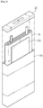
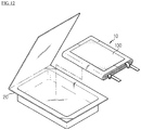
- Figs. 11 and 12 are schematic views showing a secondary battery according to still another embodiment of the present disclosure.
- the seal tape 100 is attached to the outer surface of the electrode assembly 10 rolled in a rectangular shape, and the electrode assembly 10 to which the seal tape 100 is attached as described above is received in the rectangular battery case 20 together with the electrolyte and is then closed by the cap assembly 30, according to the present disclosure.
- the seal tape 100 attached to the electrode assembly 10 may be attached to the inner surface of the rectangular battery case 20 by the second adhesive layer 120, similar to the cylindrical battery, thereby preventing the electrode assembly 10 from moving in the battery case 20.
- the electrode assembly 10 to outer surface of which the seal tape 100 is attached is received in the pouch type battery case 20 according to the present disclosure.
- the secondary battery may be configured so that the upper pouch covers the received electrode assembly 10.
- the seal tape 100 according to the present disclosure may also be attached to the electrode assembly 10 of the pouch type secondary battery.
- the seal tape 100 attached to the outer surface of the electrode assembly 10 may be attached to the inner surface of the pouch by the second adhesive layer 120 to prevent the electrode assembly 10 from moving in the pouch, namely in the battery case 20.
- Figs. 11 and 12 are just examples, and it is apparent to those having ordinary skill in the art that they may be implemented in various ways.
Description
- The present disclosure relates to a secondary battery and a seal tape used for the same, and more particularly, to a seal tape attached to the outer surface of an electrode assembly to prevent the electrode assembly from being released or moved.
- Generally, a secondary battery refers to a rechargeable battery, while a general battery refers to a non-rechargeable battery. Secondary batteries are widely used for electronic devices such as cellular phones, notebook computers, video cameras, electric vehicles, or the like. In particular, a lithium secondary battery has an operating voltage of about 3.6 V, triple the capacity of nickel-cadmium batteries or nickel hydrogen batteries generally used as power sources of electronic devices, and due to its high energy density per unit weight, are being utilized more and more.
- The lithium secondary battery generally uses lithium oxide and carbonaceous material as cathode active material and anode active material, respectively. The lithium secondary battery includes an electrode assembly in which a cathode plate and an anode plate respectively coated with the cathode active material and the anode active material are disposed with a separator being interposed between them, and an exterior material which seals and receives the electrode assembly together with an electrolyte.
- Meanwhile, the lithium secondary battery may be classified into a can type secondary battery where the electrode assembly is included in a metal can and a pouch type battery where the electrode assembly is included in a pouch of an aluminum laminate depending on the shape of the battery case. In addition, the can type secondary battery may further be classified into a cylindrical battery and a rectangular battery depending on the shape of the metal can.
- The electrode assembly is classified into a jelly roll type electrode assembly where a separator is interposed between the cathode plate and the anode plate and then rolled, and a stack type electrode assembly where separators are interposed between a plurality of cathode plates and anode plates with a predetermined size and then successively laminated. The stack type electrode assembly is generally used for a pouch type battery, and the jelly roll type electrode assembly is generally used for a can type secondary battery. In particular, the jelly roll type electrode assembly is widely used due to its advantages such as easy fabrication, high energy density per weight, and easy storage in a cylindrical or rectangular battery can.
- In the jelly roll type electrode assembly, also called "jelly roll" due to its shape, the cathode plate, the anode plate and the separator are laminated and rolled. Here, a seal tape is attached to the outermost terminal or a rolling end of the electrode assembly, so that the electrode assembly may maintain its rolled state without being released. In addition, the electrode assembly to which the seal tape is attached as described above is received in a metal can together with an electrolyte, and a cap assembly having an electrode terminal is coupled to the upper opening end of the battery case.
- However, the secondary battery having the above configuration has a problem in that the electrode assembly may move vertically or horizontally in the battery if the battery falls or external impact is applied thereto. Such movement of the electrode assembly may cut a tap connected between the electrode assembly and the cap assembly, which may cause a power insensitive phenomenon of the secondary battery. In addition, the vertical movement of the electrode assembly presses the upper or lower portion of the electrode assembly to deform the electrode assembly and cause a short circuit, which may break the secondary battery and lead to accidents such as firing or explosion, causing great damage. Moreover, the vertical movement of the electrode assembly may give impact to the cap assembly coupled to the upper opening portion of the secondary battery, causing the sealing portion to break or separate, which may lead to the electrolyte in the secondary battery to leak.
-
EP 2 273 601 A1 relates to a secondary battery which includes i) an electrode assembly, ii) an electrolyte, iii) a tape attached to at least part of an outer surface of the electrode assembly and iv) a case accommodating the electrode assembly, electrolyte and tape. -
EP 1 804 320 A2 relates to an electrode assembly for a lithium ion secondary battery and a lithium ion secondary battery using the same. - The present disclosure is designed to solve the problems of the prior art, and therefore it is an object of the present disclosure to provide a seal tape capable of preventing an electrode assembly from moving in a secondary battery, and a secondary battery using the same.
- Other objects and advantages of the present disclosure will be understood from the following description and become more apparent by embodiments of the present disclosure. In addition, it could be easily understood that the objects and advantages of the present disclosure can be implemented by means and their combinations defined in the claims.
- The present invention is as defined in the attached set of claims.
- It is also described a seal tape for a secondary battery as in claim 1, which is attached to an outer surface of an electrode assembly, which is received in a battery case, the seal tape including: a first adhesive layer having an adhesive surface adhered to the outer surface of the electrode assembly; and a second adhesive layer having an adhesive surface at a side opposite to the adhesive surface of the first adhesive layer so as to adhere to an inner surface of the battery case.
- Preferably, the second adhesive layer exhibits an adhesive property by reacting with an electrolyte of the secondary battery.
- Also the seal tape further includes a protective layer formed on the second adhesive layer, wherein the protective layer is partially removed by reacting with an electrolyte of the secondary battery.
- According the present invention, there is provided a secondary battery as defined in the attached set of claims, which includes: an electrode assembly including a cathode plate and an anode plate disposed with a separator being interposed between them; a battery case receiving the electrode assembly and an electrolyte; and a seal tape having a first adhesive layer adhered to an outer surface of the electrode assembly and a second adhesive layer with an adhesive surface formed at a side opposite to the adhesive surface of the first adhesive layer so as to adhere to an inner surface of the battery case.
- Preferably, the second adhesive layer exhibits an adhesive property by reacting with the electrolyte.
- The seal tape further includes a protective layer formed on the second adhesive layer and is partially removed by reacting with the electrolyte.
- According to the present disclosure, it is possible to prevent the electrode assembly in a rolled state from being released in the secondary battery and to prevent the electrode assembly from moving in the battery case.
- Therefore, it is possible to prevent a power insensitive phenomenon which can be caused by the movement of the electrode assembly cutting the electrode lead connected to the cap assembly.
- In addition, by preventing the impact applied to the upper or lower portion of the electrode assembly due to the movement of the electrode assembly, it is possible to prevent the secondary battery from damaging or causing accidents such as firing or explosion due to the short circuit caused by deformation of the electrode assembly.
- Further, in an embodiment of the present disclosure, when the seal tape is impregnated with the electrolyte in the secondary battery, the seal tape swells. In this case, the swelling seal tape may play a role of absorbing the impact transferred from the outside of the secondary battery to the electrode assembly. Therefore, the electrode assembly may be more stably protected.
- In addition, according to the present disclosure, by preventing the impact applied to the cap assembly due to the vertical movement of the electrode assembly, the breaking of the coupling portion between the cap assembly and the battery case can be prevented. Therefore, it is possible to prevent the electrolyte from leaking caused by the damage of the coupling portion of the cap assembly.
- Other objects and aspects of the present disclosure will become apparent from the following descriptions of the embodiments with reference to the accompanying drawings in which:
-
Fig. 1 is a cross-sectional view schematically showing a seal tape for a secondary battery according to an embodiment of the present disclosure; -
Fig. 2 is a cross-sectional view schematically showing a seal tape for a secondary battery according to another embodiment of the present disclosure; -
Fig. 3 is a cross-sectional view schematically showing a protective layer of the seal tape that is partially removed by reacting with an electrolyte, according to an embodiment of the present disclosure; -
Fig. 4 is a cross-sectional view schematically showing a seal tape for a secondary battery according to still another embodiment of the present disclosure; -
Fig. 5 is a schematic view showing the seal tape attached to an electrode assembly according to an embodiment of the present disclosure; -
Fig. 6 is a schematic view showing the seal tape attached to an electrode assembly according to another embodiment of the present disclosure; -
Fig. 7 is a schematic view showing the seal tape attached to an electrode assembly according to still another embodiment of the present disclosure; -
Fig. 8 is a cross-sectional view schematically showing a secondary battery according to an embodiment of the present disclosure; -
Fig. 9 is a cross-sectional view schematically showing the seal tape swelling before and after the electrolyte is injected according to an embodiment of the present disclosure; -
Fig. 10 is a cross-sectional view schematically showing a secondary battery having no beading portion according to the present invention; and -
Figs. 11 and12 are schematic views showing a secondary battery according to still another embodiment of the present disclosure. - Hereinafter, preferred embodiments of the present disclosure will be described in detail with reference to the accompanying drawings. Prior to the description, it should be understood that the terms used in the specification and the appended claims should not be construed as limited to general and dictionary meanings, but interpreted based on the meanings and concepts corresponding to technical aspects of the present disclosure on the basis of the principle that the inventor is allowed to define terms appropriately for the best explanation.
-
Fig. 1 is a partial cross-sectional view schematically showing aseal tape 100 for a secondary battery according to an embodiment of the present disclosure. - Referring to
Fig. 1 , theseal tape 100 for a secondary battery according to the present disclosure includes a firstadhesive layer 110 and a secondadhesive layer 120. - The first
adhesive layer 110 is a layer formed on one surface of theseal tape 100 so that it may adhere to the outer surface of an electrode assembly. In a case where theseal tape 100 is attached to an electrode assembly, the adhesive surface of the firstadhesive layer 110 directly adheres to the outer circumference of the electrode assembly. The firstadhesive layer 110 is made of adhesive material generally used in seal tapes of a secondary battery, or various kinds of other adhesive material may also be used. The firstadhesive layer 110 adhered to the electrode assembly is well known in the art and not described here in detail. In addition, the present disclosure is not limited to the material or manufacturing method of the firstadhesive layer 110, and various kinds of adhesive materials known in the art at the filing of this application may be used as the material of the firstadhesive layer 110. - The second
adhesive layer 120 is an adhesive layer having an adhesive surface at a surface opposite to the adhesive surface of the firstadhesive layer 110. Due to the secondadhesive layer 120, theseal tape 100 for a secondary battery according to the present disclosure is formed to have adhesive layers on both surfaces, different from a general seal tape for a secondary battery which has an adhesive layer on only one surface. The secondadhesive layer 120 is configured so that its adhesive surface directly contacts and adheres to the inner surface of the battery case in a case where the electrode assembly is received in the battery case. - The second
adhesive layer 120 may be made of the same adhesive material as the firstadhesive layer 110. Therefore, even though the figures of the firstadhesive layer 110 and the secondadhesive layer 120 distinguishably are configured to illustrate the separate layers for the sake of convenience, in a case where the secondadhesive layer 120 and the firstadhesive layer 110 are made of the same adhesive material, they may be in the form of a indistinguishable single adhesive layer. - Meanwhile, the second
adhesive layer 120 may be made of adhesive material different from the firstadhesive layer 110. - Preferably, the second
adhesive layer 120 exhibits an adhesive property by reacting with the secondary battery. In other words, the secondadhesive layer 120 of theseal tape 100 does not have an adhesive property before it reacts with the electrolyte, but preferably has an adhesive property after it reacts with the electrolyte. According to this embodiment, when the electrode assembly to which theseal tape 100 is attached is inserted into a battery case, the adhesive property of the secondadhesive layer 120 is not exhibited, and the adhesive property of the secondadhesive layer 120 is exhibited only after the electrode assembly is inserted into the battery case and the electrolyte is injected thereto. Therefore, the electrode assembly to which theseal tape 100 is attached may be easily inserted into the battery case. - In an embodiment not according to the invention, the second
adhesive layer 120 is made of oriented polystyrene (OPS). In other words, the secondadhesive layer 120 may be an OPS film. In a case where the secondadhesive layer 120 is an OPS film as described above, the secondadhesive layer 120, namely the OPS film, does not have an adhesive property, but it may have an adhesive property when reacting with a certain component of the electrolyte, for example dimethyl carbonate (DMC). In more detail, the OPS film is a solid film and generally does not have an adhesive property. However, if the OPS film reacts with the DMC, the DMC penetrates the pores of the polymer chains so that the polymer chains changes to a movable state allowing easy movement and has an adhesive property. In other words, the OPS film reacts with the DMC to shift its phase from a solid state to a viscous liquid state, which gives an adhesive property. Therefore, in a case where an electrolyte is injected into the battery case, in which the electrode assembly to which theseal tape 100 is attached is inserted, the adhesive property of the OPS film is exhibited, which allows the adhesion with the inner surface of the battery case. - Meanwhile, the OPS film, which has reacted with the electrolyte to shift its phase into a viscous liquid state as described above, may start a shrinking reaction by thermal treatment of about 60°C and become slowly solidified while losing the solvent component little by little. Therefore, in a case where the second
adhesive layer 120 is made of an OPS film like the above embodiment, the OPS film may be solidified again by performing a thermal treatment process, a predetermined time after the electrolyte is injected into the battery case. At this time, the thermal treatment process may be a process included in an existing secondary battery manufacturing process or an additional separate process. - In addition, even though it has been illustrated that the component of the electrolyte reacting with the OPS film to exhibit an adhesive property of the OPS film is the DMC, it is merely just an example, and the OPS film may exhibit its adhesive property by means of other nonpolar solvents such as toluene and xylene.
- Meanwhile, in a case where the second
adhesive layer 120 is made of an OPS film like in the above embodiment, the firstadhesive layer 110 may substantially have a thickness of 7 µm, and the secondadhesive layer 120 may substantially have a thickness of 40 µm. However, the thicknesses of the firstadhesive layer 110 and the secondadhesive layer 120 are just an example, and the present disclosure is not limited to such specific thicknesses of the firstadhesive layer 110 and the secondadhesive layer 120. The thickness of theentire seal tape 100, or the thickness of the firstadhesive layer 110 or the secondadhesive layer 120 may be suitably determined according to various factors such as the kinds of the firstadhesive layer 110 and the secondadhesive layer 120, the size or rolling shape of the electrode assembly, the kind of electrolyte, the size and capacity of the battery case, the size or manufacturing process of the secondary battery, or the like. - In addition, it is described that the second
adhesive layer 120 may be made of thermosetting adhesive material which exhibits an adhesive property when heat more than a predetermined level is applied. In this case, when the electrode assembly is inserted into the battery case, the adhesive property of the secondadhesive layer 120 is not exhibited so that the electrode assembly may be inserted into the battery case without any disturbance from the secondadhesive layer 120. In addition, after the electrode assembly is inserted into the battery case, heat more than the predetermined level is applied to theseal tape 100 so that the secondadhesive layer 120 exhibits an adhesive property, which allows the secondadhesive layer 120 to adhere to the inner surface of the battery case. The heat applying process as described above may be included in an existing secondary battery manufacturing process or may be separately added. According to this embodiment, the electrode assembly to which theseal tape 100 is attached may be more easily received in the battery case. -
Fig. 2 is a partial cross-sectional view schematically showing aseal tape 100 for a secondary battery according to another embodiment of the present disclosure. - As shown in
Fig. 2 , theseal tape 100 for a secondary battery according to the present disclosure further includes aprotective layer 130 on the secondadhesive layer 120. - The
protective layer 130 is a non-adhesive layer with no adhesive property and prevents the secondadhesive layer 120 from being exposed out on the secondadhesive layer 120. In a state where theprotective layer 130 is present on the secondadhesive layer 120 so that the secondadhesive layer 120 is not exposed as described above, theseal tape 100 has a shape similar to a single-surface adhesive tape. Therefore, when the electrode assembly to which theseal tape 100 is attached is inserted into the battery case, it is possible to prevent the insertion process of the electrode assembly from being disturbed due to the adhesive property of the secondadhesive layer 120. - In the present invention, the
protective layer 130 reacts with the electrolyte of the secondary battery and is partially removed. In other words, when the electrode assembly to which theseal tape 100 is attached is received in the battery case together with the electrolyte, theprotective layer 130 at the periphery of theseal tape 100 may react with the electrolyte of theprotective layer 130 at the outer location so that it is partially removed. For example, theprotective layer 130 may be removed by reacting with the DMC of the electrolyte. If theprotective layer 130 is removed by reacting with the electrolyte as described above, theseal tape 100 converts from the single-surface adhesive tape form to a double-surface adhesive tape form. -
Fig. 3 is a cross-sectional view schematically showing aprotective layer 130 of theseal tape 100 that is partially removed by reacting with an electrolyte, according to an embodiment of the present disclosure. InFig. 3, (a) shows theseal tape 100 before it reacts with the electrolyte of the secondary battery, and (b) shows theseal tape 100 after it reacts with the electrolyte of the secondary battery. In addition, inFig. 3 , the firstadhesive layer 110 and the secondadhesive layer 120 are depicted as a single layer on the assumption that they are made of the same adhesive material. - Referring to
Fig. 3 , before it reacts with the electrolyte, theprotective layer 130 is present on the entire upper portion of the secondadhesive layer 120, which is an adhesive surface, and so the secondadhesive layer 120 may not be exposed out. For this reason, the adhesive characteristic of the secondadhesive layer 120 may not be exhibited. However, if theseal tape 100 reacts with the electrolyte, at least a part of theprotective layer 130 is removed. At this time, the secondadhesive layer 120 may be exposed out through the removed portion of theprotective layer 130. Therefore, the adhesive characteristic of the secondadhesive layer 120 may be exhibited, and at this time it may adhere to an adjacent object, for example the inner surface of the battery case. - Further, the second
adhesive layer 120 may increase its movement by applying an amount more than the predetermined level thereto or contacting the electrolyte during the secondary battery manufacturing process, so that the adhesive material of the secondadhesive layer 120 may leak through the region where theprotective layer 130 is removed as shown inFig. 3 . Therefore, the adhering area of the secondadhesive layer 120 may further increase. In this case, the adhesive force of the secondadhesive layer 120 may further improve. - Meanwhile, even though
Fig. 3 shows that theprotective layer 130 is partially removed by reacting with the electrolyte, it is also described in an embodiment not according to the invention, that theprotective layer 130 is entirely removed by reacting with the electrolyte. In this case, as shown in (a) ofFig. 3 , theseal tape 100 may have a similar shape as shown inFig. 1 as theprotective layer 130 is entirely removed by reacting with the electrolyte. Therefore, the entire adhesive surface of the secondadhesive layer 120 may be exposed thereby contacting the battery case. - In the present invention, the
protective layer 130 has partially an adhesive property by reacting with the electrolyte. In other words, theprotective layer 130 does not have an adhesive property before it reacts with the electrolyte but has an adhesive property by reacting with the electrolyte so that it may serve as an adhesive layer. Therefore, when the electrode assembly to which theseal tape 100 is attached is inserted into the battery case, the adhesive characteristic of theprotective layer 130 is not exhibited so that the inserting process may be easily performed, and if the electrolyte is inserted after the electrode assembly is inserted, the adhesive characteristic of theprotective layer 130 may be exhibited so that theprotective layer 130 adheres to the inner surface of the battery case. - The present disclosure is not limited to the detailed material of the
protective layer 130, and various kinds of polymer material may be used for theprotective layer 130. - In the present invention, the
protective layer 130 is made of OPS material. Such an OPSprotective layer 130 may be attached onto the secondadhesive layer 120 of theseal tape 100 in an OPS film form and then, by the DMC contained in the electrolyte, dissolve or be removed when reacting with the electrolyte. Therefore, the secondadhesive layer 120 located below the OPSprotective layer 130 may be exposed thereby contacting the battery case. In addition, the OPSprotective layer 130 may have an adhesive property just by being dissolved by the DMC. - In addition, the
protective layer 130 may have various thicknesses. In other words, theprotective layer 130 may have various thicknesses according to the material of theprotective layer 130, the thicknesses of the firstadhesive layer 110 and the secondadhesive layer 120, the size or rolled state of the electrode assembly, the kind of the electrolyte, the size or capacity of the battery case, the size or manufacturing process of the secondary battery, or the like. -
Fig. 4 is a partial sectional view schematically showing aseal tape 100 for a secondary battery according to still another embodiment of the present disclosure. - Referring to
Fig. 4 , theseal tape 100 for a secondary battery according to the present disclosure may further include asubstrate layer 140 between the firstadhesive layer 110 and the secondadhesive layer 120. Thesubstrate layer 140 is a non-adhesive layer interposed between the firstadhesive layer 110 and the secondadhesive layer 120, and the present disclosure is not limited to the material or shape of thesubstrate layer 140. For example, thesubstrate layer 140 may be made of various kinds of material. In more detail, thesubstrate layer 140 may be made of polymer material such as polypropylene, polyethylene or polyimide. In addition, thesubstrate layer 140 may have various thicknesses according to the size or manufacturing process of the secondary battery, the size of the electrode assembly, the thicknesses of the firstadhesive layer 110 and the secondadhesive layer 120, the presence or thickness of theprotective layer 130, the capacity of the battery case, or the like. For example, the thickness of thesubstrate layer 140 may be determined so that the entire thickness of the firstadhesive layer 110, thesubstrate layer 140 and the secondadhesive layer 120 becomes 50 µm. - Meanwhile, the adhesive surface of the second
adhesive layer 120 may have a shape different from the adhesive surface of the firstadhesive layer 110. For example, as shown inFig. 4 , the size of the adhering area of the secondadhesive layer 120 may be smaller than the size of the adhering area of the firstadhesive layer 110. Further details regarding the shapes of the secondadhesive layer 120 will be described with reference toFigs. 5 to 7 . -
Fig. 5 is a schematic view showing theseal tape 100 attached to anelectrode assembly 10 according to an embodiment of the present disclosure - Referring to
Fig. 5 , theseal tape 100 for a secondary battery is attached to entirely or partially surround the outer circumference of theelectrolyte assembly 10 having a rollingend 11 of theelectrode assembly 10 rolled in a jelly roll shape. Since the rollingend 11 of theelectrode assembly 10 is fixed by theseal tape 100 as described above, theelectrode assembly 10 is not released but maintains the rolled state. - As shown in
Fig. 5 , the secondadhesive layer 120 of theseal tape 100 may have the same shape and size as the firstadhesive layer 110. In this case, only the secondadhesive layer 120 of theseal tape 100 attached to theelectrode assembly 10 is exposed out. If the secondadhesive layer 120 is formed on the entire area of theseal tape 100 as described above, the adhesive force between theseal tape 100 and the battery case may be improved. At this time, the sectional shape of the seal tape along the line A-A' may be shown as inFig. 1 . In addition, though not shown in the figures, theprotective layer 130 may be formed in the upper portion of the secondadhesive layer 120, namely the outermost side of theseal tape 100. - Meanwhile, the width, namely vertical length, of the
seal tape 100 attached to theelectrode assembly 10 may be variously configured. For example, assuming that the vertical length of theelectrode assembly 10 is 60 mm, the vertical length of theseal tape 100 may be 50 mm. However, the present disclosure is not limited to such a specific attachment size of theseal tape 100, and theseal tape 100 may be attached to theelectrode assembly 10 of various sizes. -
Fig. 6 is a schematic view showing the seal tape attached to anelectrode assembly 10 according to another embodiment of the present disclosure. - As shown in
Fig. 6 , theseal tape 100 for a secondary battery attached to the outer surface of theelectrode assembly 10 including the rollingend 11 may include a plurality of stripe-type secondadhesive layers 120 attached to the outer surface thereof. In other words, the secondadhesive layers 120 and the firstadhesive layer 110 may have shapes and sizes different from each other. In this case, thesubstrate layer 140 may be provided between the firstadhesive layer 110 and the secondadhesive layer 120. In addition, in the case of theseal tape 100, the sectional shape along the line B-B' may be depicted as shown inFig. 4 . In the present invention, theprotective layer 130 is formed on the secondadhesive layer 120. -
Fig. 7 is a schematic view showing the seal tape attached to anelectrode assembly 10 according to still another embodiment of the present disclosure. - As shown in
Fig. 7 , theseal tape 100 for a secondary battery according to the present disclosure may include a plurality of dot-type secondadhesive layers 120 with a certain size and shape. At this time, each secondadhesive layer 120 may be consistent by having same shapes such as a rectangle or a triangle or may have different shapes. In addition, inFig.7 , like in the embodiment shown inFig. 6 , thesubstrate layer 140 may be provided between the firstadhesive layer 110 and the secondadhesive layer 120. In the case of theseal tape 100 of the embodiment shown inFig. 7 , the sectional shape along the line C-C' may be depicted as shown inFig. 4 , similar toFig. 6 . In the present invention, theprotective layer 130 is formed on the secondadhesive layer 120. - Meanwhile, the configurations of the
seal tape 100 for a secondary battery as shown inFigs. 5 to 7 are just examples. It is obvious to those having ordinary skill in the art that the attachment state of theseal tape 100 to theelectrode assembly 10 and the size, shape or the like of the secondadhesive layer 120 may be variously modified, other than those shown inFigs. 5 to 7 . - Preferably, the
seal tape 100 may swell by reacting with the electrolyte of the secondary battery. In this case, before theelectrode assembly 10 to which theseal tape 100 is attached is inserted into the battery case, theseal tape 100 does not react with the electrolyte, and therefore theseal tape 100 does not swell and theelectrode assembly 10 may be easily inserted into the battery case. In addition, if theelectrode assembly 10 is inserted into the battery case and then the electrolyte is injected thereto, theseal tape 100 on the outer surface of theelectrode assembly 10 reacts with the electrolyte and swells. The swelling of theseal tape 100 allows the secondadhesive layer 120 located at the outmost side to more strongly adhere to the inner surface of the battery case. Therefore, in a case where theseal tape 100 swells as in the above embodiment, theseal tape 100 and the battery case may adhere more strongly and easily. In addition, if theseal tape 100 swells, the impact transferred to theelectrode assembly 10 from the outside of the battery case may be relieved. - The
seal tape 100 may swell by reacting with the electrolyte in various ways. For example, the firstadhesive layer 110 and/or the secondadhesive layer 120 may react with the electrolyte and swell. In the present invention, the secondadhesive layer 120 is made of polyacrylate. In other cases, the firstadhesive layer 110 and/or the secondadhesive layer 120 may be made of poly methyl methacrylate (PMMA), poly ethyl methacrylate (PEMA), or poly butyl methacrylate (PBMA). In addition, thesubstrate layer 140 may react with the electrolyte and swell. In this case, thesubstrate layer 140 may be made of porous polymer material so that it may swell as it absorbs the electrolyte when impregnated with the electrolyte. The present disclosure is not limited to a detailed swelling shape of theseal tape 100, and theseal tape 100 may swell in various shapes. In addition, for this purpose, the firstadhesive layer 110, the secondadhesive layer 120 or thesubstrate layer 140 may be made of various materials. -
Fig. 8 is a cross-sectional view schematically showing a secondary battery according to an embodiment of the present disclosure. - Referring to
Fig. 8 , the secondary battery according to the present disclosure includes anelectrode assembly 10, abattery case 20 and aseal tape 100. - The
electrode assembly 10 includes a cathode plate and an anode plate disposed with a separator being interposed between them and rolled in a jelly roll shape, and theelectrode assembly 10 is received in thebattery case 20. In addition, theseal tape 100 is attached to the outer surface of theelectrode assembly 10 including the rollingend 11. - The
battery case 20 receives the electrolyte together with theelectrode assembly 10. Thebattery case 20 may generally have a cylindrical or rectangular shape, andFig. 8 shows that thebattery case 20 has a cylindrical shape. - The
seal tape 100 has an adhesive layer and adheres to the outer surface of theelectrode assembly 10 and the inner surface of thebattery case 20. In more detail, theseal tape 100 has a firstadhesive layer 110 and a secondadhesive layer 120, where the firstadhesive layer 110 is an adhesive layer adhered to the outer surface of theelectrode assembly 10, and the secondadhesive layer 120 is an adhesive layer having an adhesive surface opposite to the adhesive surface of the firstadhesive layer 110 and adhered to the inner surface of thebattery case 20. - As described above, since the
seal tape 100 according to the present disclosure includes the firstadhesive layer 110 and the secondadhesive layer 120, it may adhere to theelectrode assembly 10 and thebattery case 20 and prevent theelectrode assembly 10 from moving. Therefore, it is possible to prevent the movement of theelectrode assembly 10 from cutting anelectrode lead 40, deforming or damaging theelectrode assembly 10, separating or damaging acap assembly 30, and consequently making the electrolyte leak. - Meanwhile, the first
adhesive layer 110 and the secondadhesive layer 120 may be made of the same adhesive material, and at this time, the firstadhesive layer 110 and the secondadhesive layer 120 will exhibit as a single adhesive layer without being distinguished. - Preferably, the second
adhesive layer 120 and the secondary battery may be made of material which exhibits an adhesive property by reacting with the electrolyte. In other words, the secondadhesive layer 120 of theseal tape 100 may not have an adhesive property before it reacts with the electrolyte and preferably have an adhesive property after it reacts with the electrolyte. In this case, theelectrode assembly 10 to which theseal tape 100 is attached may be easily inserted into thebattery case 20 as described above. - It is also described that the second
adhesive layer 120 may be made of OPS material. In other words, the secondadhesive layer 120 may be an OPS film. In a case where the secondadhesive layer 120 is an OPS film as described above, the secondadhesive layer 120, namely the OPS film, generally does not have an adhesive property, but it may have an adhesive property by reacting with a certain component such as the DMC of the electrolyte. Therefore, if theelectrode assembly 10 according to the present disclosure to which theseal tape 100 is attached is inserted into thebattery case 20 and then the electrolyte is injected thereto, the adhesive property of the OPS film is exhibited so that the OPS film may adhere to the inner surface of thebattery case 20. - In addition, it is described that the second
adhesive layer 120 may be made of thermosetting adhesive material. Therefore, when theelectrode assembly 10 is inserted into thebattery case 20, the adhesive property of the secondadhesive layer 120 is not exhibited, and the adhesive property of the secondadhesive layer 120 may be exhibited by applying heat more than the predetermined level to the inside of thebattery case 20 after theelectrode assembly 10 is inserted into thebattery case 20. Therefore, when theelectrode assembly 10 is inserted into thebattery case 20, it is possible to prevent the inserting process from being disturbed due to the adhesive characteristic of the secondadhesive layer 120. - In the present invention, the
seal tape 100 further includes theprotective layer 130 on the secondadhesive layer 120. Theprotective layer 130 is partially removed by reacting with the electrolyte. At this time, the described configuration where theprotective layer 130 is entirely removed from theseal tape 100 attached to theelectrode assembly 10 is identical toFig. 8 . - In this embodiment, since the
protective layer 130 is present in the upper portion of the secondadhesive layer 120, namely at the outermost side of theseal tape 100, the adhesive surface of theseal tape 100 is not exposed. Therefore, theelectrode assembly 10 may be inserted into thebattery case 20 without any special difficulty. In addition, if the electrolyte is injected after theelectrode assembly 10 is inserted into thebattery case 20, theprotective layer 130 reacts with the electrolyte and is removed, and therefore the secondadhesive layer 120 is exposed at last so that theseal tape 100 and thebattery case 20 adheres to each other. - At this time, the
protective layer 130 of theseal tape 100 is an OPS film made of OPS material. - In addition, the
protective layer 130 of theseal tape 100 may have an adhesive property entirely or partially by reacting with the electrolyte. In this case, the adhesive force of the secondadhesive layer 120 and theprotective layer 130 is reinforced, and therefore the adhesion between theseal tape 100 and thebattery case 20 may become stronger. - In addition, though not shown in
Fig. 8 , thesubstrate layer 140 may be further included between the firstadhesive layer 110 and the secondadhesive layer 120. - Preferably, the
seal tape 100 may swell by reacting with the electrolyte. -
Fig. 9 is a cross-sectional view schematically showing theseal tape 100 swelling before and after the electrolyte is injected according to an embodiment of the present disclosure. InFig. 9, (a) represents the configuration of theseal tape 100 before the electrolyte is injected into the secondary battery, and (b) ofFig. 9 represents the configuration of theseal tape 100 after the electrolyte is injected into the secondary battery. - Referring to (a) of
Fig. 9 , before the electrolyte is injected, the thickness of theseal tape 100 attached to theelectrode assembly 10 is t1, which is smaller than a gap g between theelectrode assembly 10 and thebattery case 20. Therefore, theelectrode assembly 10 to which theseal tape 100 is attached may be easily inserted into thebattery case 20. - Meanwhile, referring to (b) of
Fig. 9 , in a case where the electrolyte is injected into thebattery case 20, thetape 100 reacts with the electrolyte so that its thickness t2 may be equal to or greater than the gap g between theelectrode assembly 10 and thebattery case 20. However, since the gap between theelectrode assembly 10 and thebattery case 20 is given, the increase in thickness as described above increases the adhesion of theseal tape 100 between the firstadhesive layer 110 and theelectrode assembly 10, and the adhesion of theseal tape 100 between the secondadhesive layer 120 and thebattery case 20. Therefore, as a result, theelectrode assembly 10 is strongly adhered to thebattery case 20, thereby more securely preventing theelectrode assembly 10 from moving. - Meanwhile, though
Figs. 8 and9 illustrate the secondary battery where a beading portion is formed at thebattery case 20, the present disclosure may also be applied to a secondary battery having no beading portion. According to the invention, the battery case is free from a beading portion and the battery case has a cylindrical shape. -
Fig. 10 is a cross-sectional view schematically showing the secondary battery having no beading portion according to another embodiment of the present disclosure. - Referring to
Fig. 10 , different fromFigs. 8 and9 , a beading portion is not provided to thebattery case 20. In the case of the secondary battery having no beading portion as described above, theelectrode assembly 10 may easily move vertically. Therefore, a power insensitive phenomenon or other problems such as firing and explosion tend to easily occur due to the cutting of theelectrode lead 40 or the damage of theelectrode assembly 10. In addition, thecap assembly 30 is coupled with thebattery case 20 by means of welding or the like, and, if an impact is applied to the lower portion of thecap assembly 30 due to the movement of theelectrode assembly 10, the coupling portion may break, which may cause the electrolyte to leak or thecap assembly 30 to separate. - However, in a case where the
seal tape 100 according to the present disclosure is attached to theelectrode assembly 10 and inserted into thebattery case 20, the firstadhesive layer 110 and the secondadhesive layer 120 are strongly adhered to theelectrode assembly 10 and thebattery case 20 to prevent theelectrode assembly 10 from moving. Therefore, various problems caused by the movement of theelectrode assembly 10 in the secondary battery having no beading portion may definitely be prevented. - Meanwhile, even though the above embodiments have been illustrated based on a cylindrical secondary battery, the present disclosure is not limited to such a specific shape of the secondary battery. For example, the present disclosure may be applied to a rectangular secondary battery and a pouch type secondary battery.
-
Figs. 11 and12 are schematic views showing a secondary battery according to still another embodiment of the present disclosure. - Referring to
Fig. 11 , theseal tape 100 is attached to the outer surface of theelectrode assembly 10 rolled in a rectangular shape, and theelectrode assembly 10 to which theseal tape 100 is attached as described above is received in therectangular battery case 20 together with the electrolyte and is then closed by thecap assembly 30, according to the present disclosure. At this time, theseal tape 100 attached to theelectrode assembly 10 may be attached to the inner surface of therectangular battery case 20 by the secondadhesive layer 120, similar to the cylindrical battery, thereby preventing theelectrode assembly 10 from moving in thebattery case 20. - Referring to
Fig. 12 , theelectrode assembly 10 to outer surface of which theseal tape 100 is attached is received in the pouchtype battery case 20 according to the present disclosure. In other words, after theelectrode assembly 10 is received in a space formed in the lower pouch, the secondary battery may be configured so that the upper pouch covers the receivedelectrode assembly 10. Here, theseal tape 100 according to the present disclosure may also be attached to theelectrode assembly 10 of the pouch type secondary battery. In this case, theseal tape 100 attached to the outer surface of theelectrode assembly 10 may be attached to the inner surface of the pouch by the secondadhesive layer 120 to prevent theelectrode assembly 10 from moving in the pouch, namely in thebattery case 20. - Meanwhile, the rectangular secondary battery and the pouch type secondary battery shown in
Figs. 11 and12 are just examples, and it is apparent to those having ordinary skill in the art that they may be implemented in various ways. - The present disclosure has been described in detail. However, it should be understood that the detailed description and specific examples, while indicating preferred embodiments of the disclosure, are given by way of illustration. The invention is as set out in the set of attached claims.
Claims (6)
- A secondary battery, comprising:an electrode assembly (10) including a cathode plate and an anode plate disposed with a separator being interposed between them;a battery case (20) receiving the electrode assembly (10) and an electrolyte; anda seal tape (100) having a first adhesive layer (110) adhered to an outer surface of the electrode assembly (10) and a second adhesive layer (120) with an adhesive surface formed at a side opposite to the adhesive surface of the first adhesive layer (110) so as to adhere to an inner surface of the battery case (20),
characterized in that:- the battery case is free from a beading portion and the battery case has a cylindrical shape,- the seal tape (100) further includes a protective layer (130) which is formed on the second adhesive layer (120) and is partially removed by reacting with the electrolyte,- the protective layer (130) is made of OPS material, and- the second adhesive layer (120) is made of polyacrylate. - The secondary battery according to claim 1, wherein the second adhesive layer (120) exhibits an adhesive property by reacting with the electrolyte.
- The secondary battery according to claim 1, wherein the protective layer (130) entirely or partially has an adhesive property by reacting with the electrolyte.
- The secondary battery according to claim 1, wherein the seal tape (100) swells by reacting with the electrolyte.
- The secondary battery according to claim 1, wherein the first adhesive layer (110) and the second adhesive layer (120) are made of the same adhesive material.
- The secondary battery according to claim 1, wherein the seal tape further (100) includes a substrate layer (140) between the first adhesive layer (110) and the second adhesive layer (120).
Applications Claiming Priority (3)
| Application Number | Priority Date | Filing Date | Title |
|---|---|---|---|
| KR20100096444 | 2010-10-04 | ||
| PCT/KR2010/008006 WO2012046911A1 (en) | 2010-10-04 | 2010-11-12 | Seal tape and secondary battery using same |
| KR1020100112799A KR101198294B1 (en) | 2010-10-04 | 2010-11-12 | Seal tape and secondary battery using the same |
Publications (3)
| Publication Number | Publication Date |
|---|---|
| EP2477252A1 EP2477252A1 (en) | 2012-07-18 |
| EP2477252A4 EP2477252A4 (en) | 2017-02-22 |
| EP2477252B1 true EP2477252B1 (en) | 2020-08-19 |
Family
ID=46137138
Family Applications (1)
| Application Number | Title | Priority Date | Filing Date |
|---|---|---|---|
| EP10852643.5A Active EP2477252B1 (en) | 2010-10-04 | 2010-11-12 | Seal tape and secondary battery using the same |
Country Status (7)
| Country | Link |
|---|---|
| US (2) | US8980464B2 (en) |
| EP (1) | EP2477252B1 (en) |
| JP (2) | JP5579863B2 (en) |
| KR (1) | KR101198294B1 (en) |
| CN (1) | CN102549801B (en) |
| TW (2) | TWI487764B (en) |
| WO (1) | WO2012046911A1 (en) |
Families Citing this family (49)
| Publication number | Priority date | Publication date | Assignee | Title |
|---|---|---|---|---|
| WO2012102588A2 (en) * | 2011-01-27 | 2012-08-02 | 주식회사 엘지화학 | Swelling tape for filling gap |
| JP2014078389A (en) * | 2012-10-10 | 2014-05-01 | Toyota Industries Corp | Power storage device |
| KR20140064168A (en) * | 2012-11-19 | 2014-05-28 | 삼성에스디아이 주식회사 | Rechargeable lithium battery |
| KR20150004678A (en) * | 2013-07-03 | 2015-01-13 | 삼성에스디아이 주식회사 | Lithium pouch type battery |
| US10619079B2 (en) * | 2013-08-16 | 2020-04-14 | Lg Chem, Ltd. | Pressure-sensitive adhesive composition |
| KR102121737B1 (en) * | 2013-10-16 | 2020-06-11 | 삼성에스디아이 주식회사 | Secondary Battery |
| KR102154327B1 (en) | 2013-12-16 | 2020-09-09 | 삼성에스디아이 주식회사 | Jelly roll tape for rechargeable battery and rechargeable battery having the same |
| US20150188185A1 (en) * | 2013-12-31 | 2015-07-02 | Microsoft Corporation | Reinforcement of battery |
| CN203690420U (en) * | 2014-01-23 | 2014-07-02 | 东莞新能源科技有限公司 | Lithium ion battery |
| US9634351B2 (en) * | 2014-03-14 | 2017-04-25 | Apple Inc. | Mechanical structures for maintaining structural integrity in cylindrical pouch cell batteries |
| TWI651879B (en) | 2014-03-19 | 2019-02-21 | 日商積水化學工業股份有限公司 | Method for producing laminated layer type lithium ion secondary battery and laminated layer type lithium ion secondary battery |
| DE102014206890A1 (en) | 2014-04-10 | 2015-10-15 | Bayerische Motoren Werke Aktiengesellschaft | Method and device for at least partially manufacturing an electrical energy storage cell |
| CN105449255B (en) * | 2014-08-05 | 2019-01-08 | 东莞新能源科技有限公司 | Electrochemical energy storage device |
| CN106575736B (en) | 2014-09-29 | 2019-09-13 | 日本瑞翁株式会社 | Electro chemical elements use adhesive composite, electro chemical elements use adhesive layer and electrochemical element |
| CN105742712A (en) | 2014-12-08 | 2016-07-06 | 东莞新能源科技有限公司 | Electrochemical energy storage device |
| KR101851429B1 (en) | 2015-02-13 | 2018-04-23 | 주식회사 엘지화학 | Secondary battery |
| CN107431233B (en) | 2015-03-24 | 2020-09-08 | 日本电气株式会社 | Secondary battery, method for manufacturing secondary battery, electric vehicle, and power storage system |
| KR102337490B1 (en) * | 2015-05-26 | 2021-12-09 | 삼성에스디아이 주식회사 | Secondary Battery |
| KR20160142589A (en) * | 2015-06-03 | 2016-12-13 | 주식회사 엘지화학 | Cylindrical Secondary Battery |
| KR102125492B1 (en) * | 2015-09-22 | 2020-06-22 | 주식회사 엘지화학 | Method and apparatus for attaching seal tape to electrode assembly |
| US20180316045A1 (en) * | 2015-11-11 | 2018-11-01 | Nitto Denko Corporation | Adhesive tape |
| WO2017082418A1 (en) * | 2015-11-11 | 2017-05-18 | 日東電工株式会社 | Adhesive tape |
| KR102534101B1 (en) | 2015-11-12 | 2023-05-18 | 삼성에스디아이 주식회사 | Secondary battery |
| CN108352577B (en) * | 2015-12-01 | 2021-06-08 | 远景Aesc日本有限公司 | Lithium ion secondary battery and method for manufacturing same |
| KR102547065B1 (en) | 2016-02-29 | 2023-06-23 | 삼성에스디아이 주식회사 | Secondary battery |
| WO2017158701A1 (en) * | 2016-03-14 | 2017-09-21 | 株式会社村田製作所 | Electrical storage device |
| KR102214359B1 (en) | 2016-08-25 | 2021-02-08 | 삼성에스디아이 주식회사 | Rechargeable battery |
| KR102278442B1 (en) * | 2016-09-21 | 2021-07-16 | 삼성에스디아이 주식회사 | Rechargeable lithium battery |
| KR20220110610A (en) | 2016-10-14 | 2022-08-08 | 니폰 제온 가부시키가이샤 | Adhesive composition for electrochemical elements, electrochemical element and method for producing electrochemical element |
| KR102312279B1 (en) * | 2016-10-17 | 2021-10-12 | 삼성에스디아이 주식회사 | Rechargeable battery |
| JP7022909B2 (en) * | 2017-02-27 | 2022-02-21 | パナソニックIpマネジメント株式会社 | Revolving battery |
| KR102422921B1 (en) * | 2017-04-07 | 2022-07-20 | 주식회사 엘지에너지솔루션 | Cylindrical Battery Cell Comprising Jerry-roll Type Electrode Assembly with Tape for Preventing Stiffening of Adhesive Attached thereto |
| CN107746682A (en) * | 2017-08-17 | 2018-03-02 | 惠州瑞德新材料科技股份有限公司 | A kind of preparation method of acrylate swellable tape |
| KR102576645B1 (en) | 2017-10-26 | 2023-09-11 | 삼성전자주식회사 | Battery and electronic device including the same |
| WO2019124572A1 (en) * | 2017-12-18 | 2019-06-27 | 삼성에스디아이(주) | Finishing tape and secondary battery comprising same |
| KR102541550B1 (en) * | 2018-02-27 | 2023-06-08 | 삼성전자주식회사 | Electronic device including a battery structure |
| EP3813178A4 (en) | 2018-06-20 | 2021-07-28 | SANYO Electric Co., Ltd. | Nonaqueous electrolyte secondary battery |
| CN112236895A (en) | 2018-06-20 | 2021-01-15 | 三洋电机株式会社 | Nonaqueous electrolyte secondary battery |
| KR102599481B1 (en) | 2018-08-14 | 2023-11-08 | 삼성전자주식회사 | Battery adhesive structure, and electronic device with the same |
| KR20200037599A (en) * | 2018-10-01 | 2020-04-09 | 삼성에스디아이 주식회사 | Secondary battery |
| KR20220008684A (en) * | 2020-07-14 | 2022-01-21 | 주식회사 엘지에너지솔루션 | Button type secondary battery |
| CN111995957A (en) * | 2020-08-18 | 2020-11-27 | 澳中新材料科技(韶关)有限公司 | Oriented polystyrene expansion adhesive tape with high expansion ratio and preparation method thereof |
| KR20220105459A (en) | 2021-01-20 | 2022-07-27 | 주식회사 엘지에너지솔루션 | Manufacturing method of secondary battery |
| JP7467507B2 (en) * | 2021-01-29 | 2024-04-15 | 寧徳新能源科技有限公司 | Electrochemical and electronic devices |
| WO2023070669A1 (en) * | 2021-11-01 | 2023-05-04 | 东莞新能源科技有限公司 | Electrochemical apparatus and electronic apparatus including same |
| CN114267885A (en) * | 2021-12-21 | 2022-04-01 | 惠州亿纬锂能股份有限公司 | Anti-drop steel shell button battery and preparation method and application thereof |
| CN217409470U (en) | 2022-05-11 | 2022-09-13 | 苏州嘉树医疗科技有限公司 | Boosting mechanism suitable for liquid container |
| KR20240000819A (en) * | 2022-06-24 | 2024-01-03 | 삼성에스디아이 주식회사 | Secondary Battery |
| CN218677233U (en) * | 2022-08-12 | 2023-03-21 | 宁德时代新能源科技股份有限公司 | Battery cell, battery and power consumption device |
Citations (1)
| Publication number | Priority date | Publication date | Assignee | Title |
|---|---|---|---|---|
| US20090117459A1 (en) * | 2007-11-06 | 2009-05-07 | Samsung Sdi Co., Ltd. | Secondary battery and method of manufacturing the same |
Family Cites Families (24)
| Publication number | Priority date | Publication date | Assignee | Title |
|---|---|---|---|---|
| JP3321853B2 (en) * | 1992-10-30 | 2002-09-09 | ソニー株式会社 | Non-aqueous electrolyte secondary battery |
| JPH06181058A (en) * | 1992-12-14 | 1994-06-28 | Kureha Chem Ind Co Ltd | Looseness restraining means of wound electrode body for nonaqueous electrolyte type battery |
| US6743546B1 (en) * | 1999-03-26 | 2004-06-01 | Matsushita Electric Industrial Co., Ltd. | Laminate sheath type battery |
| US6379838B1 (en) * | 1999-04-14 | 2002-04-30 | Alcatel | Cell package |
| JP2001093576A (en) * | 1999-09-27 | 2001-04-06 | Japan Storage Battery Co Ltd | Non-aqueous electrolyte battery and manufacturing method thereof |
| JP2001273933A (en) * | 2000-03-27 | 2001-10-05 | Shin Kobe Electric Mach Co Ltd | Cylindrical lithium-ion battery |
| JP3831939B2 (en) * | 2001-11-12 | 2006-10-11 | ソニー株式会社 | battery |
| JP2005060412A (en) * | 2003-08-08 | 2005-03-10 | Three M Innovative Properties Co | Sealing tape |
| KR100542677B1 (en) * | 2004-06-25 | 2006-01-11 | 삼성에스디아이 주식회사 | Secondary Battery |
| JP4791044B2 (en) * | 2005-01-11 | 2011-10-12 | 日東電工株式会社 | Reactive polymer-supported porous film for battery separator and battery manufacturing method using the same |
| JP4568123B2 (en) * | 2005-01-12 | 2010-10-27 | 三洋電機株式会社 | Non-aqueous electrolyte battery |
| KR100749650B1 (en) * | 2005-12-29 | 2007-08-14 | 삼성에스디아이 주식회사 | Lithium rechargeable battery |
| KR100719725B1 (en) * | 2005-12-29 | 2007-05-17 | 삼성에스디아이 주식회사 | Electrode assembly for lithium rechargeable battery and lithium rechargeable battery using the same |
| KR101254800B1 (en) * | 2006-03-27 | 2013-04-15 | 삼성에스디아이 주식회사 | Electrode assembly for lithium rechargeable battery and Lithium rechargeable battery using the same |
| KR100905390B1 (en) | 2006-08-28 | 2009-06-30 | 주식회사 엘지화학 | Pouch-type Secondary Battery Having Improved Safety by Preventing Internal Moving of Electrode Assembly |
| JP5127271B2 (en) * | 2007-03-12 | 2013-01-23 | 株式会社東芝 | Winding electrode battery and manufacturing method thereof |
| KR101163387B1 (en) * | 2008-02-16 | 2012-07-12 | 주식회사 엘지화학 | Secondary Battery Containing Jelly-Roll Typed Electrode Assembly |
| CN102027627B (en) | 2008-05-13 | 2013-09-25 | 株式会社吴羽 | Lithium ion battery and electrode wound body for lithium ion battery |
| US8062787B2 (en) * | 2009-09-11 | 2011-11-22 | Samsung Sdi Co., Ltd | Secondary battery and method of manufacturing the secondary battery |
| US8048559B2 (en) * | 2009-07-08 | 2011-11-01 | Samsung Sdi Co., Ltd | Secondary battery and method of making the secondary battery |
| KR101136254B1 (en) | 2010-05-20 | 2012-04-19 | 삼성에스디아이 주식회사 | Secondary battery |
| EP2273601B1 (en) * | 2009-07-08 | 2018-05-23 | Samsung SDI Co., Ltd. | Secondary battery and production method thereof |
| KR101101079B1 (en) * | 2010-04-05 | 2011-12-30 | 삼성에스디아이 주식회사 | Secondary battery |
| US8802281B2 (en) * | 2010-08-05 | 2014-08-12 | Samsung Sdi Co., Ltd. | Secondary battery with movement prevention tape |
-
2010
- 2010-11-12 KR KR1020100112799A patent/KR101198294B1/en active IP Right Grant
- 2010-11-12 JP JP2012537830A patent/JP5579863B2/en active Active
- 2010-11-12 CN CN201080026809.1A patent/CN102549801B/en active Active
- 2010-11-12 EP EP10852643.5A patent/EP2477252B1/en active Active
- 2010-11-12 WO PCT/KR2010/008006 patent/WO2012046911A1/en active Application Filing
-
2011
- 2011-10-03 TW TW100135723A patent/TWI487764B/en active
- 2011-10-03 TW TW103130761A patent/TWI595070B/en active
-
2012
- 2012-01-12 US US13/348,953 patent/US8980464B2/en active Active
-
2014
- 2014-07-02 JP JP2014137130A patent/JP6063418B2/en active Active
-
2015
- 2015-02-02 US US14/611,589 patent/US9865848B2/en active Active
Patent Citations (1)
| Publication number | Priority date | Publication date | Assignee | Title |
|---|---|---|---|---|
| US20090117459A1 (en) * | 2007-11-06 | 2009-05-07 | Samsung Sdi Co., Ltd. | Secondary battery and method of manufacturing the same |
Also Published As
| Publication number | Publication date |
|---|---|
| US20150147640A1 (en) | 2015-05-28 |
| EP2477252A1 (en) | 2012-07-18 |
| JP6063418B2 (en) | 2017-01-18 |
| CN102549801A (en) | 2012-07-04 |
| CN102549801B (en) | 2016-05-25 |
| KR20120035090A (en) | 2012-04-13 |
| JP2015008140A (en) | 2015-01-15 |
| JP5579863B2 (en) | 2014-08-27 |
| US8980464B2 (en) | 2015-03-17 |
| JP2012529753A (en) | 2012-11-22 |
| US20120115025A1 (en) | 2012-05-10 |
| EP2477252A4 (en) | 2017-02-22 |
| TW201226511A (en) | 2012-07-01 |
| TWI595070B (en) | 2017-08-11 |
| KR101198294B1 (en) | 2012-11-07 |
| US9865848B2 (en) | 2018-01-09 |
| WO2012046911A1 (en) | 2012-04-12 |
| TW201446935A (en) | 2014-12-16 |
| TWI487764B (en) | 2015-06-11 |
Similar Documents
| Publication | Publication Date | Title |
|---|---|---|
| EP2477252B1 (en) | Seal tape and secondary battery using the same | |
| EP2863449B1 (en) | Secondary battery | |
| JP5113219B2 (en) | Secondary battery | |
| KR101025277B1 (en) | Electrode assembly and secondary battery using the same | |
| EP1717879B1 (en) | Battery | |
| EP3142182B1 (en) | Pouch-type secondary battery and manufacturing method therefor | |
| KR101243560B1 (en) | Pouch type Lithium Rechargeable Battery | |
| JP6094808B2 (en) | Laminated sealed battery | |
| EP3249715A1 (en) | Pouch exterior for secondary battery and pouch-type secondary battery comprising same | |
| KR100966604B1 (en) | Electrode assembly and secondary battery using the same | |
| JP6113972B2 (en) | Secondary battery | |
| KR100670438B1 (en) | Pouch type lithium secondary battery | |
| KR20160071108A (en) | Pouch type secondary battery and method of fabricating the same | |
| KR102503597B1 (en) | Secondary battery | |
| EP4293814A1 (en) | Battery cell with atypical sticker type protective tape | |
| KR101446151B1 (en) | Secondary battery | |
| EP4304000A1 (en) | Electrode tab protective tape and secondary battery comprising same | |
| KR102125492B1 (en) | Method and apparatus for attaching seal tape to electrode assembly | |
| KR20230021915A (en) | Secondary battery | |
| KR101446152B1 (en) | Secondary battery | |
| CN117712628A (en) | Secondary battery, method for manufacturing the same, and electronic device |
Legal Events
| Date | Code | Title | Description |
|---|---|---|---|
| PUAI | Public reference made under article 153(3) epc to a published international application that has entered the european phase |
Free format text: ORIGINAL CODE: 0009012 |
|
| 17P | Request for examination filed |
Effective date: 20111215 |
|
| AK | Designated contracting states |
Kind code of ref document: A1 Designated state(s): AL AT BE BG CH CY CZ DE DK EE ES FI FR GB GR HR HU IE IS IT LI LT LU LV MC MK MT NL NO PL PT RO RS SE SI SK SM TR |
|
| RIN1 | Information on inventor provided before grant (corrected) |
Inventor name: KIM, SUNG-JONG Inventor name: KU, CHA-HUN |
|
| DAX | Request for extension of the european patent (deleted) | ||
| RA4 | Supplementary search report drawn up and despatched (corrected) |
Effective date: 20170120 |
|
| RIC1 | Information provided on ipc code assigned before grant |
Ipc: H01M 2/04 20060101ALI20170116BHEP Ipc: H01M 10/04 20060101ALI20170116BHEP Ipc: H01M 2/26 20060101ALI20170116BHEP Ipc: H01M 2/08 20060101AFI20170116BHEP |
|
| STAA | Information on the status of an ep patent application or granted ep patent |
Free format text: STATUS: EXAMINATION IS IN PROGRESS |
|
| 17Q | First examination report despatched |
Effective date: 20180608 |
|
| RAP1 | Party data changed (applicant data changed or rights of an application transferred) |
Owner name: LG CHEM, LTD. |
|
| GRAP | Despatch of communication of intention to grant a patent |
Free format text: ORIGINAL CODE: EPIDOSNIGR1 |
|
| STAA | Information on the status of an ep patent application or granted ep patent |
Free format text: STATUS: GRANT OF PATENT IS INTENDED |
|
| INTG | Intention to grant announced |
Effective date: 20200403 |
|
| GRAS | Grant fee paid |
Free format text: ORIGINAL CODE: EPIDOSNIGR3 |
|
| GRAA | (expected) grant |
Free format text: ORIGINAL CODE: 0009210 |
|
| STAA | Information on the status of an ep patent application or granted ep patent |
Free format text: STATUS: THE PATENT HAS BEEN GRANTED |
|
| AK | Designated contracting states |
Kind code of ref document: B1 Designated state(s): AL AT BE BG CH CY CZ DE DK EE ES FI FR GB GR HR HU IE IS IT LI LT LU LV MC MK MT NL NO PL PT RO RS SE SI SK SM TR |
|
| REG | Reference to a national code |
Ref country code: GB Ref legal event code: FG4D |
|
| REG | Reference to a national code |
Ref country code: CH Ref legal event code: EP |
|
| REG | Reference to a national code |
Ref country code: DE Ref legal event code: R096 Ref document number: 602010065243 Country of ref document: DE |
|
| REG | Reference to a national code |
Ref country code: AT Ref legal event code: REF Ref document number: 1304958 Country of ref document: AT Kind code of ref document: T Effective date: 20200915 |
|
| REG | Reference to a national code |
Ref country code: IE Ref legal event code: FG4D |
|
| REG | Reference to a national code |
Ref country code: DE Ref legal event code: R079 Ref document number: 602010065243 Country of ref document: DE Free format text: PREVIOUS MAIN CLASS: H01M0002080000 Ipc: H01M0050183000 |
|
| REG | Reference to a national code |
Ref country code: LT Ref legal event code: MG4D |
|
| REG | Reference to a national code |
Ref country code: NL Ref legal event code: MP Effective date: 20200819 |
|
| PG25 | Lapsed in a contracting state [announced via postgrant information from national office to epo] |
Ref country code: FI Free format text: LAPSE BECAUSE OF FAILURE TO SUBMIT A TRANSLATION OF THE DESCRIPTION OR TO PAY THE FEE WITHIN THE PRESCRIBED TIME-LIMIT Effective date: 20200819 Ref country code: GR Free format text: LAPSE BECAUSE OF FAILURE TO SUBMIT A TRANSLATION OF THE DESCRIPTION OR TO PAY THE FEE WITHIN THE PRESCRIBED TIME-LIMIT Effective date: 20201120 Ref country code: LT Free format text: LAPSE BECAUSE OF FAILURE TO SUBMIT A TRANSLATION OF THE DESCRIPTION OR TO PAY THE FEE WITHIN THE PRESCRIBED TIME-LIMIT Effective date: 20200819 Ref country code: HR Free format text: LAPSE BECAUSE OF FAILURE TO SUBMIT A TRANSLATION OF THE DESCRIPTION OR TO PAY THE FEE WITHIN THE PRESCRIBED TIME-LIMIT Effective date: 20200819 Ref country code: NO Free format text: LAPSE BECAUSE OF FAILURE TO SUBMIT A TRANSLATION OF THE DESCRIPTION OR TO PAY THE FEE WITHIN THE PRESCRIBED TIME-LIMIT Effective date: 20201119 Ref country code: BG Free format text: LAPSE BECAUSE OF FAILURE TO SUBMIT A TRANSLATION OF THE DESCRIPTION OR TO PAY THE FEE WITHIN THE PRESCRIBED TIME-LIMIT Effective date: 20201119 Ref country code: SE Free format text: LAPSE BECAUSE OF FAILURE TO SUBMIT A TRANSLATION OF THE DESCRIPTION OR TO PAY THE FEE WITHIN THE PRESCRIBED TIME-LIMIT Effective date: 20200819 Ref country code: PT Free format text: LAPSE BECAUSE OF FAILURE TO SUBMIT A TRANSLATION OF THE DESCRIPTION OR TO PAY THE FEE WITHIN THE PRESCRIBED TIME-LIMIT Effective date: 20201221 |
|
| REG | Reference to a national code |
Ref country code: AT Ref legal event code: MK05 Ref document number: 1304958 Country of ref document: AT Kind code of ref document: T Effective date: 20200819 |
|
| PG25 | Lapsed in a contracting state [announced via postgrant information from national office to epo] |
Ref country code: PL Free format text: LAPSE BECAUSE OF FAILURE TO SUBMIT A TRANSLATION OF THE DESCRIPTION OR TO PAY THE FEE WITHIN THE PRESCRIBED TIME-LIMIT Effective date: 20200819 Ref country code: NL Free format text: LAPSE BECAUSE OF FAILURE TO SUBMIT A TRANSLATION OF THE DESCRIPTION OR TO PAY THE FEE WITHIN THE PRESCRIBED TIME-LIMIT Effective date: 20200819 Ref country code: RS Free format text: LAPSE BECAUSE OF FAILURE TO SUBMIT A TRANSLATION OF THE DESCRIPTION OR TO PAY THE FEE WITHIN THE PRESCRIBED TIME-LIMIT Effective date: 20200819 Ref country code: LV Free format text: LAPSE BECAUSE OF FAILURE TO SUBMIT A TRANSLATION OF THE DESCRIPTION OR TO PAY THE FEE WITHIN THE PRESCRIBED TIME-LIMIT Effective date: 20200819 Ref country code: IS Free format text: LAPSE BECAUSE OF FAILURE TO SUBMIT A TRANSLATION OF THE DESCRIPTION OR TO PAY THE FEE WITHIN THE PRESCRIBED TIME-LIMIT Effective date: 20201219 |
|
| PG25 | Lapsed in a contracting state [announced via postgrant information from national office to epo] |
Ref country code: SM Free format text: LAPSE BECAUSE OF FAILURE TO SUBMIT A TRANSLATION OF THE DESCRIPTION OR TO PAY THE FEE WITHIN THE PRESCRIBED TIME-LIMIT Effective date: 20200819 Ref country code: RO Free format text: LAPSE BECAUSE OF FAILURE TO SUBMIT A TRANSLATION OF THE DESCRIPTION OR TO PAY THE FEE WITHIN THE PRESCRIBED TIME-LIMIT Effective date: 20200819 Ref country code: CZ Free format text: LAPSE BECAUSE OF FAILURE TO SUBMIT A TRANSLATION OF THE DESCRIPTION OR TO PAY THE FEE WITHIN THE PRESCRIBED TIME-LIMIT Effective date: 20200819 Ref country code: EE Free format text: LAPSE BECAUSE OF FAILURE TO SUBMIT A TRANSLATION OF THE DESCRIPTION OR TO PAY THE FEE WITHIN THE PRESCRIBED TIME-LIMIT Effective date: 20200819 Ref country code: DK Free format text: LAPSE BECAUSE OF FAILURE TO SUBMIT A TRANSLATION OF THE DESCRIPTION OR TO PAY THE FEE WITHIN THE PRESCRIBED TIME-LIMIT Effective date: 20200819 |
|
| REG | Reference to a national code |
Ref country code: DE Ref legal event code: R097 Ref document number: 602010065243 Country of ref document: DE |
|
| PG25 | Lapsed in a contracting state [announced via postgrant information from national office to epo] |
Ref country code: AT Free format text: LAPSE BECAUSE OF FAILURE TO SUBMIT A TRANSLATION OF THE DESCRIPTION OR TO PAY THE FEE WITHIN THE PRESCRIBED TIME-LIMIT Effective date: 20200819 Ref country code: AL Free format text: LAPSE BECAUSE OF FAILURE TO SUBMIT A TRANSLATION OF THE DESCRIPTION OR TO PAY THE FEE WITHIN THE PRESCRIBED TIME-LIMIT Effective date: 20200819 Ref country code: ES Free format text: LAPSE BECAUSE OF FAILURE TO SUBMIT A TRANSLATION OF THE DESCRIPTION OR TO PAY THE FEE WITHIN THE PRESCRIBED TIME-LIMIT Effective date: 20200819 |
|
| PLBE | No opposition filed within time limit |
Free format text: ORIGINAL CODE: 0009261 |
|
| STAA | Information on the status of an ep patent application or granted ep patent |
Free format text: STATUS: NO OPPOSITION FILED WITHIN TIME LIMIT |
|
| PG25 | Lapsed in a contracting state [announced via postgrant information from national office to epo] |
Ref country code: MC Free format text: LAPSE BECAUSE OF FAILURE TO SUBMIT A TRANSLATION OF THE DESCRIPTION OR TO PAY THE FEE WITHIN THE PRESCRIBED TIME-LIMIT Effective date: 20200819 Ref country code: SK Free format text: LAPSE BECAUSE OF FAILURE TO SUBMIT A TRANSLATION OF THE DESCRIPTION OR TO PAY THE FEE WITHIN THE PRESCRIBED TIME-LIMIT Effective date: 20200819 |
|
| REG | Reference to a national code |
Ref country code: CH Ref legal event code: PL |
|
| 26N | No opposition filed |
Effective date: 20210520 |
|
| PG25 | Lapsed in a contracting state [announced via postgrant information from national office to epo] |
Ref country code: IT Free format text: LAPSE BECAUSE OF FAILURE TO SUBMIT A TRANSLATION OF THE DESCRIPTION OR TO PAY THE FEE WITHIN THE PRESCRIBED TIME-LIMIT Effective date: 20200819 Ref country code: LU Free format text: LAPSE BECAUSE OF NON-PAYMENT OF DUE FEES Effective date: 20201112 |
|
| REG | Reference to a national code |
Ref country code: BE Ref legal event code: MM Effective date: 20201130 |
|
| PG25 | Lapsed in a contracting state [announced via postgrant information from national office to epo] |
Ref country code: CH Free format text: LAPSE BECAUSE OF NON-PAYMENT OF DUE FEES Effective date: 20201130 Ref country code: SI Free format text: LAPSE BECAUSE OF FAILURE TO SUBMIT A TRANSLATION OF THE DESCRIPTION OR TO PAY THE FEE WITHIN THE PRESCRIBED TIME-LIMIT Effective date: 20200819 Ref country code: LI Free format text: LAPSE BECAUSE OF NON-PAYMENT OF DUE FEES Effective date: 20201130 |
|
| PG25 | Lapsed in a contracting state [announced via postgrant information from national office to epo] |
Ref country code: IE Free format text: LAPSE BECAUSE OF NON-PAYMENT OF DUE FEES Effective date: 20201112 |
|
| PG25 | Lapsed in a contracting state [announced via postgrant information from national office to epo] |
Ref country code: TR Free format text: LAPSE BECAUSE OF FAILURE TO SUBMIT A TRANSLATION OF THE DESCRIPTION OR TO PAY THE FEE WITHIN THE PRESCRIBED TIME-LIMIT Effective date: 20200819 Ref country code: MT Free format text: LAPSE BECAUSE OF FAILURE TO SUBMIT A TRANSLATION OF THE DESCRIPTION OR TO PAY THE FEE WITHIN THE PRESCRIBED TIME-LIMIT Effective date: 20200819 Ref country code: CY Free format text: LAPSE BECAUSE OF FAILURE TO SUBMIT A TRANSLATION OF THE DESCRIPTION OR TO PAY THE FEE WITHIN THE PRESCRIBED TIME-LIMIT Effective date: 20200819 |
|
| PG25 | Lapsed in a contracting state [announced via postgrant information from national office to epo] |
Ref country code: MK Free format text: LAPSE BECAUSE OF FAILURE TO SUBMIT A TRANSLATION OF THE DESCRIPTION OR TO PAY THE FEE WITHIN THE PRESCRIBED TIME-LIMIT Effective date: 20200819 |
|
| PG25 | Lapsed in a contracting state [announced via postgrant information from national office to epo] |
Ref country code: BE Free format text: LAPSE BECAUSE OF NON-PAYMENT OF DUE FEES Effective date: 20201130 |
|
| REG | Reference to a national code |
Ref country code: DE Ref legal event code: R081 Ref document number: 602010065243 Country of ref document: DE Owner name: LG ENERGY SOLUTION, LTD., KR Free format text: FORMER OWNER: LG CHEM, LTD., SEOUL, KR |
|
| P01 | Opt-out of the competence of the unified patent court (upc) registered |
Effective date: 20230512 |
|
| REG | Reference to a national code |
Ref country code: GB Ref legal event code: 732E Free format text: REGISTERED BETWEEN 20230824 AND 20230831 |
|
| PGFP | Annual fee paid to national office [announced via postgrant information from national office to epo] |
Ref country code: GB Payment date: 20231023 Year of fee payment: 14 |
|
| PGFP | Annual fee paid to national office [announced via postgrant information from national office to epo] |
Ref country code: FR Payment date: 20231024 Year of fee payment: 14 Ref country code: DE Payment date: 20231023 Year of fee payment: 14 |