EP1045353A2 - Photocell - Google Patents
Photocell Download PDFInfo
- Publication number
- EP1045353A2 EP1045353A2 EP00107054A EP00107054A EP1045353A2 EP 1045353 A2 EP1045353 A2 EP 1045353A2 EP 00107054 A EP00107054 A EP 00107054A EP 00107054 A EP00107054 A EP 00107054A EP 1045353 A2 EP1045353 A2 EP 1045353A2
- Authority
- EP
- European Patent Office
- Prior art keywords
- shell
- axis
- photocell
- projector
- fork
- Prior art date
- Legal status (The legal status is an assumption and is not a legal conclusion. Google has not performed a legal analysis and makes no representation as to the accuracy of the status listed.)
- Granted
Links
Images

Classifications
-
- G—PHYSICS
- G08—SIGNALLING
- G08B—SIGNALLING OR CALLING SYSTEMS; ORDER TELEGRAPHS; ALARM SYSTEMS
- G08B13/00—Burglar, theft or intruder alarms
- G08B13/18—Actuation by interference with heat, light, or radiation of shorter wavelength; Actuation by intruding sources of heat, light, or radiation of shorter wavelength
- G08B13/181—Actuation by interference with heat, light, or radiation of shorter wavelength; Actuation by intruding sources of heat, light, or radiation of shorter wavelength using active radiation detection systems
- G08B13/183—Actuation by interference with heat, light, or radiation of shorter wavelength; Actuation by intruding sources of heat, light, or radiation of shorter wavelength using active radiation detection systems by interruption of a radiation beam or barrier
Abstract
Description
- The present invention relates to a photocell.
- Photocells are currently known which substantially comprise a box-like body constituted by a first half-shell and by a second half-shell which can be mutually coupled.
- Suitable electric devices which comprise a light source are associated at the first half-shell.
- The second half-shell has instead a transparent region which allows the light beam to pass.
- Photocells are known which are used for example to protect a work area, for example road barriers or gate wings or other moving mechanical elements, allowing or preventing the opening of the mechanical element in case of presence of people or objects, in practice monitoring the work area.
- These photocells have an infrared light source or a receiver of an optical signal which are fixed; although they have low manufacturing costs, these solutions require considerable care during installation, since it is indispensable to arrange the photocell so as to affect, with its light beam, a suitable receiver; therefore the margin of error in installation is extremely low, on penalty of practically not using the photocell.
- Moreover, this solution has other drawbacks; if the user wished to protect access for different angles or on different planes, he would be unable to do so; alternatively, the location of the photocell would have to be changed.
- As a partial solution to this drawback it is known to provide a photocell which comprises an infrared light source which, in order to protect the work area, can be subjected for example to an adjustment of the light beam on a vertical plane; it is known to arrange inside the photocell, for this purpose, a mirror which by rotating can alter the orientation of the beam.
- However, this solution too has considerable drawbacks, such as the possibility that the glass may become opaque, or that moisture may be present and may deposit on the mirror, possibly refracting the beam.
- Instability in the arrangement of the mirror has also been noted; due to vibrations applied for example during the transit of vehicles, the mirror may change its angle.
- The aim of the present invention is to solve the above-noted drawbacks, eliminating the drawbacks of the cited prior art, by providing a photocell which allows the user to vary the regions to be protected by modifying the orientation of the light beam even after the photocell has been installed, all this being achieved in optimum operating conditions and therefore with constant positioning of the beam even in case of accidental impacts and/or vibrations applied accidentally to the photocell.
- Within the scope of this aim, an object of the present invention is to provide a photocell which has a reduced volume and is therefore structurally compact.
- Another object of the present invention is to provide a photocell in which the angle that can be given to the light beam can be modified quickly and easily.
- Another object of the present invention is to provide a photocell which combines with the preceding characteristics that of being reliable and safe in use and of having low manufacturing costs.
- This aim, these objects and others which will become apparent hereinafter are achieved by a photocell which comprises a box-like body constituted by a first half-shell for containing electronic devices and by a second half-shell which has a region which allows the passage of a light beam, characterized in that inside said first half-shell there is a support which is mounted on a first vertical axis and is meant to support a projector or receiver element which is in turn selectively mounted on a second axis which is perpendicular to said first axis.
- Further characteristics and advantages of the present invention will become apparent from the following detailed description of a particular embodiment thereof, illustrated in the accompanying drawings, wherein:
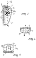
- Figure 1 is a side view of the photocell according to the invention;
- Figure 2 is a front view of the photocell;
- Figure 3 is a front view of the photocell, with the second half-shell omitted for the sake of clarity;
- Figure 4 is a sectional view, taken along the plane IV-IV of Figure 3;
- Figure 5 is a sectional view, taken along the plane V-V of Figure 3;
- Figure 6 is a sectional view, taken along the plane VI-VI of Figure 3.
-
- With reference to the above figures, the reference numeral 1 designates the photocell according to the present invention, which comprises a box-
like body 2 constituted by a first half-shell 3 and by a second half-shell 4 which can be mutually coupled by means of adapted screws 5 which can be associated, for example, frontally to the second half-shell 4; the stem of the screws can be associated at adapted first seats formed in a first half-shell 3. - The connection between the first half-shell and the second half-shell can furthermore be facilitated by the presence of adapted
tabs 7 which protrude therefrom along its perimeter and are substantially L-shaped, with a free end which can be inserted at complementarily shapedsecond seats 8 formed inside the second half-shell 4. - Suitable
electronic devices 9, such as for example electronic circuits, can be arranged within the first half-shell 3; a supportingwing 10 further protrudes toward the second half-shell 4 proximate to the upper end of the first half-shell 3 and supports a light source such as a projector element or a receiver element, designated by the reference numeral 11; the projector element can be constituted by an infrared light source, while the receiver element can be constituted by a receiver for an optical signal. - A substantially C-
shaped fork 13 is pivoted at right angles to thewing 10 and therefore at afirst axis 12; itssecond wings wing 10. - The light source 11 is rotatably associated between the
second wings second axis 15 which is perpendicular to thefirst axis 12. - Such rotation can be set selectively by the user, since means are provided which are suitable to discriminate the angular arrangement of the photocell; said means are constituted by suitable sets of
teeth 16 and complementary sets ofteeth 17 which protrude respectively from the lateral surfaces of the light source 11 and from the internal lateral surfaces of thesecond wings fork 13. - A
semitransparent region 18 is formed at the light source 11 at the second half-shell 4 and is adapted to allow the passage of the light beam. - It has thus been observed that the invention has achieved the intended aim and objects, a photocell having been provided which can be installed and therefore positioned without special care, since the light beam can be positioned rapidly and in an optimum manner by the operator by turning the
fork 13 in order to orientate it on a horizontal plane and by turning the light source 11 in order to orientate it on a vertical plane. - The presence of the complementary set of
teeth 17 and of the set ofteeth 16 further allows to stably select the arrangement of the light source 11 on the vertical plane, thus making the photocell free from malfunctions caused by vibrations and/or accidental impacts. - The resulting photocell is furthermore merely very compact as well as reliable and safe in use and has low associated costs.
- The materials and the dimensions that constitute the individual components of the photocell may of course be the most pertinent according to specific requirements.
- The disclosures in Italian Utility Model Application No. TV99U000019 from which this application claims priority are incorporated herein by reference.
- Where technical features mentioned in any claim are followed by reference signs, those reference signs have been included for the sole purpose of increasing the intelligibility of the claims and accordingly, such reference signs do not have any limiting effect on the interpretation of each element identified by way of example by such reference signs.
Claims (5)
- A photocell comprising a box-like body constituted by a first half shell for containing electronic devices and by a second half-shell which has a region which allows the passage of a light beam, characterized in that inside said first half-shell there is a support which is mounted on a first vertical axis and is meant to support a projector or receiver element which is in turn selectively mounted along a second axis which is perpendicular to said first axis.
- The photocell according to claim 1, characterized in that a supporting wing for said projector element or receiver element protrudes inside said first half shell, proximate to the upper end and toward said second half-shell.
- The photocell according to claim 2, characterized in that a substantially C-shaped fork is pivoted at right angles to said wing at a first axis which is perpendicular thereto, the wings of said fork being directed away from said supporting wing.
- The photocell according to claim 3, characterized in that said projector element or receiver element is rotatably associated between said wings of the fork and rotate at said second axis which is perpendicular to said first axis.
- The photocell according to claims 1 and 4, characterized in that the rotation on said second axis can be set selectively by the user, means being provided to discriminate the angular arrangement of said projector or receiver element, said means being constituted by sets of teeth and complementary sets of teeth which protrude respectively from lateral surfaces of said projector or receiver element and from internal lateral surfaces of said wings of the fork.
Applications Claiming Priority (2)
| Application Number | Priority Date | Filing Date | Title |
|---|---|---|---|
| ITTV990019 | 1999-04-16 | ||
| IT1999TV000019U IT248101Y1 (en) | 1999-04-16 | 1999-04-16 | PHOTOCELL STRUCTURE |
Publications (3)
| Publication Number | Publication Date |
|---|---|
| EP1045353A2 true EP1045353A2 (en) | 2000-10-18 |
| EP1045353A3 EP1045353A3 (en) | 2001-04-11 |
| EP1045353B1 EP1045353B1 (en) | 2004-06-16 |
Family
ID=11420560
Family Applications (1)
| Application Number | Title | Priority Date | Filing Date |
|---|---|---|---|
| EP00107054A Expired - Lifetime EP1045353B1 (en) | 1999-04-16 | 2000-04-04 | Photocell |
Country Status (4)
| Country | Link |
|---|---|
| EP (1) | EP1045353B1 (en) |
| AT (1) | ATE269568T1 (en) |
| DE (1) | DE60011505D1 (en) |
| IT (1) | IT248101Y1 (en) |
Cited By (4)
| Publication number | Priority date | Publication date | Assignee | Title |
|---|---|---|---|---|
| GB2390896A (en) * | 2002-04-11 | 2004-01-21 | Optex Co Ltd | Optical security sensor with manual tilt adjustment |
| FR2855296A1 (en) * | 2003-05-20 | 2004-11-26 | Christian Desliens | Photo-detection device e.g. photoelectric cell, for use in e.g. door opening device, has case fixed on support and with hollow profile, where case and support include complementary surfaces to rotate case following a semi-circular angle |
| EP1615053A1 (en) | 2004-07-07 | 2006-01-11 | Deitech S.r.l. | Radiation barrier element |
| WO2008031739A1 (en) * | 2006-09-15 | 2008-03-20 | Gi.Bi.Di. S.R.L. | Photocell with adjustable orientation particularly for optical barriers |
Citations (3)
| Publication number | Priority date | Publication date | Assignee | Title |
|---|---|---|---|---|
| US4282430A (en) * | 1978-06-19 | 1981-08-04 | Omron Tateisi Electronics Co. | Reflection-type photoelectric switching apparatus |
| US4811923A (en) * | 1987-02-25 | 1989-03-14 | Bron Elektronik Ag | Mount for photographic lighting equipment |
| US5245177A (en) * | 1991-10-24 | 1993-09-14 | Schiller Norman H | Electro-optical system for detecting the presence of an object within a predetermined detection system |
-
1999
- 1999-04-16 IT IT1999TV000019U patent/IT248101Y1/en active
-
2000
- 2000-04-04 EP EP00107054A patent/EP1045353B1/en not_active Expired - Lifetime
- 2000-04-04 AT AT00107054T patent/ATE269568T1/en not_active IP Right Cessation
- 2000-04-04 DE DE60011505T patent/DE60011505D1/en not_active Expired - Lifetime
Patent Citations (3)
| Publication number | Priority date | Publication date | Assignee | Title |
|---|---|---|---|---|
| US4282430A (en) * | 1978-06-19 | 1981-08-04 | Omron Tateisi Electronics Co. | Reflection-type photoelectric switching apparatus |
| US4811923A (en) * | 1987-02-25 | 1989-03-14 | Bron Elektronik Ag | Mount for photographic lighting equipment |
| US5245177A (en) * | 1991-10-24 | 1993-09-14 | Schiller Norman H | Electro-optical system for detecting the presence of an object within a predetermined detection system |
Cited By (6)
| Publication number | Priority date | Publication date | Assignee | Title |
|---|---|---|---|---|
| GB2390896A (en) * | 2002-04-11 | 2004-01-21 | Optex Co Ltd | Optical security sensor with manual tilt adjustment |
| GB2390896B (en) * | 2002-04-11 | 2005-09-14 | Optex Co Ltd | Anti-thief security sensor assembly |
| US6965315B2 (en) | 2002-04-11 | 2005-11-15 | Optex Co., Ltd. | Anti-thief security sensor assembly |
| FR2855296A1 (en) * | 2003-05-20 | 2004-11-26 | Christian Desliens | Photo-detection device e.g. photoelectric cell, for use in e.g. door opening device, has case fixed on support and with hollow profile, where case and support include complementary surfaces to rotate case following a semi-circular angle |
| EP1615053A1 (en) | 2004-07-07 | 2006-01-11 | Deitech S.r.l. | Radiation barrier element |
| WO2008031739A1 (en) * | 2006-09-15 | 2008-03-20 | Gi.Bi.Di. S.R.L. | Photocell with adjustable orientation particularly for optical barriers |
Also Published As
| Publication number | Publication date |
|---|---|
| ATE269568T1 (en) | 2004-07-15 |
| EP1045353B1 (en) | 2004-06-16 |
| EP1045353A3 (en) | 2001-04-11 |
| IT248101Y1 (en) | 2002-12-10 |
| ITTV990019V0 (en) | 1999-04-16 |
| DE60011505D1 (en) | 2004-07-22 |
| ITTV990019U1 (en) | 2000-10-16 |
Similar Documents
| Publication | Publication Date | Title |
|---|---|---|
| US4472908A (en) | Automatic gate | |
| EP1045353A2 (en) | Photocell | |
| JPH03171502A (en) | Projector type lighting device for vehicle | |
| JPH09277974A (en) | Headlamp for two-wheeler keeping irradiation range constant | |
| JP2001018718A (en) | Rear-view mirror | |
| JP2000123615A (en) | Sunlight radiating machine | |
| JPH08264016A (en) | Luminaire | |
| JPS6361019B2 (en) | ||
| JPH0330188Y2 (en) | ||
| JPH046083Y2 (en) | ||
| US4390254A (en) | Field stop operating mechanism for microscopes | |
| US20050264890A1 (en) | Rear view mirror shade | |
| JPS5916824Y2 (en) | Optical axis adjustment mechanism for optical detection devices, etc. | |
| JPS632202A (en) | Solar beam reflector | |
| JP3967777B2 (en) | Spotlight | |
| KR20170142437A (en) | Slope support apparatus for streetlight | |
| JP2863231B2 (en) | Heat ray sensing type human body detection sensor | |
| JPH0346401Y2 (en) | ||
| JPH049685Y2 (en) | ||
| JP2513516Y2 (en) | Vehicle headlights | |
| JPH07159157A (en) | Light wave range finder | |
| KR930000978A (en) | Solar tracking device | |
| JP2002158575A (en) | Attaching device for photoelectric switch | |
| JPS6128457Y2 (en) | ||
| SU1142746A1 (en) | Device for checking vehicle head-lights |
Legal Events
| Date | Code | Title | Description |
|---|---|---|---|
| PUAI | Public reference made under article 153(3) epc to a published international application that has entered the european phase |
Free format text: ORIGINAL CODE: 0009012 |
|
| AK | Designated contracting states |
Kind code of ref document: A2 Designated state(s): AT BE DE ES FR IT |
|
| AX | Request for extension of the european patent |
Free format text: AL;LT;LV;MK;RO;SI |
|
| PUAL | Search report despatched |
Free format text: ORIGINAL CODE: 0009013 |
|
| AK | Designated contracting states |
Kind code of ref document: A3 Designated state(s): AT BE CH CY DE DK ES FI FR GB GR IE IT LI LU MC NL PT SE |
|
| AX | Request for extension of the european patent |
Free format text: AL;LT;LV;MK;RO;SI |
|
| 17P | Request for examination filed |
Effective date: 20011001 |
|
| AKX | Designation fees paid |
Free format text: AT BE DE ES FR IT |
|
| 17Q | First examination report despatched |
Effective date: 20030611 |
|
| GRAP | Despatch of communication of intention to grant a patent |
Free format text: ORIGINAL CODE: EPIDOSNIGR1 |
|
| GRAS | Grant fee paid |
Free format text: ORIGINAL CODE: EPIDOSNIGR3 |
|
| GRAA | (expected) grant |
Free format text: ORIGINAL CODE: 0009210 |
|
| AK | Designated contracting states |
Kind code of ref document: B1 Designated state(s): AT BE DE ES FR IT |
|
| PG25 | Lapsed in a contracting state [announced via postgrant information from national office to epo] |
Ref country code: BE Free format text: LAPSE BECAUSE OF FAILURE TO SUBMIT A TRANSLATION OF THE DESCRIPTION OR TO PAY THE FEE WITHIN THE PRESCRIBED TIME-LIMIT Effective date: 20040616 Ref country code: AT Free format text: LAPSE BECAUSE OF FAILURE TO SUBMIT A TRANSLATION OF THE DESCRIPTION OR TO PAY THE FEE WITHIN THE PRESCRIBED TIME-LIMIT Effective date: 20040616 |
|
| REF | Corresponds to: |
Ref document number: 60011505 Country of ref document: DE Date of ref document: 20040722 Kind code of ref document: P |
|
| PG25 | Lapsed in a contracting state [announced via postgrant information from national office to epo] |
Ref country code: DE Free format text: LAPSE BECAUSE OF FAILURE TO SUBMIT A TRANSLATION OF THE DESCRIPTION OR TO PAY THE FEE WITHIN THE PRESCRIBED TIME-LIMIT Effective date: 20040917 |
|
| PG25 | Lapsed in a contracting state [announced via postgrant information from national office to epo] |
Ref country code: ES Free format text: LAPSE BECAUSE OF FAILURE TO SUBMIT A TRANSLATION OF THE DESCRIPTION OR TO PAY THE FEE WITHIN THE PRESCRIBED TIME-LIMIT Effective date: 20040927 |
|
| ET | Fr: translation filed | ||
| PLBE | No opposition filed within time limit |
Free format text: ORIGINAL CODE: 0009261 |
|
| STAA | Information on the status of an ep patent application or granted ep patent |
Free format text: STATUS: NO OPPOSITION FILED WITHIN TIME LIMIT |
|
| 26N | No opposition filed |
Effective date: 20050317 |
|
| PGFP | Annual fee paid to national office [announced via postgrant information from national office to epo] |
Ref country code: FR Payment date: 20080915 Year of fee payment: 9 |
|
| REG | Reference to a national code |
Ref country code: FR Ref legal event code: ST Effective date: 20081231 |
|
| PG25 | Lapsed in a contracting state [announced via postgrant information from national office to epo] |
Ref country code: FR Free format text: LAPSE BECAUSE OF NON-PAYMENT OF DUE FEES Effective date: 20080430 |
|
| PGFP | Annual fee paid to national office [announced via postgrant information from national office to epo] |
Ref country code: IT Payment date: 20090423 Year of fee payment: 10 |
|
| PG25 | Lapsed in a contracting state [announced via postgrant information from national office to epo] |
Ref country code: IT Free format text: LAPSE BECAUSE OF NON-PAYMENT OF DUE FEES Effective date: 20100404 |
|
| PG25 | Lapsed in a contracting state [announced via postgrant information from national office to epo] |
Ref country code: FR Free format text: LAPSE BECAUSE OF NON-PAYMENT OF DUE FEES Effective date: 20090430 |