EP1045344A2 - Simultationsverfahren zur Realzeit-Darstellung einer Umgebung - Google Patents
Simultationsverfahren zur Realzeit-Darstellung einer Umgebung Download PDFInfo
- Publication number
- EP1045344A2 EP1045344A2 EP00108130A EP00108130A EP1045344A2 EP 1045344 A2 EP1045344 A2 EP 1045344A2 EP 00108130 A EP00108130 A EP 00108130A EP 00108130 A EP00108130 A EP 00108130A EP 1045344 A2 EP1045344 A2 EP 1045344A2
- Authority
- EP
- European Patent Office
- Prior art keywords
- environment
- objects
- virtual
- point
- representation
- Prior art date
- Legal status (The legal status is an assumption and is not a legal conclusion. Google has not performed a legal analysis and makes no representation as to the accuracy of the status listed.)
- Withdrawn
Links
Images
Classifications
-
- G—PHYSICS
- G06—COMPUTING OR CALCULATING; COUNTING
- G06T—IMAGE DATA PROCESSING OR GENERATION, IN GENERAL
- G06T15/00—Three-dimensional [3D] image rendering
- G06T15/10—Geometric effects
- G06T15/40—Hidden part removal
- G06T15/405—Hidden part removal using Z-buffer
Definitions
- the invention relates to a simulation method for real-time representation of changes in real environment.
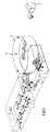
- the Simulation room 1 shows a training device for air traffic controllers with a simulation room 1.
- the Simulation room 1 has a cylindrical wall 3, which at the same time the simulation room 1 in Limited circumferential direction.
- Air traffic controllers are in the area of the spatial center of simulation room 1.
- Means an image generator 5 and at least one projector (not shown) become visual Representations of a simulated environment are projected onto the cylindrical wall 3, the simulated environment preferably over the entire inner surface of the cylindrical wall 3 extends.
- each air traffic controller located in the simulation room 1 has a representation the simulated outside world in the circumferential direction over the entire cylindrical wall 3, i.e. out View of an air traffic controller up to an angular range of 360 °.
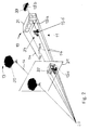
- Each texture preferably comprises an object or one Part of the environment 11, e.g. a house, planes, vehicles, plantings, lanes, Cultivation or building properties. 2 are exemplary of the components of the Environment 11 a tree 30, a house 31, a car 33 and a bicycle 34 and some examples Projection lines 14 starting from an eye point 20 are shown.
- Projection lines 14 starting from an eye point 20 are shown.
- FIG. 2 also shows the object points 15b of the car 33 located on a projection line 14a seen from the viewpoint 20 behind the house 31, 15a of the house 31 and 15d of the bicycle 34 located in front of the house 31 as seen from the eye point 20 drawn. Since the mentioned object points 15a, 15b, 15d on one and the same Projection line 14 are located, these points come separately at the same point 15c on a virtual imaging level 21 for display.
- the textures 13 are based on an eye point 20 corresponding projection lines 14 projected onto the virtual imaging plane 21 (FIG. 2). This process takes place in real time, since the environment 11 is time-varying and in the simulation must be presented in real time.
- This projection of the textures 13 onto the virtual one Imaging plane 21 with respect to the eye point 20 takes place in a data processing system, for example in the image generator 5, which is assigned to the simulation room 1.
- the representation on the virtual Imaging plane 21 on the real imaging surface e.g. on a monitor or the cylindrical Transfer wall 3.
- the virtual environment 11 is implemented on a real display surface in an initial step e.g. a virtual environment 11 on the virtual mapping level 21 the optical laws with respect to the eye point 20 projected.
- the eye point 20 corresponds to a fictitious or the real location of a viewer, e.g. the location the air traffic controller in the simulation room 1.
- the one in the initial state on the virtual imaging level Environment 21 shown thus corresponds to the initial state of the simulated environment.
- the Environment 11 changes automatically, or due to the action of random generators or due to manual or automatic inputs or changes to a real or virtual environment 11 over time. To these temporal changes of the environment 11 on the To transmit virtual imaging level 21, the imaging of objects or Object points of the environment 11 are calculated in each iteration cut.
- Projections on the virtual imaging level 21 are based on the temporal To represent changes in the virtual environment 11 for the respective calculation cycle.
- the Previous iteration cycles have been calculated and displayed on the Figure 21 brought representations that are related to the current Iteration cut have not changed in the current iteration cut calculated.
- the image generator 5 stores for everyone from a predetermined rasterization or Resolutions resulting point on the virtual imaging plane 21, the distance of the corresponding point in the corresponding 3D texture 13 in the environment 11 from Eye point 20.
- the properties compared include, in particular, the distance of the respective point an object of the virtual environment 11.
- a point 15d of an object replaces the virtual environment 11 another point 15a, 15b of the same or another object of the virtual environment from a previous cycle if the first point is a closer distance to the virtual imaging level 21.
- the imaging points on imaging level 21 that are opposite each other are examined change a previous cycle. This is done immediately in a calculation cycle from the imaging point 15c of an object point 15a on the imaging plane 21 assumed that was already shown in the previous iteration cycle is.
- the advantage of the method according to the invention lies in the fact that not every one to be represented Object of the environment 11 for mapping on the virtual mapping level 21 in each Calculation cycle must be calculated. Instead, there will be a significant reduction in Computational effort achieved, since only a calculation from the previous to the mapping point changing the current calculation cycle for the representation on the virtual mapping level 21 must be calculated.
- an object for example a House 31 projected onto the virtual mapping level 21.
- the eye point 20 results a two-dimensional representation 32 of the House 31.
- a car 33 located in the environment 11 is placed on the virtual one Imaging plane 21 only shown when the car 33 is not seen from the eye point 20 is covered by house 31.
- the car 33 is covered by the house 31 and is thus not shown on the image plane 21.
- a complete calculation of the entire environment 11 in takes place only once in relation to the virtual imaging level 21.
- Moving parts such as the car 33, only then have Influence on the virtual imaging level 21 when the individual object points of the aircraft 33 from the point of view of eye 20 not from another object of the virtual environment 11, e.g. be covered by house 31. So only the points of the in the environment 11 moving objects or textures 13 considered and these points with the corresponding, i.e. seen from eye point 20, lying on the same projection line Point of another object of the virtual environment 11 compared. Thereby every object point basically a current depth information is attached. The depth information and other properties of the points of different objects lying on a projection line or textures or different parts of the same are then compared. Then it arrives another object point or a property of the same for display on the virtual Imaging plane 21, if this or this is a smaller depth or a smaller distance from of the virtual imaging plane 21 along the associated projection line.
Landscapes
- Physics & Mathematics (AREA)
- Engineering & Computer Science (AREA)
- Geometry (AREA)
- Computer Graphics (AREA)
- General Physics & Mathematics (AREA)
- Theoretical Computer Science (AREA)
- Processing Or Creating Images (AREA)
- Image Generation (AREA)
Abstract
Description
- Fig. 1
- eine schematische Darstellung eines Anwendungsbeispiels des erfindungsgemäßen Verfahrens bzw. der erfindungsgemäßen Vorrichtung, das sich auf eine Trainingseinrichtung für Fluglotsen mit einem Bildschirm-Raum bezieht, in dem die Verkehrs-Situation einer zeitveränderlichen realen oder fiktiven Umgebung in Realzeit simuliert wird, und
- Fig. 2
- die schematische Darstellung der Abbildung von Gegenständen einer virtuellen dreidimensionalen Welt auf eine virtuelle Abbildungsebene, die als Basis für die Darstellung der darauf abgebildeten Gegenstände auf einem Monitor oder einer Leinwand dient.
Claims (1)
- Simulationsverfahren zur Darstellung einer Umwelt (11) mit Objekten (15, 31, 33, 34) auf eine virtuelle Abbildungsebene (21) in Realzeit zur Erzeugung einer zweidimensionalen Darstellung der Umwelt (11), mit den folgenden Schritten:Berechnung der Abbildung und Darstellung der Objekte (30, 31) der Umwelt (11) auf der virtuellen Abbildungsebene (21) und Speichern der jeweiligen Entfernungen der zugehörigen Objektpunkte zum Augenpunkt, und in den nachfolgenden Iterationsschritten:Ermittlung derjenigen Objekte, deren Entfernung zum Augenpunkt (20) sich in bezug auf den jeweils vorangegangenen Iterationsschnitt geändert haben, und für diejenigen Bildpunkte, die durch die Veränderung eines Objektes betroffen sind, Vergleich der Entfernungen der Objektpunkte der veränderten Objekte mit den Entfernungen, die für diesen Bildpunkt gespeichert sind,Berechnung der Abbildung und Darstellung derjenigen Objektpunkte (15d), deren Objekte sich im Vergleich zum vorangegangenen Iterationsschnitt verändert haben und die näher als der im vorangegangenen Iterationsschritt dargestellte Objektpunkt (15a) am Augenpunkt (20) liegen,sowie Darstellung der Objektpunkte von Objekten, die sich im Vergleich zum vorangegangenen Iterationsschritt nicht verändert haben, aufgrund der in einem vorangegangenen berechneten Abbildung.
Applications Claiming Priority (2)
| Application Number | Priority Date | Filing Date | Title |
|---|---|---|---|
| DE19917012 | 1999-04-15 | ||
| DE1999117012 DE19917012A1 (de) | 1999-04-15 | 1999-04-15 | Simulationsverfahren zur Realzeit-Darstellung einer Umgebung |
Publications (2)
| Publication Number | Publication Date |
|---|---|
| EP1045344A2 true EP1045344A2 (de) | 2000-10-18 |
| EP1045344A3 EP1045344A3 (de) | 2002-08-21 |
Family
ID=7904656
Family Applications (1)
| Application Number | Title | Priority Date | Filing Date |
|---|---|---|---|
| EP00108130A Withdrawn EP1045344A3 (de) | 1999-04-15 | 2000-04-13 | Simultationsverfahren zur Realzeit-Darstellung einer Umgebung |
Country Status (2)
| Country | Link |
|---|---|
| EP (1) | EP1045344A3 (de) |
| DE (1) | DE19917012A1 (de) |
Family Cites Families (3)
| Publication number | Priority date | Publication date | Assignee | Title |
|---|---|---|---|---|
| DE3035213C2 (de) * | 1980-09-18 | 1983-11-03 | Messerschmitt-Bölkow-Blohm GmbH, 8000 München | Verfahren zur Gewinnung und Wiedergabe von Geländebildern für Sichtsimulatoren |
| GB9406511D0 (en) * | 1994-03-31 | 1994-05-25 | Argonaut Software Limited | Z-buffering in 3-d computer graphics |
| AU722393B2 (en) * | 1996-11-07 | 2000-08-03 | Broderbund Software, Inc. | System for adaptive animation compression |
-
1999
- 1999-04-15 DE DE1999117012 patent/DE19917012A1/de not_active Ceased
-
2000
- 2000-04-13 EP EP00108130A patent/EP1045344A3/de not_active Withdrawn
Also Published As
| Publication number | Publication date |
|---|---|
| DE19917012A1 (de) | 2000-10-26 |
| EP1045344A3 (de) | 2002-08-21 |
Similar Documents
| Publication | Publication Date | Title |
|---|---|---|
| DE69126611T2 (de) | Bilderzeugungsgerät | |
| DE3650129T2 (de) | Verfahren zur Kantenglättung für Rechnerbilderzeugungssystem. | |
| DE3854543T2 (de) | Prioritätsverwaltung eines Tiefendatenpuffers für Echtzeitrechnersysteme zur Bilderzeugung. | |
| DE3854223T2 (de) | Erzeugung und Anzeige von Rechnergraphiken. | |
| DE3688565T2 (de) | Verfahren und System zur Bildveränderung. | |
| DE69129427T2 (de) | Pixelinterpolation im Perspektivraum | |
| DE4211385A1 (de) | Daten-projektionssystem | |
| DE112012006746T5 (de) | Kartenanzeigevorrichtung | |
| EP2206089A1 (de) | Verfahren und vorrichtung zum darstellen eines virtuellen objekts in einer realen umgebung | |
| DE102019005885A1 (de) | Umgebungskartengenerierung und Lochfüllung | |
| DE19549096A1 (de) | Simulationsvorrichtung und -verfahren | |
| EP3571091B1 (de) | Verfahren und vorrichtung zum darstellen einer umgebung eines fahrzeuges | |
| DE102016124978A1 (de) | Virtuelle Repräsentation einer Umgebung eines Kraftfahrzeugs in einem Fahrerassistenzsystem mit mehreren Projektionsflächen | |
| DE102008036219A1 (de) | Verfahren zur Erkennung von Objekten im Umfeld eines Fahrzeugs | |
| EP2893510B1 (de) | Verfahren und bildverarbeitungsanlage zum entfernen eines visuellen objektes aus einem bild | |
| DE4113992A1 (de) | Verfahren zur automatischen dreidimensionalen ueberwachung von gefahrenraeumen | |
| DE102004040372B4 (de) | Verfahren und Vorrichtung zur Darstellung einer dreidimensionalen Topographie | |
| DE60026853T2 (de) | Verfahren und gerät zum berechnen eines graphischen bildes einer texturierten oberfläche | |
| DE102011082881A1 (de) | Darstellung der Umgebung eines Kraftfahrzeugs in einer bestimmten Ansicht unter Verwendung räumlicher Information | |
| DE69416758T2 (de) | Gerät und Verfahren zur Bildverarbeitung | |
| EP3465608B1 (de) | Verfahren und vorrichtung zum bestimmen eines übergangs zwischen zwei anzeigebildern, und fahrzeug | |
| DE19917012A1 (de) | Simulationsverfahren zur Realzeit-Darstellung einer Umgebung | |
| DE102023101672A1 (de) | Verfahren und Vorrichtung zur automatischen Lokalisation von zur Entnahme geeigneten Objekten aus einer Objekt-Anhäufung | |
| DE69233060T2 (de) | System zur Anzeige von räumlichen Einschnitten für Festkörpermodellflächen | |
| DE102007056835A1 (de) | Bildverarbeitunsmodul zur Schätzung einer Objektposition eines Überwachungsobjekts, Verfahren zur Bestimmung einer Objektposition eines Überwachungsobjekts sowie Computerprogramm |
Legal Events
| Date | Code | Title | Description |
|---|---|---|---|
| PUAI | Public reference made under article 153(3) epc to a published international application that has entered the european phase |
Free format text: ORIGINAL CODE: 0009012 |
|
| AK | Designated contracting states |
Kind code of ref document: A2 Designated state(s): AT BE CH CY DE DK ES FI FR GB GR IE IT LI LU MC NL PT SE |
|
| AX | Request for extension of the european patent |
Free format text: AL;LT;LV;MK;RO;SI |
|
| PUAL | Search report despatched |
Free format text: ORIGINAL CODE: 0009013 |
|
| AK | Designated contracting states |
Kind code of ref document: A3 Designated state(s): AT BE CH CY DE DK ES FI FR GB GR IE IT LI LU MC NL PT SE |
|
| AX | Request for extension of the european patent |
Free format text: AL;LT;LV;MK;RO;SI |
|
| RIC1 | Information provided on ipc code assigned before grant |
Free format text: 7G 06T 15/70 A, 7G 06T 15/40 B |
|
| STAA | Information on the status of an ep patent application or granted ep patent |
Free format text: STATUS: THE APPLICATION HAS BEEN WITHDRAWN |
|
| 18W | Application withdrawn |
Withdrawal date: 20020824 |