EP1045131A2 - Einrichtung zur Versorgung einer Brennkraftmaschine eines Kraftfahrzeuges mit Kraftstoff - Google Patents
Einrichtung zur Versorgung einer Brennkraftmaschine eines Kraftfahrzeuges mit Kraftstoff Download PDFInfo
- Publication number
- EP1045131A2 EP1045131A2 EP00104765A EP00104765A EP1045131A2 EP 1045131 A2 EP1045131 A2 EP 1045131A2 EP 00104765 A EP00104765 A EP 00104765A EP 00104765 A EP00104765 A EP 00104765A EP 1045131 A2 EP1045131 A2 EP 1045131A2
- Authority
- EP
- European Patent Office
- Prior art keywords
- return line
- cooling
- fuel
- line
- ventilation duct
- Prior art date
- Legal status (The legal status is an assumption and is not a legal conclusion. Google has not performed a legal analysis and makes no representation as to the accuracy of the status listed.)
- Granted
Links
Images
Classifications
-
- F—MECHANICAL ENGINEERING; LIGHTING; HEATING; WEAPONS; BLASTING
- F02—COMBUSTION ENGINES; HOT-GAS OR COMBUSTION-PRODUCT ENGINE PLANTS
- F02M—SUPPLYING COMBUSTION ENGINES IN GENERAL WITH COMBUSTIBLE MIXTURES OR CONSTITUENTS THEREOF
- F02M37/00—Apparatus or systems for feeding liquid fuel from storage containers to carburettors or fuel-injection apparatus; Arrangements for purifying liquid fuel specially adapted for, or arranged on, internal-combustion engines
-
- F—MECHANICAL ENGINEERING; LIGHTING; HEATING; WEAPONS; BLASTING
- F02—COMBUSTION ENGINES; HOT-GAS OR COMBUSTION-PRODUCT ENGINE PLANTS
- F02M—SUPPLYING COMBUSTION ENGINES IN GENERAL WITH COMBUSTIBLE MIXTURES OR CONSTITUENTS THEREOF
- F02M31/00—Apparatus for thermally treating combustion-air, fuel, or fuel-air mixture
- F02M31/20—Apparatus for thermally treating combustion-air, fuel, or fuel-air mixture for cooling
-
- B—PERFORMING OPERATIONS; TRANSPORTING
- B60—VEHICLES IN GENERAL
- B60K—ARRANGEMENT OR MOUNTING OF PROPULSION UNITS OR OF TRANSMISSIONS IN VEHICLES; ARRANGEMENT OR MOUNTING OF PLURAL DIVERSE PRIME-MOVERS IN VEHICLES; AUXILIARY DRIVES FOR VEHICLES; INSTRUMENTATION OR DASHBOARDS FOR VEHICLES; ARRANGEMENTS IN CONNECTION WITH COOLING, AIR INTAKE, GAS EXHAUST OR FUEL SUPPLY OF PROPULSION UNITS IN VEHICLES
- B60K15/00—Arrangement in connection with fuel supply of combustion engines or other fuel consuming energy converters, e.g. fuel cells; Mounting or construction of fuel tanks
- B60K15/01—Arrangement of fuel conduits
-
- B—PERFORMING OPERATIONS; TRANSPORTING
- B60—VEHICLES IN GENERAL
- B60K—ARRANGEMENT OR MOUNTING OF PROPULSION UNITS OR OF TRANSMISSIONS IN VEHICLES; ARRANGEMENT OR MOUNTING OF PLURAL DIVERSE PRIME-MOVERS IN VEHICLES; AUXILIARY DRIVES FOR VEHICLES; INSTRUMENTATION OR DASHBOARDS FOR VEHICLES; ARRANGEMENTS IN CONNECTION WITH COOLING, AIR INTAKE, GAS EXHAUST OR FUEL SUPPLY OF PROPULSION UNITS IN VEHICLES
- B60K15/00—Arrangement in connection with fuel supply of combustion engines or other fuel consuming energy converters, e.g. fuel cells; Mounting or construction of fuel tanks
- B60K15/03—Fuel tanks
- B60K2015/03328—Arrangements or special measures related to fuel tanks or fuel handling
- B60K2015/03414—Arrangements or special measures related to fuel tanks or fuel handling associated with the fuel tank for cooling heated fuel
-
- Y—GENERAL TAGGING OF NEW TECHNOLOGICAL DEVELOPMENTS; GENERAL TAGGING OF CROSS-SECTIONAL TECHNOLOGIES SPANNING OVER SEVERAL SECTIONS OF THE IPC; TECHNICAL SUBJECTS COVERED BY FORMER USPC CROSS-REFERENCE ART COLLECTIONS [XRACs] AND DIGESTS
- Y02—TECHNOLOGIES OR APPLICATIONS FOR MITIGATION OR ADAPTATION AGAINST CLIMATE CHANGE
- Y02T—CLIMATE CHANGE MITIGATION TECHNOLOGIES RELATED TO TRANSPORTATION
- Y02T10/00—Road transport of goods or passengers
- Y02T10/10—Internal combustion engine [ICE] based vehicles
- Y02T10/12—Improving ICE efficiencies
-
- Y—GENERAL TAGGING OF NEW TECHNOLOGICAL DEVELOPMENTS; GENERAL TAGGING OF CROSS-SECTIONAL TECHNOLOGIES SPANNING OVER SEVERAL SECTIONS OF THE IPC; TECHNICAL SUBJECTS COVERED BY FORMER USPC CROSS-REFERENCE ART COLLECTIONS [XRACs] AND DIGESTS
- Y10—TECHNICAL SUBJECTS COVERED BY FORMER USPC
- Y10T—TECHNICAL SUBJECTS COVERED BY FORMER US CLASSIFICATION
- Y10T137/00—Fluid handling
- Y10T137/6416—With heating or cooling of the system
- Y10T137/6525—Air heated or cooled [fan, fins, or channels]
Definitions
- the invention relates to a device for supply an internal combustion engine of a motor vehicle with fuel with one from a fuel tank to the Internal combustion engine leading flow line and with a Return line for returning the fuel to the Fuel tank and with a cooling device for cooling of the fuel returned to the fuel tank.
- the cooling device has here one installed in the return line, the headwind the radiator exposed to the motor vehicle.
- the cooling of the Fuel is used to measure the temperature in the fuel tank to keep below a planned value.
- the maximal Temperature that does not exceed in the fuel tank is essentially dependent on the material of the fuel tank and is today's Plastic fuel tanks around 70 ° C.
- the cooling of the fuel in the return line is for example in systems referred to as common rail of internal combustion engines is required, since this is about the return line returned fuel from the Internal combustion engine is heated particularly strongly.
- a disadvantage of the known device is that it structurally due to the radiator to be fixed in the wind very complex and costly to manufacture is.
- the invention is based on the problem of a device of the type mentioned in such a way that they structurally simple and inexpensive is to be produced.
- This design allows the fuel to heat through the Deliver the wall of the return line. This is for the cooling of the fuel does not require any effort in the return line components to be assembled required.
- the device according to the invention is therefore particularly simple constructed and can be produced inexpensively. Since the Fuel within the return line has a large temperature difference towards the environment is sufficient as cooling medium usually ambient air of the motor vehicle.
- the medium that cools the fuel in the return line could, for example, as in the known device Driving wind of the motor vehicle. Here is, however especially when driving the motor vehicle uphill or in Traffic congestion sufficient cooling of the fuel not guaranteed.
- the fuel in the return line can be according to an advantageous development the invention reliably to an intended temperature level cool when the cooler on the air fan or a fan along the return line Has suction unit for combustion air.
- the cooling the return line with the intake of the internal combustion engine Combustion air also has the advantage that Leaks or by permeation from the invention Device escaping fuel from the internal combustion engine is fed.
- the fuel in the return line is according to another advantageous development of the invention particularly strongly cooled, if the cooling device Ventilation duct for receiving the return line and for Guiding the cooling air along the return line having.
- the cooling device needs Further development of the invention no additional mounting blower if the ventilation duct up to a Suction side of a cooling fan of a liquid cooling system the internal combustion engine is guided.
- the device according to the invention is particularly simple mount in the motor vehicle if the flow line is arranged within the ventilation duct.
- the supply line and the return line first connect with each other and then together fasten in the ventilation duct. Because the in the lead pipe delivered fuel a lower temperature has than that existing in the return line, can this design does not unnecessarily heat the fuel returned to the fuel tank.
- the fuel tank can be advantageous according to another Development of the invention simply on one maintain the intended temperature level when the ventilation duct at least a portion of the fuel tank encased at a distance. It is sufficient if the floor area of the fuel tank is covered, in particular when the fuel tank is almost empty, that of the Return line fuel returned a large Influences the temperature in the fuel tank.
- the return line has another advantageous one Development of the invention a particularly large heat emitting Area when cooling elements on the return line are arranged.
- the device according to the invention is constructive particularly easy if the flow line from one Material with a high thermal conductivity is made and when the return line and the flow line come together issue. Because the fuel in the return line a higher temperature and a smaller volume flow has than in the flow line, he is thereby cooled particularly reliably.
- This design can be used alone or together with the one on the return line along cooling air the temperature in the fuel tank keep low. Another advantage of this Design is that the engine at preheated fuel after a cold start.
- the assembly of the flow line and the return line in the Motor vehicle is designed according to another advantageous Development of the invention is particularly simple, if the supply line and the return line are one piece with a common partition with a high Have thermal conductivity.
- the device according to the invention requires a special one little construction when the return line and the flow line are twisted together.
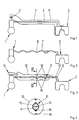
- FIG. 1 shows schematically a diesel engine Internal combustion engine 1 of a motor vehicle and a fuel tank 2 designed as a saddle tank.
- the internal combustion engine 1 is connected via a flow line 3 supplied with fuel from the fuel tank 2. Excess, very strong from the internal combustion engine 1 heated fuel is in via a return line 4 in returned the fuel tank 2.
- the lead pipe 3 and the return line 4 are in a common, themselves from the internal combustion engine 1 to the fuel tank 2 extending ventilation duct 5 arranged.
- Ventilation duct 5 At the end of the internal combustion engine 1 Ventilation duct 5, a blower 6 is arranged. The blower 6 sucks in air through ventilation duct 5.
- Ventilation duct 5 At the end of the internal combustion engine 1 Ventilation duct 5, a blower 6 is arranged. The blower 6 sucks in air through ventilation duct 5.
- For clarification are flow directions of in the drawing Air and fuel marked with arrows.
- the Return line 4 is made of a material with a good Thermal conductivity manufactured.
- the hot one, in the return line 4 flowing fuel gives much of it Heat to the air flowing in the ventilation duct 5.
- the blower 6 and the ventilation duct 5 can Temperature of the recycled into the fuel tank 2 Fuel reliably below an intended one Maintain a value of 70 ° C, for example.
- the blower 6 can be a separate blower or a blower for liquid cooling, not shown the engine 1 act.
- the fuel tank 2 is only with that area in the Ventilation duct 5 is arranged, in which the return line 4th flows. This area is defined by that of the internal combustion engine 1 recirculated fuel heated particularly strongly.
- the fan 6 can also be air convey into ventilation duct 5. This builds up a pressure stabilizing this in the ventilation duct 5 on.
- FIG. 2 shows schematically a further embodiment the device according to the invention, in which a flow line 7 and a return line 8 twisted together are.
- the flow line 7 and the return line 8 are made of a heat-conducting material. Since in the feed line 7 compared to the return line 8 larger volume flow at a lower one Temperature is promoted, heat from the return line 8 simply flow over to the supply line 7. Flow line 7 and return line 8 thus form one Counterflow heat exchanger.
- FIG. 3 shows schematically a further embodiment the device according to the invention, in which a flow line 9 and a return line 10 a common Have section 11. Furthermore, the supply line 9 and the return line 10 in a common ventilation duct 12 arranged.
- the ventilation duct 12 is with one end to an intake unit 13 of the internal combustion engine 1 connected. On the common section 11 are Cooling elements 15 arranged.
- the ventilation duct 12 supports its inside guide elements 16 for directing the air.
- Figure 4 shows this in a greatly enlarged manner in the ventilation duct 12 arranged common section 11 of the flow line 9 and the return line 10.
- the partition 14 is made of a material with high thermal conductivity, so that heat from the return line 10 to the Flow line 9 and to those in the ventilation duct 12 flowing air can flow over.
Landscapes
- Engineering & Computer Science (AREA)
- Chemical & Material Sciences (AREA)
- Combustion & Propulsion (AREA)
- Mechanical Engineering (AREA)
- General Engineering & Computer Science (AREA)
- Life Sciences & Earth Sciences (AREA)
- Sustainable Development (AREA)
- Sustainable Energy (AREA)
- Transportation (AREA)
- Cooling, Air Intake And Gas Exhaust, And Fuel Tank Arrangements In Propulsion Units (AREA)
Abstract
Description
- Fig.1
- eine schematische Darstellung einer erfindungsgemäßen Einrichtung mit einem Lüftungskanal,
- Fig.2
- schematisch eine weitere Ausführungsform der erfindungsgemäßen Einrichtung,
- Fig.3
- eine weitere Ausführungsform der erfindungsgemäßen Einrichtung in schematischer Darstellung,
- Fig.4
- eine Schnittdarstellung durch ein gemeinsames Teilstück von Vorlauf- und Rücklaufleitung der Figur 3 entlang der Linie IV- IV.
Claims (11)
- Einrichtung zur Versorgung einer Brennkraftmaschine eines Kraftfahrzeuges mit Kraftstoff mit einer von einem Kraftstoffbehälter zu der Brennkraftmaschine führenden Vorlaufleitung und mit einer Rücklaufleitung zur Rückführung des Kraftstoffs in den Kraftstoffbehälter und mit einer Kühleinrichtung zur Kühlung des in den Kraftstoffbehälter zurückgeführten Kraftstoffs, dadurch gekennzeichnet, daß die Rücklaufleitung (4, 8, 10) aus einem Material mit einer hohen Wärmeleitfähigkeit gefertigt ist und daß die Kühleinrichtung Mittel zur Führung eines kühlenden Mediums entlang zumindest eines Teilstücks der Rücklaufleitung (4, 8, 10) aufweist.
- Einrichtung nach Anspruch 1, dadurch gekennzeichnet, daß die Kühleinrichtung ein die Luft entlang der Rücklaufleitung (4, 10) förderndes Gebläse (6) oder eine Ansaugeinheit (13) für Verbrennungsluft aufweist.
- Einrichtung nach Anspruch 1 oder 2, dadurch gekennzeichnet, daß die Kühleinrichtung einen Lüftungskanal (5, 12) zur Aufnahme der Rücklaufleitung (4, 10) und zur Führung der kühlenden Luft entlang der Rücklaufleitung (4, 10) hat.
- Einrichtung nach zumindest einem der vorhergehenden Ansprüche, dadurch gekennzeichnet, daß der Lüftungskanal (5, 12) bis zu einer Saugseite eines Kühlgebläses einer Flüssigkeitskühlung der Brennkraftmaschine (1) geführt ist.
- Einrichtung nach zumindest einem der vorhergehenden Ansprüche, dadurch gekennzeichnet, daß die Vorlaufleitung (3, 9) innerhalb des Lüftungskanals (5, 12) angeordnet ist.
- Einrichtung nach zumindest einem der vorhergehenden Ansprüche, dadurch gekennzeichnet, daß der Lüftungskanal (3) zumindest einen Teilbereich des Kraftstoffbehälters (2) mit Abstand ummantelt.
- Einrichtung nach zumindest einem der vorhergehenden Ansprüche, dadurch gekennzeichnet, daß auf der Rücklaufleitung (10) Kühlelemente (15) angeordnet sind.
- Einrichtung nach zumindest einem der vorhergehenden Ansprüche, gekennzeichnet durch Leitelemente (16) zur Führung kühlender Luft auf die Rücklaufleitung (10).
- Einrichtung nach zumindest einem der vorhergehenden Ansprüche, dadurch gekennzeichnet, daß die Vorlaufleitung (7, 9) aus einem Material mit einer hohen Wärmeleitfähigkeit gefertigt ist und daß die Rücklaufleitung (8, 10) und die Vorlaufleitung (7, 9) aneinander anliegen.
- Einrichtung nach zumindest einem der vorhergehenden Ansprüche, dadurch gekennzeichnet, daß die Vorlaufleitung (9) und die Rücklaufleitung (10) ein Teilstück (11) mit einer gemeinsamen Trennwand (14) mit einer hohen Wärmeleitfähigkeit aufweisen.
- Einrichtung nach zumindest einem der vorhergehenden Ansprüche, dadurch gekennzeichnet, daß die Rücklaufleitung (8) und die Vorlaufleitung (7) miteinander verdrillt sind.
Applications Claiming Priority (2)
| Application Number | Priority Date | Filing Date | Title |
|---|---|---|---|
| DE19916530 | 1999-04-13 | ||
| DE1999116530 DE19916530A1 (de) | 1999-04-13 | 1999-04-13 | Einrichtung zur Versorgung einer Brennkraftmaschine eines Kraftfahrzeuges mit Kraftstoff |
Publications (3)
| Publication Number | Publication Date |
|---|---|
| EP1045131A2 true EP1045131A2 (de) | 2000-10-18 |
| EP1045131A3 EP1045131A3 (de) | 2001-03-07 |
| EP1045131B1 EP1045131B1 (de) | 2005-01-19 |
Family
ID=7904324
Family Applications (1)
| Application Number | Title | Priority Date | Filing Date |
|---|---|---|---|
| EP20000104765 Expired - Lifetime EP1045131B1 (de) | 1999-04-13 | 2000-03-04 | Einrichtung zur Versorgung einer Brennkraftmaschine eines Kraftfahrzeuges mit Kraftstoff |
Country Status (6)
| Country | Link |
|---|---|
| US (1) | US6250328B1 (de) |
| EP (1) | EP1045131B1 (de) |
| KR (1) | KR20000071661A (de) |
| BR (1) | BR0001588A (de) |
| DE (2) | DE19916530A1 (de) |
| ES (1) | ES2235701T3 (de) |
Cited By (1)
| Publication number | Priority date | Publication date | Assignee | Title |
|---|---|---|---|---|
| EP3330116A1 (de) * | 2016-12-02 | 2018-06-06 | Eberspächer Climate Control Systems GmbH & Co. KG. | Fahrzeug |
Families Citing this family (5)
| Publication number | Priority date | Publication date | Assignee | Title |
|---|---|---|---|---|
| FR2880386A1 (fr) * | 2004-12-30 | 2006-07-07 | Renault Sas | Agencement pour le montage d'un refroidisseur de carburant sur la caisse d'un vehicule |
| DE102008013887B4 (de) * | 2008-03-12 | 2017-04-06 | Bayerische Motoren Werke Aktiengesellschaft | Anordnung einer Rücklaufleitung in einem Kraftstofftank eines Kraftfahrzeugs |
| KR101105206B1 (ko) * | 2008-12-22 | 2012-01-13 | 르노삼성자동차 주식회사 | Lpli 차량의 공조장치 |
| GB201218815D0 (en) * | 2012-10-19 | 2012-12-05 | Airbus Operations Ltd | Aircraft fuel system with fuel return from engine |
| US9784226B2 (en) | 2013-02-07 | 2017-10-10 | Ford Global Technologies, Llc | Vehicle fuel delivery system |
Family Cites Families (23)
| Publication number | Priority date | Publication date | Assignee | Title |
|---|---|---|---|---|
| US4072138A (en) * | 1976-07-22 | 1978-02-07 | Hawkins Enterprises, Inc. | Fuel system |
| DE2841557A1 (de) * | 1978-09-23 | 1980-04-03 | Daimler Benz Ag | Kraftstoffsystem fuer ein kraftfahrzeug |
| DE3107141A1 (de) * | 1981-02-26 | 1982-09-09 | Kienzle Apparate Gmbh, 7730 Villingen-Schwenningen | Anordnung zum kuehlen des kraftstoffs in einem betriebssystem eines dieselmotors mit einem geschlossenen einspritzkreislauf |
| JPS59155564A (ja) * | 1983-02-24 | 1984-09-04 | Toyota Motor Corp | 燃料噴射式エンジンの燃料分配管 |
| US4768492A (en) * | 1987-01-09 | 1988-09-06 | Brunswick Corporation | Marine propulsion system with fuel line cooler |
| DE3718088A1 (de) * | 1987-05-29 | 1988-12-08 | Audi Ag | Kraftstoffoerdereinrichtung fuer kraftfahrzeuge |
| US4784104A (en) * | 1987-06-18 | 1988-11-15 | Brunswick Corporation | Fuel line with integral co-axial return line |
| IT1217257B (it) * | 1987-08-25 | 1990-03-22 | Weber Srl | Impianto di iniezione del combustibile con iniettori comandati per motori a ciclo diesel |
| DE3905254A1 (de) * | 1988-03-02 | 1989-09-14 | Volkswagen Ag | Kuehlvorrichtung fuer kraftstoff-einspritzventile einer brennkraftmaschine |
| US5005551A (en) * | 1989-02-03 | 1991-04-09 | Mcnelley Jerald R | In-line fuel heater |
| US4924838A (en) * | 1989-04-26 | 1990-05-15 | Navistar International Transportation Corp. | Charge air fuel cooler |
| GB2246988B (en) * | 1990-08-15 | 1994-02-09 | Rover Group | A motor vehicle,fuel feed system and fuel tank therefor |
| SE467670B (sv) * | 1991-07-08 | 1992-08-24 | Volvo Ab | Anordning vid foerbraenningsmotor med braensleinsprutning |
| US5368003A (en) * | 1992-06-16 | 1994-11-29 | Clemente; Roger | Fuel heat transfer assembly for an internal combustion engine |
| DE4344777C2 (de) * | 1993-12-28 | 1998-06-04 | Technoflow Tube Systems Gmbh | Kraftstoff-Versorgungssystem für ein Kraftfahrzeug mit Ottomotor |
| JPH08121269A (ja) * | 1994-10-28 | 1996-05-14 | Hitachi Constr Mach Co Ltd | 燃料冷却装置 |
| DE19619934A1 (de) * | 1996-05-17 | 1997-11-20 | Bayerische Motoren Werke Ag | Kraftstoffleitungssystem |
| EP0826874B1 (de) * | 1996-08-30 | 2002-03-13 | Volkswagen Aktiengesellschaft | Einrichtung zur Kühlung des einem Verbrennungsmotor zugeführten Kraftstoffes |
| US5850873A (en) * | 1996-09-27 | 1998-12-22 | Ford Global Technologies, Inc. | Method for reducing vapor generation in a temperature controlled liquid holding tank |
| DE19702440A1 (de) * | 1997-01-24 | 1998-07-30 | Behr Gmbh & Co | Kraftstoffkühler |
| AU7377798A (en) * | 1997-05-13 | 1998-12-08 | Bennett Technologies, L.L.C. | Liquefied petroleum gas fuel system and method |
| DE19734496C1 (de) * | 1997-08-08 | 1998-09-24 | Daimler Benz Ag | Kraftstoffkühler |
| DK79298A (da) * | 1998-06-08 | 1999-12-09 | Norsk Hydro As | Profil for køling af brændstof, en brændstofledning samt en fremgangsmåde til fremstilling heraf |
-
1999
- 1999-04-13 DE DE1999116530 patent/DE19916530A1/de not_active Withdrawn
-
2000
- 2000-03-04 ES ES00104765T patent/ES2235701T3/es not_active Expired - Lifetime
- 2000-03-04 EP EP20000104765 patent/EP1045131B1/de not_active Expired - Lifetime
- 2000-03-04 DE DE50009253T patent/DE50009253D1/de not_active Expired - Fee Related
- 2000-03-20 US US09/531,060 patent/US6250328B1/en not_active Expired - Fee Related
- 2000-04-12 KR KR1020000019217A patent/KR20000071661A/ko not_active Withdrawn
- 2000-04-12 BR BR0001588A patent/BR0001588A/pt not_active IP Right Cessation
Non-Patent Citations (1)
| Title |
|---|
| None |
Cited By (2)
| Publication number | Priority date | Publication date | Assignee | Title |
|---|---|---|---|---|
| EP3330116A1 (de) * | 2016-12-02 | 2018-06-06 | Eberspächer Climate Control Systems GmbH & Co. KG. | Fahrzeug |
| US10358013B2 (en) | 2016-12-02 | 2019-07-23 | Eberspächer Climate Control Systems GmbH & Co. KG | Vehicle with fuel line cooling |
Also Published As
| Publication number | Publication date |
|---|---|
| DE19916530A1 (de) | 2000-10-19 |
| US6250328B1 (en) | 2001-06-26 |
| EP1045131B1 (de) | 2005-01-19 |
| EP1045131A3 (de) | 2001-03-07 |
| KR20000071661A (ko) | 2000-11-25 |
| BR0001588A (pt) | 2001-01-02 |
| ES2235701T3 (es) | 2005-07-16 |
| DE50009253D1 (de) | 2005-02-24 |
Similar Documents
| Publication | Publication Date | Title |
|---|---|---|
| DE102013202834B4 (de) | Einlasssystem mit einem integrierten Ladeluftkühler | |
| DE10324482B4 (de) | Vorrichtung zur Dosierung eines Reduktionsmittels zum Abgas eines Verbrennungsmotors | |
| DE60306954T2 (de) | Verbesserte vorrichtung zur thermischen regelung von der ansaugluft einer brennkraftmaschine und rückgeführtem brennkraftmaschinenabgas | |
| DE102013208857B4 (de) | System und Verfahren zum thermischen Management eines Motors für Anwendungen mit geteilter Kühlung und integriertem Abgaskrümmer | |
| DE3136673A1 (de) | Stark aufgeladene und mit luftkuehlungssystem ausgestattete brennkraftmaschine sowie kuehlungssystem fuer derartige brennkraftmaschinen | |
| DE102008020408A1 (de) | AGR-Kühler mit integrierter Abgaswärmetauscherfunktion | |
| DE102019206201B3 (de) | Split-Kühlsystem für einen Verbrennungsmotor mit mehreren Kühlkreisläufen | |
| DE102018104409A1 (de) | Kühlsystem und Brennkraftmaschine | |
| EP1045131A2 (de) | Einrichtung zur Versorgung einer Brennkraftmaschine eines Kraftfahrzeuges mit Kraftstoff | |
| DE19631981B4 (de) | Vorrichtung zum Kühlen eines Kraftstoffes eines geschlossenen Kraftstoffversorgungskreislaufes eines Dieselaggregats | |
| DE102008021263A1 (de) | Flüssigkeitskühlsystem, Fahrzeug mit einem Flüssigkeitskühlsystem und Verfahren zum Betreiben eines derartigen Flüssigkeitskühlsystems | |
| DE102017209484B4 (de) | Kühlvorrichtung, Kraftfahrzeug und Verfahren zum Betreiben einer Kühlvorrichtung | |
| DE19856770B4 (de) | Kühlsystem für einen Verbrennungsmotor | |
| DE102010009508B4 (de) | Kraftfahrzeug mit gekühltem Vorderachsgetriebe | |
| DE102015007393A1 (de) | Abgasrückführungssystem für eine Brennkraftmaschine | |
| EP3916209B1 (de) | Hybridfahrzeug mit einem kühlsystem | |
| DE102018205394B3 (de) | Kraftfahrzeug sowie Verfahren zum Betreiben eines Kraftfahrzeugs | |
| DE102018122702A1 (de) | Kühlsystem und Verfahren zum Konfigurieren eines Kühlsystems | |
| DE102023121077A1 (de) | Thermomanagementsystem mit Kühlmittelkreislauf und Wärmeübertrager in thermischer Wirkverbindung mit einem Kältemittelkreislauf, Verfahren zum Betrieb eines solchen Thermomanagementsystems und Kraftfahrzeug mit einem solchen Thermomanagementsystem | |
| DE102008042607B4 (de) | Kraftstoffkühler für den Niederdruckteil eines Speichereinspritzsystems einer Brennkraftmaschine | |
| DE102018002584A1 (de) | Verbrennungskraftmaschine für ein Kraftfahrzeug, mit einem Kühlmittelkreislauf und einer zugehörigen Ventileinrichtung | |
| DE102014014423B4 (de) | Anordnungsstruktur eines Abgaswärmetauschers | |
| DE102019206450B4 (de) | Motorsystem | |
| DE102025114052B3 (de) | Kraftfahrzeug mit einem luft- und flüssigkeitsgekühlten Verbrennungsmotor | |
| DE10260473A1 (de) | Kraftstoffzufuhrsystem für die Zufuhr von Kraftstoff sowie Saugstrahlpumpe hierfür |
Legal Events
| Date | Code | Title | Description |
|---|---|---|---|
| PUAI | Public reference made under article 153(3) epc to a published international application that has entered the european phase |
Free format text: ORIGINAL CODE: 0009012 |
|
| AK | Designated contracting states |
Kind code of ref document: A2 Designated state(s): DE ES FR GB IT SE |
|
| AX | Request for extension of the european patent |
Free format text: AL;LT;LV;MK;RO;SI |
|
| PUAL | Search report despatched |
Free format text: ORIGINAL CODE: 0009013 |
|
| AK | Designated contracting states |
Kind code of ref document: A3 Designated state(s): AT BE CH CY DE DK ES FI FR GB GR IE IT LI LU MC NL PT SE |
|
| AX | Request for extension of the european patent |
Free format text: AL;LT;LV;MK;RO;SI |
|
| 17P | Request for examination filed |
Effective date: 20010201 |
|
| AKX | Designation fees paid |
Free format text: DE ES FR GB IT SE |
|
| RAP1 | Party data changed (applicant data changed or rights of an application transferred) |
Owner name: SIEMENS AKTIENGESELLSCHAFT |
|
| 17Q | First examination report despatched |
Effective date: 20040305 |
|
| GRAP | Despatch of communication of intention to grant a patent |
Free format text: ORIGINAL CODE: EPIDOSNIGR1 |
|
| GRAS | Grant fee paid |
Free format text: ORIGINAL CODE: EPIDOSNIGR3 |
|
| GRAA | (expected) grant |
Free format text: ORIGINAL CODE: 0009210 |
|
| AK | Designated contracting states |
Kind code of ref document: B1 Designated state(s): DE ES FR GB IT SE |
|
| REG | Reference to a national code |
Ref country code: GB Ref legal event code: FG4D Free format text: NOT ENGLISH |
|
| REF | Corresponds to: |
Ref document number: 50009253 Country of ref document: DE Date of ref document: 20050224 Kind code of ref document: P |
|
| GBT | Gb: translation of ep patent filed (gb section 77(6)(a)/1977) |
Effective date: 20050223 |
|
| PG25 | Lapsed in a contracting state [announced via postgrant information from national office to epo] |
Ref country code: SE Free format text: LAPSE BECAUSE OF FAILURE TO SUBMIT A TRANSLATION OF THE DESCRIPTION OR TO PAY THE FEE WITHIN THE PRESCRIBED TIME-LIMIT Effective date: 20050419 |
|
| REG | Reference to a national code |
Ref country code: ES Ref legal event code: FG2A Ref document number: 2235701 Country of ref document: ES Kind code of ref document: T3 |
|
| PLBE | No opposition filed within time limit |
Free format text: ORIGINAL CODE: 0009261 |
|
| STAA | Information on the status of an ep patent application or granted ep patent |
Free format text: STATUS: NO OPPOSITION FILED WITHIN TIME LIMIT |
|
| ET | Fr: translation filed | ||
| 26N | No opposition filed |
Effective date: 20051020 |
|
| PGFP | Annual fee paid to national office [announced via postgrant information from national office to epo] |
Ref country code: FR Payment date: 20060324 Year of fee payment: 7 |
|
| PGFP | Annual fee paid to national office [announced via postgrant information from national office to epo] |
Ref country code: IT Payment date: 20060331 Year of fee payment: 7 |
|
| PGFP | Annual fee paid to national office [announced via postgrant information from national office to epo] |
Ref country code: ES Payment date: 20060417 Year of fee payment: 7 |
|
| PGFP | Annual fee paid to national office [announced via postgrant information from national office to epo] |
Ref country code: DE Payment date: 20060522 Year of fee payment: 7 |
|
| GBPC | Gb: european patent ceased through non-payment of renewal fee |
Effective date: 20070304 |
|
| REG | Reference to a national code |
Ref country code: FR Ref legal event code: ST Effective date: 20071130 |
|
| PG25 | Lapsed in a contracting state [announced via postgrant information from national office to epo] |
Ref country code: DE Free format text: LAPSE BECAUSE OF NON-PAYMENT OF DUE FEES Effective date: 20071002 |
|
| PG25 | Lapsed in a contracting state [announced via postgrant information from national office to epo] |
Ref country code: GB Free format text: LAPSE BECAUSE OF NON-PAYMENT OF DUE FEES Effective date: 20070304 |
|
| REG | Reference to a national code |
Ref country code: ES Ref legal event code: FD2A Effective date: 20070305 |
|
| PG25 | Lapsed in a contracting state [announced via postgrant information from national office to epo] |
Ref country code: ES Free format text: LAPSE BECAUSE OF NON-PAYMENT OF DUE FEES Effective date: 20070305 Ref country code: FR Free format text: LAPSE BECAUSE OF NON-PAYMENT OF DUE FEES Effective date: 20070402 |
|
| PGFP | Annual fee paid to national office [announced via postgrant information from national office to epo] |
Ref country code: GB Payment date: 20060308 Year of fee payment: 7 |
|
| PG25 | Lapsed in a contracting state [announced via postgrant information from national office to epo] |
Ref country code: IT Free format text: LAPSE BECAUSE OF NON-PAYMENT OF DUE FEES Effective date: 20070304 |