EP1044725A2 - Apparatus for spraying a liquid on workpieces - Google Patents
Apparatus for spraying a liquid on workpieces Download PDFInfo
- Publication number
- EP1044725A2 EP1044725A2 EP00106489A EP00106489A EP1044725A2 EP 1044725 A2 EP1044725 A2 EP 1044725A2 EP 00106489 A EP00106489 A EP 00106489A EP 00106489 A EP00106489 A EP 00106489A EP 1044725 A2 EP1044725 A2 EP 1044725A2
- Authority
- EP
- European Patent Office
- Prior art keywords
- wall
- suction
- housing
- section
- cavity wall
- Prior art date
- Legal status (The legal status is an assumption and is not a legal conclusion. Google has not performed a legal analysis and makes no representation as to the accuracy of the status listed.)
- Withdrawn
Links
Images

Classifications
-
- B—PERFORMING OPERATIONS; TRANSPORTING
- B05—SPRAYING OR ATOMISING IN GENERAL; APPLYING FLUENT MATERIALS TO SURFACES, IN GENERAL
- B05B—SPRAYING APPARATUS; ATOMISING APPARATUS; NOZZLES
- B05B13/00—Machines or plants for applying liquids or other fluent materials to surfaces of objects or other work by spraying, not covered by groups B05B1/00 - B05B11/00
- B05B13/02—Means for supporting work; Arrangement or mounting of spray heads; Adaptation or arrangement of means for feeding work
- B05B13/0207—Means for supporting work; Arrangement or mounting of spray heads; Adaptation or arrangement of means for feeding work the work being an elongated body, e.g. wire or pipe
-
- B—PERFORMING OPERATIONS; TRANSPORTING
- B05—SPRAYING OR ATOMISING IN GENERAL; APPLYING FLUENT MATERIALS TO SURFACES, IN GENERAL
- B05B—SPRAYING APPARATUS; ATOMISING APPARATUS; NOZZLES
- B05B16/00—Spray booths
- B05B16/60—Ventilation arrangements specially adapted therefor
-
- B—PERFORMING OPERATIONS; TRANSPORTING
- B05—SPRAYING OR ATOMISING IN GENERAL; APPLYING FLUENT MATERIALS TO SURFACES, IN GENERAL
- B05B—SPRAYING APPARATUS; ATOMISING APPARATUS; NOZZLES
- B05B16/00—Spray booths
- B05B16/90—Spray booths comprising conveying means for moving objects or other work to be sprayed in and out of the booth, e.g. through the booth
- B05B16/95—Spray booths comprising conveying means for moving objects or other work to be sprayed in and out of the booth, e.g. through the booth the objects or other work to be sprayed lying on, or being held above the conveying means, i.e. not hanging from the conveying means
-
- B—PERFORMING OPERATIONS; TRANSPORTING
- B21—MECHANICAL METAL-WORKING WITHOUT ESSENTIALLY REMOVING MATERIAL; PUNCHING METAL
- B21B—ROLLING OF METAL
- B21B45/00—Devices for surface or other treatment of work, specially combined with or arranged in, or specially adapted for use in connection with, metal-rolling mills
- B21B45/02—Devices for surface or other treatment of work, specially combined with or arranged in, or specially adapted for use in connection with, metal-rolling mills for lubricating, cooling, or cleaning
- B21B45/0239—Lubricating
- B21B45/0245—Lubricating devices
- B21B45/0248—Lubricating devices using liquid lubricants, e.g. for sections, for tubes
- B21B45/0251—Lubricating devices using liquid lubricants, e.g. for sections, for tubes for strips, sheets, or plates
Definitions
- the invention relates to a device for spraying of flat workpieces, especially sheet metal, with a Liquid, e.g. a lubricant according to the preamble of claim 1.
- Such devices are particularly in connection with press lines used to press or to spray deep-drawn sheets with a lubricant. This will cause cracking and drawing marks in the workpiece avoided and will reduce the deformation necessary force and protection of the pressing tools reached.
- Such a device is known from EP 0 060 375 A2 known.
- the suction device becomes relatively smaller Suction power operated, so that spray fans emerge from the spray heads due to air movements not be disturbed. This reduces the effectiveness the suction device when setting Flow conditions within the housing of the spray device.
- suction device within such The device is known from EP 0 060 375 A2.
- suction device with relatively low suction power operated to allow spray fans out of the spray heads emerge, are not disturbed by air movements. This reduces the effectiveness of the suction device the setting of defined flow conditions within the housing of the spray device and thus its efficiency when extracting fog.
- the present invention is therefore intended to provide a device further developed for spraying flat workpieces be that on the passage windows of the housing certainly no liquid mist escapes.
- a device as reproduced in claim 2 sucks both above the conveying level of the workpieces escaping liquid mist as well as below the Conveying mist emerging from the workpiece conveyor level in the area the passage openings of the housing. This is particularly so then an advantage if the workpiece is both Sides is sprayed here.
- the width of the suction slot in the longitudinal direction of the slot to vary so in different places of the suction slit either despite the unequal geometry of the vacuum pathways still a constant To ensure suction power, or suction power in To vary the longitudinal direction of the suction slot, e.g. in Edge areas to suck or increased suction power in such slot areas, which are reduced by internal Installation of the housing better against liquid mist are shadowed.
- a liquid separator as specified in claim 9 is particularly well suited for effective separation of oil droplets.
- the development of the invention according to claim 13 allows an adjustment of the suction shafts fixed to the housing Workpiece conveying direction in parallel direction.
- a seal of the interior of the housing is obtained against direct exposure to liquid mist from the entry-side passage window of the housing to the exit-side passage window.
- the training according to claim 17 is in view a good edge seal between the shielding plate and Housing is an advantage.
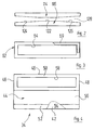
- FIG. 10 denotes a housing as a whole, in which sheet metal pieces 12 from above and below with a Lubricant mist cone 14 or 14 'brought into contact become.
- the housing has a top wall 16, an inlet side Transverse wall 18, an outlet-side transverse wall 20, parallel to the direction of conveyance of the sheets (indicated by arrow 22) extending side walls 24 and a bottom wall 26, which at the same time as a collecting tub for not from the sheet metal pieces 12 entrained litter oil is used.
- Transport rollers are located in the side walls 24 of the housing 10 28 stored, which is a horizontal funding level for specify the sheet metal pieces 12.
- the transport rollers 28 are driven by a common toothed belt 30 which the output gear 32 of a not shown Drive motor works.
- the entry-side transverse wall 18 consists of two pivotable Doors 34, 36, which are mirror images of through the transport rollers 28 arranged conveyor plane are.
- the exit-side transverse wall 20 is a mirror image of the Cross wall 18 constructed from two doors 38, 40.
- the door 34 (see FIG. 4) has an outer wall 42 and one inner wall 44 spaced therefrom from the interior of the housing upper ends of outer wall 42 and inner wall 44 are connected by an edge wall 46.
- edge wall 46 To the front or ends of the door 38 to be thought behind the plane of the drawing, 40 is that through outer wall 42, inner wall 44 and edge wall 46 channel formed by end walls 48 in the longitudinal direction of the channel locked.
- the inner wall 44 an upper wall portion spaced more from the outer wall 50 and just a little bit from the outer wall 42 spaced lower wall section 52.
- the lower ends of outer wall 42 and wall section 52 define one Suction slot 54.
- the wall sections 50 and 52 are through an oblique central wall section 56 connected, such that the transverse cross section of the door 34 one Rectangle with a right-angled triangle and corresponds to the beak carried by the latter.
- connection opening 58 In the wall section 50 there is a close to its edges extending connection opening 58 is provided.
- the door 34 is over at its upper outer end a hinge 60 is pivotally attached to the housing 10.
- the closed position of the doors is shown in FIG.
- Each of the doors can hinge around the associated one be pivoted away from the housing to access the Preserve the interior of the housing.
- Suction shafts are provided, and the suction shafts are over Lines 70, 72 with the input of an electrostatic filter 74 connected. Its output is one with the input Suction blower 76 connected.
- a hollow profile 78 is provided inside the housing 10 , which limited a compressed air channel 80.
- the hollow profile 78 carries via solenoid valves 82 spray heads 84, which under regular Distance along the hollow profile 78 are distributed.
- a second hollow profile 86 is thermally conductive with its underside placed on the top of the hollow profile 78. It delimits a lubricant channel 88.
- the latter is connected by hoses 90 to injectors 72 which correspond to injection nozzles used in diesel engines and serve the that supplied via the lubricant channel 88 Atomize lubricant finely.
- the one from the compressed air duct 80 via the solenoid valves 82 to the spray heads Air supplied serves to support the nebulization and the mist cone generated by the injectors 92 14 to shape, in particular to flatten.
- the injection nozzles 92 extend with their end section through matching openings in a section 96 an angled shield 98.
- the section 96 of the shield plate 98 is inclined so much that larger drops of lubricant that grow together of fog droplets on the shielding plate, below Drain gravity down along the sheet.
- An inclination ensuring such a flow a sheet is used in the present description and referred to in the claims as the run-off angle. At the The exemplary embodiment considered here is the run-off angle about 20 °.
- the section 96 of the shield plate 98 extends until against the wall section 56 and settles in one bevelled end section 100, which is parallel to the wall section 56 of the door 38 runs.
- the shield plate has immediately upstream of section 96 98 a further under opposite discharge angle arranged section 102, which extends up to the wall section 56 extends the door 34 and there again has small end portion 104, the positive abuts the wall section 56.
- the geometry shown in the drawing shows the axis of the spray heads 84 perpendicular to the section 96 of the shield plate 98 and thus closes with the conveyor level the sheets 12 form an angle of approximately 70 °, so that the fog cone 14 with one of the conveying direction 22 opposite speed component on a underlying sheet metal 12 strikes.
- a floor pan 130 is provided in the electrostatic filter 74, which collects the lubricant deposited there.
- the lowest point of the bottom wall 130 is via a drain line 132 with the through the bottom wall 26 of the housing 10 lubricant sump formed. The Do not dispose of lubricant that has been taken from the metal sheets can be done at a central point namely when the bottom wall 26 runs out.
- a piece of sheet metal to be sprayed reaches one by one predetermined distance arranged in front of the fog cones 14
- Position transmitter 134 the spray heads 84 are activated and create the fog cones 14. Moving forward of the sheet metal piece 12 on the transport rollers 28 then both sides of the sheet metal piece 12 with lubricant mist busy. Reaches the rear end of the piece of sheet metal 12 one behind the by a predetermined distance Fog cone 14 arranged position transmitter 136, the Mist generation by the spray heads 84 ended.
- the suction power of the suction fan is preferably 76 approximately ten times the volume of the spray heads 84 fed Air volume. This ensures that no air containing lubricant mist from the Housing 10 emerges.
- a lower limit for suction power of the suction fan 76 is at five times the Seen the volume of air supplied, an increase in Suction power of the suction fan 76 over twenty times of the volume of compressed air supplied would be unnecessary air suck from the area around the housing.
- the doors 34 to 40 can be moved around their Hinges 60 to be given away.
- the upper doors 38 and 40 can and in the open position by lever 138 can be locked, which is pivoted through these doors and with housing-fixed mounting bolts (not shown) work together.
- the bottom wall 26 also collects oil to be sprayed Pieces of sheet metal 12 with different edge contours by gaps between such sheet metal pieces 12 flows through.
- connection openings 64 and 58 do not cover the whole Cross section of the suction shaft 62 or the one facing it Wall section 50 of the inner wall 44 of the hollow-walled door 34. Facing each other with the door 34 closed frontal connecting walls that the wall section 50 and the suction shaft 62 in this embodiment complete, there is a round connection opening executed near one of the end walls 48.
- the Diameter of these two aligned connection openings is about the size of the narrow side of the rectangular connection opening 64 of the related with Figures 3 and 4 embodiment described.
Abstract
Description
Die Erfindung betrifft eine Vorrichtung zum Besprühen von flachen Werkstücken, insbesondere Blechen, mit einer Flüssigkeit, z.B. einem Schmiermittel gemäß dem Oberbegriff des Anspruches 1.The invention relates to a device for spraying of flat workpieces, especially sheet metal, with a Liquid, e.g. a lubricant according to the preamble of claim 1.
Derartige Vorrichtungen werden insbesondere in Verbindung mit Pressenstraßen verwendet, um die zu pressenden oder tiefzuziehenden Bleche mit einem Schmiermittel zu besprühen. Hierdurch werden Riß- und Ziehspurbildung im Werkstück vemieden und wird eine Verringerung der zur Verformung notwendigen Kraft und eine Schonung der Preßwerkzeuge erreicht.Such devices are particularly in connection with press lines used to press or to spray deep-drawn sheets with a lubricant. This will cause cracking and drawing marks in the workpiece avoided and will reduce the deformation necessary force and protection of the pressing tools reached.
Eine derartige Vorrichtung ist aus der EP 0 060 375 A2 bekannt. Dort wird die Saugeinrichtung mit relativ geringer Saugleistung betrieben, damit Sprühfächer, die aus den Sprühköpfen austreten, durch Luftbewegungen nicht gestört werden. Dies reduziert die Wirksamkeit der Saugeinrichtung bei der Einstellung definierter Strömungsverhältnisse innerhalb des Gehäuses der Sprühvorrichtung.Such a device is known from EP 0 060 375 A2 known. There the suction device becomes relatively smaller Suction power operated, so that spray fans emerge from the spray heads due to air movements not be disturbed. This reduces the effectiveness the suction device when setting Flow conditions within the housing of the spray device.
Bei derartigen bekannten Vorrichtungen wird zwar durch ein die Sprühkopfanordnung umgebendes Gehäuse verhindert, daß große Nebelmengen in die Umgebung austreten. Durch die Durchtrittsfenster für die Werkstücke tritt aber Flüssigkeitsnebel aus, der sich auf benachbarten Maschinen und auf der Aufstellfläche als zunehmend dickerer Film niederschlägt, was im Hinblick auf die Reinhaltung der Atemluft und auf die Sauberhaltung der Aufstellfläche und potentielle Unfallgefahr nachteilig ist.In such known devices, although prevents a housing surrounding the spray head arrangement, that large amounts of fog escape into the environment. By however, the passage window for the workpieces enters liquid mist from that on neighboring machines and on the footprint as an increasingly thicker film precipitates what in terms of keeping the Breathing air and keeping the installation area clean potential risk of accident is disadvantageous.
Der Einsatz einer Saugeinrichtung innerhab einer derartigen Vorrichtung ist aus der EP 0 060 375 A2 bekannt. Dort wird die Saugeinrichtung mit relativ geringer Saugleistung betrieben, damit Sprühfächer, die aus den Sprühköpfen austreten, durch Luftbewegungen nicht gestört werden. Dies reduziert die Wirksamkeit der Saugeinrichtung bei der Einstellung definierter Strömungsverhältnisse innerhalb des Gehäuses der Sprühvorrichtung und damit ihre Effizienz bei der Absaugung von Nebel.The use of a suction device within such The device is known from EP 0 060 375 A2. There the suction device with relatively low suction power operated to allow spray fans out of the spray heads emerge, are not disturbed by air movements. This reduces the effectiveness of the suction device the setting of defined flow conditions within the housing of the spray device and thus its efficiency when extracting fog.
Durch die vorliegende Erfindung soll daher eine Einrichtung zum Besprühen von flachen Werkstücken so weitergebildet werden, daß an den Durchtrittsfenstern des Gehäuses sicher kein Flüssigkeitsnebel austritt.The present invention is therefore intended to provide a device further developed for spraying flat workpieces be that on the passage windows of the housing certainly no liquid mist escapes.
Diese Aufgabe ist erfindungsgemäß gelöst durch eine Einrichtung mit dem im Anspruch 1 angegebenen Merkmalen.According to the invention, this object is achieved by a device with the features specified in claim 1.
Bei der erfindungsgemäßen Vorrichtung wird durch die den Durchtrittsöffnungen benachbarten Hohlwandabschnitte hindurch etwa zu den Durchtrittsöffnungen gelangender Flüssigkeitsnebel mit definierter Saugleistung abgesaugt. Damit wird die Umgebung sauber gehalten.In the device according to the invention by the Through openings adjacent cavity wall sections liquid mist reaching the passage openings suctioned with a defined suction power. This keeps the environment clean.
Vorteilhafte Weiterbildungen der Erfindung sind in Unteransprüchen angegeben.Advantageous developments of the invention are in the subclaims specified.
Eine Vorrichtung, wie sie im Anspruch 2 wiedergegeben ist, saugt sowohl oberhalb der Förderebene der Werkstücke austretenden Flüssigkeitsnebel als auch unterhalb der Werkstück-Förderebene austretende Fördernebel im Bereich der Durchtrittsöffnungen des Gehäuses ab. Dies ist insbesondere dann von Vorteil, wenn das Werkstück von beiden Seiten her besprüht wird.A device as reproduced in claim 2 sucks both above the conveying level of the workpieces escaping liquid mist as well as below the Conveying mist emerging from the workpiece conveyor level in the area the passage openings of the housing. This is particularly so then an advantage if the workpiece is both Sides is sprayed here.
Die Weiterbildung der Erfindung gemäß Anspruch 3 gestattet es, die Größe der Saugwirkungen bei den Durchtrittsöffnungen nach Bedarf einzustellen, indem man bei jedem Absaugschlitz zumindest einen Blendenkörper verstellt.The development of the invention according to claim 3 allows it, the size of the suction effects at the passage openings adjust as needed by using each suction slot adjusted at least one aperture body.
Die Weiterbildung der Erfindung gemäß Anspruch 4 gestattet es, die Breite des Saugschlitzes in Schlitzlängsrichtung zu variieren, um so an verschiedenen Stellen des Saugschlitzes entweder trotz ungleicher Geometrie der Unterdruckbeaufschlagungswege trotzdem eine gleichbleibende Saugleistung zu gewährleisten, oder die Saugleistung in Längsrichtung des Saugschlitzes zu variieren, z.B. in Randbereichen verstärkt zu saugen oder die Saugleistung in solchen Schlitzbereichen herabzusetzen, die durch interne Einbauten des Gehäuses schon besser gegen Flüssigkeitsnebel abgeschattet sind.The development of the invention according to claim 4 allows it, the width of the suction slot in the longitudinal direction of the slot to vary so in different places of the suction slit either despite the unequal geometry of the vacuum pathways still a constant To ensure suction power, or suction power in To vary the longitudinal direction of the suction slot, e.g. in Edge areas to suck or increased suction power in such slot areas, which are reduced by internal Installation of the housing better against liquid mist are shadowed.
Die Weiterbildung der Erfindung gemäß Anspruch 5 gestattet es, die Blendenkörper zugleich als Anlauffläche oder Zentrierhilfen für die Werkstückenden zu verwenden.The development of the invention according to claim 5 allows it, the panel body at the same time as a contact surface or centering aid to be used for the workpiece ends.
Bei einer Vorrichtung gemäß Anspruch 6 hat man für Wartungszwecke einen guten Zugang zum Inneren des Gehäuses.In a device according to claim 6 one has for maintenance purposes good access to the inside of the case.
Dabei ist dann gemäß Anspruch 7 gewährleistet, daß eine große Abmessung aufweisende Verbindungsöffnung zu einem gehäusefesten zugeordneten Saugschacht besteht, wobei man bei geschlossenem Hohlwandabschnitt automatisch eine Abdichtung an der Stoßstelle zwischen Hohlwandabschnitt und Saugschacht erhält.It is then ensured according to claim 7 that a Large dimension connection opening to one Assigned suction shaft fixed to the housing, wherein one automatically with a closed cavity wall section Sealing at the joint between the cavity wall section and receives a suction shaft.
Bei einer Vorrichtung gemäß Anspruch 8 werden von den abgesaugten Flüssigkeitsnebeln noch mitgeschleppte Flüssigkeitsanteile abgeschieden, bevor die abgesaugte Luft in das Gebläse der Saugeinrichtung gelangt.In a device according to claim 8 aspirated liquid mist still entrained liquid parts deposited before the extracted air gets into the blower of the suction device.
Ein Flüssigkeitsabscheider, wie er im Anspruch 9 angegeben ist, eignet sich besonders gut zur wirkungsvollen Abscheidung von Öltröpfchen.A liquid separator as specified in claim 9 is particularly well suited for effective separation of oil droplets.
Mit der Weiterbildung der Erfindung gemäß Anspruch 10
ist gewährleistet, daß die im Flüssigkeitsabscheider anfallende
Flüssigkeit zusammen mit Restflüssigkeit, die
im Inneren des Gehäuses erhalten wird, entsorgt wird.With the development of the invention according to
Die Weiterbildung der Erfindung gemäß Anspruch 11 ist im Hinblick auf verlustfreie Unterdruckbeaufschlagung der durch die Hohlwandabschnitte gebildeten Saugschlitze von Vorteil.The development of the invention is according to claim 11 with regard to lossless negative pressure of the suction slits formed by the cavity wall sections advantageous.
Dabei ist bei der in Anspruch 12 angegebenen Geometrie
vorteilhaft, daß sie sich leicht durch Biegen von Blechen
herstellen läßt und daß man automatisch eine plane Verbindungsfläche
zu einem rahmenfesten Saugschacht hin erhält,
die zusammen mit einer benachbarten planen Seitenfläche
des Saugschachtes eine lösbare Dichtstelle bildet,
ohne daß hier ein nennenswerter Aufwand getrieben werden
müßte.It is in the geometry specified in
Die Weiterbildung der Erfindung gemäß Anspruch 13 erlaubt eine Justierung der gehäusefesten Saugschächte in zur Werkstück-Förderrichtung paralleler Richtung.The development of the invention according to claim 13 allows an adjustment of the suction shafts fixed to the housing Workpiece conveying direction in parallel direction.
Mit der Weiterbildung der Erfindung gemäß Anspruch 14
wird eine Abschattung der von den Sprühköpfen erzeugten
Nebelkegel gegen den Innenraum des Gehäuses erzielt, ohne
daß die Gefahr besteht, daß sich auf den Abschirmblechen
größere Tropfen bilden, die dann auf ein Werkstück herabfallen
könnten und dort die Gleichmäßigkeit des Flüssigkeitsauftrages
beeinträchtigen.With the development of the invention according to
Dabei wird gemäß Anspruch 15 erreicht, daß die sich auf dem Abschirmblech bildenden Tropfen nach beiden Seiten aus dem in Förderrichtung mittleren Bereich des Gehäuses herausgetragen werden.It is achieved according to claim 15 that on the shield forming drops on both sides from the middle of the housing in the conveying direction be carried out.
Gemäß Anspruch 16 erhält man eine Abdichtung des Gehäuseinneren
gegen direkte Beaufschlagung mit Flüssigkeitsnebel
vom eintrittsseitigen Durchtrittsfenster des Gehäuses
bis hin zum austrittsseitigen Durchtrittsfenster.According to
Dabei ist die Weiterbildung gemäß Anspruch 17 im Hinblick auf eine gute Randabdichtung zwischen Abschirmblech und Gehäuse von Vorteil.The training according to claim 17 is in view a good edge seal between the shielding plate and Housing is an advantage.
Nachstehend wird die Erfindung anhand eines Ausführungsbeispieles unter Bezugnahme auf die beiliegende Zeichnung näher erläutert. In dieser zeigen:
- Figur 1:
- einen longitudinalen vertikalen Mittelschnitt durch eine Station zum Besprühen von Blechen mit Schmiermittel;
- Figur 2:
- eine Aufsicht auf zwei Blendenkörper, die zum Einstellen der Breite eines konturierten Absaugschlitzes der in Figur 1 gezeigten Station dienen;
- Figur 3:
- eine Aufsicht auf die außenliegende Wand eines Saugschachtes der Station nach Figur 1; und
- Figur 4:
- eine Aufsicht auf die innenliegende Wand einer hohlwandigen Tür der Station nach Figur 1.
- Figure 1:
- a longitudinal vertical central section through a station for spraying metal sheets with lubricant;
- Figure 2:
- a plan view of two diaphragm body, which are used to adjust the width of a contoured suction slot of the station shown in Figure 1;
- Figure 3:
- a view of the outer wall of a suction shaft of the station of Figure 1; and
- Figure 4:
- a top view of the inner wall of a hollow-walled door of the station of Figure 1.
In Figur 1 ist mit 10 insgesamt ein Gehäuse bezeichnet,
in welchem Blechstücke 12 von oben und unten mit einem
Schmiermittelnebelkegel 14 bzw. 14' in Kontakt gebracht
werden.In Figure 1, 10 denotes a housing as a whole,
in which
Das Gehäuse hat eine Deckenwand 16, eine einlaßseitige
Querwand 18, eine auslaßseitige Querwand 20, parallel
zur Förderrichtung der Bleche (angedeutet durch Pfeil
22) verlaufende Seitenwände 24 und eine Bodenwand 26,
die zugleich als Sammelwanne für nicht von den Blechstücken
12 mitgenommenes Streuöl dient.The housing has a
In den Seitenwänden 24 des Gehäuses 10 sind Transportrollen
28 gelagert, die eine horizontale Förderebene für
die Blechstücke 12 vorgeben. Die Transportrollen 28 sind
durch einen gemeinsamen Zahnriemen 30 angetrieben, auf
welchen das Abtriebsritzel 32 eines nicht näher dargestellten
Antriebsmotors arbeitet.Transport rollers are located in the
Die eintrittsseitige Querwand 18 besteht aus zwei verschwenkbaren
Türen 34, 36, die spiegelbildlich zur durch
die Transportrollen 28 vorgebenen Förderebene angeordnet
sind.The entry-side
Die austrittsseitige Querwand 20 ist spiegelbildlich zur
Querwand 18 aus zwei Türen 38, 40 aufgebaut.The exit-side
Da der Aufbau der Türen symmetrisch ist, reicht es, den
Aufbau einer einzigen Tür, nämlich der Tür 34 genauer
zu beschreiben.Since the structure of the doors is symmetrical, it is enough to
Construction of a single door, namely
Die Tür 34 hat (vgl. Figur 4) eine Außenwand 42 und eine
hiervon zum Gehäuseinneren beabstandete Innenwand 44. Die
oben liegenden Enden von Außenwand 42 und Innenwand 44
sind durch eine Randwand 46 verbunden. An den vor bzw.
hinter der Zeichenebene zu denkenden Enden der Türe 38,
40 ist die durch Außenwand 42, Innenwand 44 und Randwand
46 gebildete Rinne durch Stirnwände 48 in Rinnenlängsrichtung
verschlossen.The door 34 (see FIG. 4) has an
Wie aus der Zeichnung ersichtlich, hat die Innenwand 44
einen stärker von der Außenwand beabstandeten oberen Wandabschnitt
50 und einen nur wenig von der Außenwand 42
beabstandeten unteren Wandabschnitt 52. Die unteren Enden
von Außenwand 42 und Wandabschnitt 52 begrenzen einen
Absaugschlitz 54. Die Wandabschnitte 50 und 52 sind durch
einen schrägen mittleren Wandabschnitt 56 verbunden, derart,
daß der transversale Querschnitt der Türe 34 einem
Rechteck mit unten angesetztem rechtwinkligem Dreieck
und von letzterem getragenem Schnabel entspricht.As can be seen from the drawing, the
In dem Wandabschnitt 50 ist ein sich bis in die Nähe von
dessen Rändern erstreckende Verbindungsöffnung 58 vorgesehen.In the
Die Tür 34 ist bei ihrem oberen außen liegenden Ende über
ein Scharnier 60 verschwenkbar am Gehäuse 10 angebracht.
In der Figur 1 ist die Schließstellung der Türen wiedergegeben.
Jede der Türen kann um das zugeordnete Scharnier
vom Gehäuse weggeschwenkt werden, um einen Zugang zum
Gehäuseinneren zu erhalten.The
Bei geschlossener Tür 34 liegt an der Außenfläche des
Wandabschnittes 50 die Seitenfläche eines Saugschachtes
62 an, in welcher eine der Verbindungsöffnung 58 entsprechende
Verbindungsöffnung 64 vorgesehen ist. Die Enden
der Saugschachtes 62 sind über Tragplatten 66 und zugeordnete
Stift/Langlochführungen 68 vom Gehäuse 10 getragen.
Auf diese Weise kann man den Saugschacht 62 so
in Förderrichtung der Bleche 12 verstellen, daß bei geschlossener
Tür 34 eine Spaltdichtung zwischen dem Wandabschnitt
50 und dem Saugschacht 62 erhalten wird. Ggf.
kann auf die stehengebliebenen Ränder des Saugschachtes
62 bzw. des Wandabschnittes 50 ein elastomerer Dichtrahmen
69 (Figur 3) aufgesetzt werden.When the
Durch diese Verbindung zwischen dem Inneren der Tür 34
und dem Saugschacht 62 ist einerseits die Verschwenkbarkeit
der Tür 34 gewährleistet, andererseits bei geschlossener
Tür eine strömungsdichte Verbindung vom Saugschacht
62 zum Inneren der Tür 34 gewährleistet.Through this connection between the inside of the
Für die anderen Türen 36 bis 40 sind analog zugeordnete
Saugschächte vorgesehen, und die Saugschächte sind über
Leitungen 70, 72 mit dem Eingang eines Elektrofilters
74 verbunden. Dessen Ausgang ist mit dem Eingang eines
Sauggebläses 76 verbunden.For the
Im Inneren des Gehäuses 10 ist zwischen dessen Seitenwänden
24 verlaufend ein Hohlprofil 78 vorgesehen, welches
einen Druckluftkanal 80 begrenzt. Das Hohlprofil 78 trägt
über Magnetventile 82 Sprühköpfe 84, die unter regelmäßigem
Abstand längs des Hohlprofiles 78 verteilt sind.Inside the
Ein zweites Hohlprofil 86 ist mit seiner Unterseite wärmeleitend
auf die Oberseite des Hohlprofiles 78 aufgesetzt.
Es begrenzt einen Schmiermittelkanal 88. Letzterer ist
über Schläuche 90 mit Einspritzdüsen 72 verbunden, die
in Dieselmotoren verwendeten Einspritzdüsen entsprechen
und dazu dienen, das über den Schmiermittelkanal 88 zugeführte
Schmiermittel fein zu zerstäuben. Die vom Druckluftkanal
80 über die Magnetventile 82 den Sprühköpfen
zugeführte Luft dient dazu, die Vernebelung zu unterstützen
und den von den Einspritzdüsen 92 erzeugten Nebelkegel
14 zu formen, insbesondere plattzudrücken.A second
Die Einspritzdüsen 92 erstrecken sich mit ihrem Endabschnitt
durch passende Öffnungen in einem Abschnitt 96
eines abgewinkelten Abschirmbleches 98. Der Abschnitt
96 des Abschirmbleches 98 ist so stark geneigt, daß sich
größere Schmiermitteltropfen, die durch Zusammenwachsen
von Nebeltröpfchen auf dem Abschirmblech entstehen, unter
Schwerkrafteinwirkung längs des Bleches nach unten abfließen.
Eine ein solches Abfließen gewährleistende Neigung
eines Bleches wird in der vorliegenden Beschreibung
und in den Ansprüchen als Ablaufwinkel bezeichnet. Beim
hier betrachteten Ausführungsbeispiel beträgt der Ablaufwinkel
etwa 20°.The injection nozzles 92 extend with their end section
through matching openings in a
Der Abschnitt 96 des Abschirmbleches 98 erstreckt sich
bis gegen den Wandabschnitt 56 und setzt sich in einem
abgekanteten Endabschnitt 100 fort, der parallel zum Wandabschnitt
56 der Türe 38 verläuft.The
Unmittelbar stromauf des Abschnittes 96 hat das Abschirmblech
98 einen weiter unter entgegengesetztem Ablaufwinkel
angeordneten Abschnitt 102, der sich bis zum Wandabschnitt
56 der Tür 34 erstreckt und dort wieder einen
kleinen Endabschnitt 104 aufweist, der formschlüsssig
an dem Wandabschnitt 56 anliegt.The shield plate has immediately upstream of
Bei der in der Zeichnung wiedergegebenen Geometrie steht
die Achse der Sprühköpfe 84 senkrecht auf dem Abschnitt
96 des Abschirmbleches 98 und schließt somit mit der Förderebene
der Bleche 12 einen Winkel von etwa 70° ein,
so daß der Nebelkegel 14 mit einer der Förderrichtung
22 entgegengesetzten Geschwindigkeitskomponente auf ein
darunter liegendes Blech 12 auftrifft. The geometry shown in the drawing shows
the axis of the spray heads 84 perpendicular to the
Die geometrischen Verhältnisse im unteren Abschnitt des
Gehäuses 10 sind spiegelbildlich zu den soeben erläuterten
Verhältnissen im oberen Abschnitt.The geometric relationships in the lower section of the
Um die effektive Saugleistung bei den durch die Türen
34, 36 bzw. 38, 40 begrenzten Durchtrittsfenstern des
Gehäuses 10 einstellen zu können, haben die Außenwand
42 und die Innenwand 44 untere Endabschnitte 110 bzw.
112, die jeweils entgegengesetzt zueinander unter etwa
25° zur Förderebene der Blechstücke 12 angestellt sind.
Auf den Endabschnitten 110, 112 ist jeweils ein Blendenkörper
114 bzw. 116 in Förderrichtung verschiebbar angeordnet
und durch Schrauben 118, 120 in der jeweils eingestellten
Stellung fixierbar. Damit begrenzen die Blendenkörper
114, 116 jeweils den effektiven Absaugschlitz,
der an den der Förderebene benachbarten Enden der Türen
34 bis 40 vorliegt.To ensure effective suction power through the
Wie aus Figur 2 ersichtlich, kann man die freien Randkanten
der Blendenkörper 114, 116 konturieren, z.B. einen
mittleren exakt in Längsrichtung aufweisenden Randkantenabschnitt
122 vorsehen, an den sich zu den Enden der Blendenkörper
hin zunehmend zurückspringende Randabschnitte
124, 126 anschließen. Auf diese Weise begrenzen die Blendenkörper
114, 116 zusammen einen Saugschlitz 128, dessen
Breite zu den seitlichen Rändern des Durchtrittsfensters
hin zunimmt. Auf diese Weise kann man eine etwaige schlechtere
Unterdruckbeaufschlagung bei den seitlichen Enden
des Saugschlitzes 128 kompensieren oder eine verstärkte
Saugwirkung bei den Enden des Saugschlitzes 128 vorgeben.As can be seen from Figure 2, you can see the free edge
contour the
In dem Elektrofilter 74 ist eine Bodenwanne 130 vorgesehen,
welche das dort abgeschiedene Schmiermittel sammelt.
Die tiefste Stelle der Bodenwand 130 ist über eine Ablaufleitung
132 mit der durch die Bodenwand 26 des Gehäuses
10 gebildeten Schmiermittel-Sammelwanne verbunden. Die
Entsorgung nicht von den Blechen mitgenommenen Schmiermittels
kann somit an einer zentralen Stelle erfolgen,
nämlich beim Ablauf der Bodenwand 26.A
Die oben beschriebene Sprühanlage arbeitet folgendermaßen:The spray system described above works as follows:
Erreicht ein zu besprühendes Blechstück einen um eine
vorgegebene Strecke vor den Nebelkegeln 14 angeordneten
Stellungsgeber 134, so werden die Sprühköpfe 84 aktiviert
und erzeugen die Nebelkegel 14. Beim weiteren Vorwärtsbewegen
des Blechstückes 12 auf den Transportrollen 28
werden dann beide Seiten des Blechstückes 12 mit Schmiermittelnebel
belegt. Erreicht das hintere Ende des Blechstückes
12 einen um eine vorgegebene Strecke hinter den
Nebelkegeln 14 angeordneten Stellungsgeber 136, wird die
Nebelerzeugung durch die Sprühköpfe 84 beendet.If a piece of sheet metal to be sprayed reaches one by one
predetermined distance arranged in front of the
Sowohl beim Anschalten als auch beim Abschalten der Sprühköpfe
84 wird Schmiermittelnebel schon erzeugt oder noch
erzeugt, obwohl kein Blechstück in den Nebelkegeln 14
steht. Steht ein Blechstück 12 in den Nebelkegeln 14, wird
ein Teil des auf die Blechoberflächen gerichteten Nebels
von der Blechoberfläche reflektiert. Es bildet sich damit
im gesamten zwischen den beiden Abschirmblechen 98 liegenden
Raum ein Schmiermittelnebel aus. Ein Teil dieses
Schmiermittelnebels sucht durch die Durchtrittsfenster
106 und 108 zur Umgebung hin auszutreten.Both when switching on and when switching off the spray heads
84 lubricant mist is already being generated or still is
generated, although no piece of sheet metal in the
Da aber die Türen 34 bis 40 als Hohlkammerelemente ausgebildet
sind und über die Saugschächte 62 mit dem Elektrofilter
74 und dem Sauggebläuse 76 in Verbindung stehen,
werden die zwischen den Türen 34 und 36 bzw. 38, 40 auszutreten
suchenden Nebelmengen abgesaugt, bevor sie in
die Umgebung entweichen. Im Elektrofilter 74 wird das
im zurückgesaugten Nebel enthaltene Schmiermittel abgeschieden
und von dort der durch die Bodenwand 26 gebildeten
Sammelwanne zugeführt.But since the
Auf diese Weise ist eine Verunreinigung der Umgebung der Station durch austretende Schmiermittelnebel ausgeräumt.In this way, pollution of the environment is Station cleared by escaping lubricant mist.
Vorzugsweise beträgt die Saugleistung des Sauggebläses
76 etwa das zehnfache Volumen des den Sprühköpfen 84 zugeführten
Luftvolumens. Auf diese Weise ist gewährleistet,
daß keine Schmiermittelnebel enthaltende Luft aus dem
Gehäuse 10 austritt. Eine untere Grenze für die Saugleistung
des Sauggebläses 76 wird bei dem fünffachen des
Volumens der zugeführten Luft gesehen, eine Erhöhung der
Saugleistung des Sauggebläses 76 über das zwanzigfache
des Volumens der zugeführten Druckluft würde unnötig Luft
aus der Umgebung des Gehäuses ansaugen.The suction power of the suction fan is preferably
76 approximately ten times the volume of the spray heads 84 fed
Air volume. This ensures
that no air containing lubricant mist from the
Zu Wartungszwecken können die Türen 34 bis 40 um ihre
Scharniere 60 verschenkt werden. Die oberen Türen 38 und
40 können und in der Offenstellung durch Aufstellhebel
138 arretiert werden, die durch diese Türen mit verschwenkt
werden und mit gehäusefesten Aufstellbolzen (nicht gezeigt)
zusammenarbeiten.For maintenance purposes, the
Die Bodenwand 26 fängt auch Öl auf, das an zu besprühenden
Blechstücken 12 mit unterschiedlicher Randkontur vorbei- oder
durch Lücken zwischen derartigen Blechstücken 12
hindurchfließt.The
Bei einer alternativen Ausführungsform erstrecken sich
die Verbindungsöffnungen 64 und 58 nicht über den gesamten
Querschnitt des Saugschachtes 62 bzw. des ihm zugewandten
Wandabschnitts 50 der Innenwand 44 der hohlwandigen Tür
34. In einander bei geschlossener Tür 34 zugewandten
stirnseitigen Verbindungswänden, die den Wandabschnitt
50 und den Saugschacht 62 bei dieser Ausführungsform
abschließen, ist jeweils eine runde Verbindungsöffnung
in der Nähe einer der Stirnwände 48 ausgeführt. Der
Durchmesser dieser beiden fluchtenden Verbindungsöffnungen
ist in etwa so groß ist wie die Schmalseite der
rechteckigen Verbindungsöffnung 64 des in Zusammenhang
mit den Figuren 3 und 4 beschriebenen Ausführungsbeispiels.In an alternative embodiment, extend
the
Claims (18)
Applications Claiming Priority (2)
| Application Number | Priority Date | Filing Date | Title |
|---|---|---|---|
| DE19916762 | 1999-04-14 | ||
| DE19916762A DE19916762A1 (en) | 1999-04-14 | 1999-04-14 | Device for spraying workpieces with a liquid |
Publications (1)
| Publication Number | Publication Date |
|---|---|
| EP1044725A2 true EP1044725A2 (en) | 2000-10-18 |
Family
ID=7904481
Family Applications (1)
| Application Number | Title | Priority Date | Filing Date |
|---|---|---|---|
| EP00106489A Withdrawn EP1044725A2 (en) | 1999-04-14 | 2000-03-25 | Apparatus for spraying a liquid on workpieces |
Country Status (2)
| Country | Link |
|---|---|
| EP (1) | EP1044725A2 (en) |
| DE (1) | DE19916762A1 (en) |
Cited By (2)
| Publication number | Priority date | Publication date | Assignee | Title |
|---|---|---|---|---|
| WO2002055215A2 (en) * | 2001-01-12 | 2002-07-18 | Josef Schiele Ohg | Coating device for a rectangular workpiece |
| EP2006029A3 (en) * | 2007-06-19 | 2012-06-20 | Amtec Kistler GmbH | Device for applying an application to a substrate |
Families Citing this family (4)
| Publication number | Priority date | Publication date | Assignee | Title |
|---|---|---|---|---|
| DE10159443B4 (en) * | 2001-12-04 | 2006-05-04 | Zimmer Ag | Device for changing nozzles |
| DE102005062527A1 (en) * | 2005-12-16 | 2007-06-21 | Gebr. Schmid Gmbh & Co. | Substrate surface treatment device for production of solar cell, has suction unit provided for suction of fluid process medium from environment of conveying unit and arranged under transport plane in vertical direction |
| DE102013006331A1 (en) * | 2013-04-12 | 2014-10-16 | Technotrans Ag | Workpiece lubricator and method for lubricating workpieces |
| DE102014213401A1 (en) | 2014-03-28 | 2015-10-01 | Sms Group Gmbh | Apparatus for applying and extracting operating fluids in the inlet of cold rolling mills |
Citations (1)
| Publication number | Priority date | Publication date | Assignee | Title |
|---|---|---|---|---|
| EP0060375A2 (en) | 1981-03-13 | 1982-09-22 | VOEST-ALPINE Aktiengesellschaft | Apparatus for lubricating strip or web sheet metal |
Family Cites Families (5)
| Publication number | Priority date | Publication date | Assignee | Title |
|---|---|---|---|---|
| US2400315A (en) * | 1944-06-10 | 1946-05-14 | Jens A Paasche | Coating machine |
| DE1796280A1 (en) * | 1967-07-24 | 1972-11-09 | Mcmillan Bloedel Ltd | Method and device for spraying liquids |
| US3475202A (en) * | 1967-10-19 | 1969-10-28 | Hendrik F Bok | Method for controlling a spray-coating environment |
| FR2551365B1 (en) * | 1983-08-01 | 1986-03-28 | Lorraine Laminage | DEVICE FOR OILING SHEETS IN CONTINUOUS TAPE |
| DE4316672C1 (en) * | 1993-05-13 | 1994-07-28 | Mannesmann Ag | Device for the production of metallic bodies by spraying |
-
1999
- 1999-04-14 DE DE19916762A patent/DE19916762A1/en not_active Withdrawn
-
2000
- 2000-03-25 EP EP00106489A patent/EP1044725A2/en not_active Withdrawn
Patent Citations (1)
| Publication number | Priority date | Publication date | Assignee | Title |
|---|---|---|---|---|
| EP0060375A2 (en) | 1981-03-13 | 1982-09-22 | VOEST-ALPINE Aktiengesellschaft | Apparatus for lubricating strip or web sheet metal |
Cited By (3)
| Publication number | Priority date | Publication date | Assignee | Title |
|---|---|---|---|---|
| WO2002055215A2 (en) * | 2001-01-12 | 2002-07-18 | Josef Schiele Ohg | Coating device for a rectangular workpiece |
| WO2002055215A3 (en) * | 2001-01-12 | 2002-09-19 | Josef Schiele Ohg | Coating device for a rectangular workpiece |
| EP2006029A3 (en) * | 2007-06-19 | 2012-06-20 | Amtec Kistler GmbH | Device for applying an application to a substrate |
Also Published As
| Publication number | Publication date |
|---|---|
| DE19916762A1 (en) | 2000-11-02 |
Similar Documents
| Publication | Publication Date | Title |
|---|---|---|
| EP0765696B1 (en) | Device for keeping cold rolled strip dry on the outlet of cold rolling and strip plants | |
| EP1979103B1 (en) | Belt cleaning apparatus | |
| EP3423232A1 (en) | Apparatus with extraction device | |
| EP0780332B1 (en) | Device for acting on sheets in a sheet delivery apparatus | |
| DE19614046A1 (en) | Output conveyor unit for a printing press | |
| DE3640699C2 (en) | ||
| EP0533054A2 (en) | Device for purification of liquid baths | |
| DE19705006C2 (en) | Device for supplying and extracting ink in printing machines | |
| DE2743530C3 (en) | Device for cleaning large surface textures, in particular carpets and carpeting | |
| EP1044725A2 (en) | Apparatus for spraying a liquid on workpieces | |
| DE102010007479B3 (en) | Equipment for coating objects | |
| EP0629425A1 (en) | Bandfilter device for the purification of processing liquids | |
| EP1466670B1 (en) | Device for cleaning a powder coating booth and powder coating booth with a cleaning device | |
| DE3427766A1 (en) | DEVICE FOR GREASING SHEET TAPES | |
| DE2116042A1 (en) | Method and apparatus for removing powder from the atmosphere | |
| AT393237B (en) | NOZZLE FOR DRYING GLASS PANELS | |
| EP0391091B1 (en) | Vacuum belt filtration apparatus | |
| DE19822537A1 (en) | Vehicle body cleaning device | |
| EP2072146A2 (en) | Modular coating enclosure | |
| EP0939592B1 (en) | Paste forming device | |
| DE19521267C2 (en) | Oil mist remover for the oil control system of a press | |
| DE10236264A1 (en) | Powdering unit for printing press has powder curtain movable between two angled guide elements each with one member located parallel or coplanar with each other and one member extending parallel to powder curtain plane | |
| DE629418C (en) | Dusting device | |
| DE3910930C2 (en) | ||
| DE2420824C2 (en) | A device arranged between two treatment zones arranged one behind the other for treating flat, metallic sheets or strips with liquids of different types to prevent the one liquid from overflowing into the adjacent treatment zone |
Legal Events
| Date | Code | Title | Description |
|---|---|---|---|
| PUAI | Public reference made under article 153(3) epc to a published international application that has entered the european phase |
Free format text: ORIGINAL CODE: 0009012 |
|
| AK | Designated contracting states |
Kind code of ref document: A2 Designated state(s): AT BE CH CY DE DK ES FI FR GB GR IE IT LI LU MC NL PT SE |
|
| AX | Request for extension of the european patent |
Free format text: AL;LT;LV;MK;RO;SI |
|
| STAA | Information on the status of an ep patent application or granted ep patent |
Free format text: STATUS: THE APPLICATION IS DEEMED TO BE WITHDRAWN |
|
| 18D | Application deemed to be withdrawn |
Effective date: 20021001 |