EP1044321B1 - Moteurs de turbine a gaz connectes en serie - Google Patents
Moteurs de turbine a gaz connectes en serie Download PDFInfo
- Publication number
- EP1044321B1 EP1044321B1 EP98964976A EP98964976A EP1044321B1 EP 1044321 B1 EP1044321 B1 EP 1044321B1 EP 98964976 A EP98964976 A EP 98964976A EP 98964976 A EP98964976 A EP 98964976A EP 1044321 B1 EP1044321 B1 EP 1044321B1
- Authority
- EP
- European Patent Office
- Prior art keywords
- turbine
- compressor
- gas turbine
- gas
- combustor
- Prior art date
- Legal status (The legal status is an assumption and is not a legal conclusion. Google has not performed a legal analysis and makes no representation as to the accuracy of the status listed.)
- Expired - Lifetime
Links
- 239000000446 fuel Substances 0.000 claims description 19
- 230000008878 coupling Effects 0.000 claims 2
- 238000010168 coupling process Methods 0.000 claims 2
- 238000005859 coupling reaction Methods 0.000 claims 2
- 239000007789 gas Substances 0.000 description 43
- 239000003570 air Substances 0.000 description 8
- 238000000034 method Methods 0.000 description 8
- 238000002485 combustion reaction Methods 0.000 description 4
- VNWKTOKETHGBQD-UHFFFAOYSA-N methane Chemical compound C VNWKTOKETHGBQD-UHFFFAOYSA-N 0.000 description 4
- 239000012080 ambient air Substances 0.000 description 3
- 230000006835 compression Effects 0.000 description 3
- 238000007906 compression Methods 0.000 description 3
- 230000009977 dual effect Effects 0.000 description 3
- 238000010248 power generation Methods 0.000 description 3
- 238000010586 diagram Methods 0.000 description 2
- 239000003345 natural gas Substances 0.000 description 2
- PIWKPBJCKXDKJR-UHFFFAOYSA-N Isoflurane Chemical compound FC(F)OC(Cl)C(F)(F)F PIWKPBJCKXDKJR-UHFFFAOYSA-N 0.000 description 1
- 230000003190 augmentative effect Effects 0.000 description 1
- 238000000576 coating method Methods 0.000 description 1
- 239000002131 composite material Substances 0.000 description 1
- 230000003292 diminished effect Effects 0.000 description 1
- 230000005611 electricity Effects 0.000 description 1
- -1 for example Substances 0.000 description 1
- 239000003779 heat-resistant material Substances 0.000 description 1
- 238000009434 installation Methods 0.000 description 1
- 230000002045 lasting effect Effects 0.000 description 1
- 239000000463 material Substances 0.000 description 1
- 229940038570 terrell Drugs 0.000 description 1
Images

Classifications
-
- F—MECHANICAL ENGINEERING; LIGHTING; HEATING; WEAPONS; BLASTING
- F02—COMBUSTION ENGINES; HOT-GAS OR COMBUSTION-PRODUCT ENGINE PLANTS
- F02C—GAS-TURBINE PLANTS; AIR INTAKES FOR JET-PROPULSION PLANTS; CONTROLLING FUEL SUPPLY IN AIR-BREATHING JET-PROPULSION PLANTS
- F02C6/00—Plural gas-turbine plants; Combinations of gas-turbine plants with other apparatus; Adaptations of gas-turbine plants for special use
- F02C6/02—Plural gas-turbine plants having a common power output
-
- F—MECHANICAL ENGINEERING; LIGHTING; HEATING; WEAPONS; BLASTING
- F02—COMBUSTION ENGINES; HOT-GAS OR COMBUSTION-PRODUCT ENGINE PLANTS
- F02C—GAS-TURBINE PLANTS; AIR INTAKES FOR JET-PROPULSION PLANTS; CONTROLLING FUEL SUPPLY IN AIR-BREATHING JET-PROPULSION PLANTS
- F02C3/00—Gas-turbine plants characterised by the use of combustion products as the working fluid
- F02C3/34—Gas-turbine plants characterised by the use of combustion products as the working fluid with recycling of part of the working fluid, i.e. semi-closed cycles with combustion products in the closed part of the cycle
Definitions
- This invention relates to turbo machinery systems and, more particularly, to gas turbine systems.
- a simple gas turbine cycle comprises a compressor, a combustion chamber located downstream of the compressor, and a turbine located downstream of the combustor.
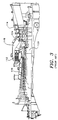
- Figure 3 shows a conventional simple turbine cycle comprising a compressor 116, a turbine section 114, a combustion chamber 118, and a combustor 112. Compressed air from the compressor 116 is directed to the combustion chamber 118 and into the combustor 112 in which fuel, for example, natural gas, is burned in the presence of the compressed air. Hot gases exit the combustor 112 and enter into the turbine 114 where the gas expands to drive a rotor shaft 120. The shaft 120 is also responsible for driving the compressor 116 which consumes a portion of the power output. The remainder of the power output is utilized to drive a generator rotor (not shown in Figure 3), thereby producing electricity.
- U.S. Patent No. 5,465,569 entitled “Method of Establishing Part-Load Operation in a Gas Turbine Group,” to Althaus describes a gas turbine system having a reheat cycle.
- the reheat cycle includes a low pressure combustor and self-igniting low pressure turbine disposed downstream of a simple turbine system like that shown in Figure 3.
- U.S. Patent No. 3,765,170 entitled “Composite Gas Turbine Set" to Nakamura describes a gas turbine system having a regencrative cycle.
- the Nakamura '170 patent includes a standard cycle (including a heat exchanger) ported to a second heat exchanger.
- This system includes a main turbine and auxiliary turbine which accepts bleed air from the main compressor and directs the gas from the auxiliary turbine outlet to the main turbine inlet.
- U.S. Patent No. 2,755,621 entitled “Gas Turbine Installations with Output Turbine By-Pass Matching the Output Turbine Pressure Drop,” to Terrell discloses a gas turbine system having a separate output turbine to accept the main turbine exhaust with by-pass control.
- U.S. Patent No. 5,313,782 "Combined Gas/Steam Power Station Plant,” to Furgingi et al. describes a system having dual compressors with dual, in-line turbines including a reheater and auxiliary intercooler.
- Figure 2 shows an enthalpy versus entropy (h vs. s) diagram of various cycles.
- Curve 1 of Figure 2 represents a simple turbine cycle and Curve 2 of Figure 2 represents a simple turbine cycle augmented by a reheat cycle.
- a compressor compresses the air from p1 to p4.
- the combustion process increases the enthalpy of the gas to h1 by increasing its temperature.
- a turbine expands the gas to a pressure p1 to complete the simple turbine cycle.
- the gas is partially expanded to a pressure P2 through the High Pressure Turbine (HPT) component, which generally consists of one stage.
- HPT High Pressure Turbine
- a second combustor reheats the gas in order to increase the work capacity of the gas.
- the reheat temperature is generally assumed to be equal to the maximum Turbine Inlet Temperature (TIT), i.e., that which corresponds to h1.
- TIT Turbine Inlet Temperature
- h1 the maximum Turbine Inlet Temperature
- Higher TIT's mean more work output and higher cycle efficiency. Since the limiting factor on increasing TIT is the material used to construct the first stage of the turbine, research is underway to produce stronger and more heat-resistant materials and coatings.
- the reheat cycle presents an alternative to producing more power through higher and higher TIT.
- the net power produced by the cycle can simply be measured by subtracting the length of the line of the compression path (4a-4b) from the length of the line of the expansion path (6a-6d).
- Curves 1 and 2 show that the reheat cycle has a longer expansion path line because it has two expansions (i.e., 6a-6b and 8a-8b).
- the efficiency of the cycle is measured by dividing the power output by the energy of the fuel being used.
- a measure of the losses is the entropy generated within the cycle, which is represented by the distance form S1 to S4 for the reheat cycle.
- the reheat process is capable of producing power at the same level as the simple cycle but at lower temperatures, which results in lower costs and longer lasting turbine blades and a more efficient cycle (i.e. that uses less fuel than a simple cycle). Further, the reheat process can produce more power than the conventional simple cycle at comparable efficiency levels using the same maximum TIT.
- the reheat cycle provides some advantages over the simple cycle, the cost of equipment and fuel associated with operating a gas turbine system are high. Therefore, it is an object of the present invention to produce a gas turbine system having high efficiency, high power output for a given size of the components, and minimum overall equipment cost.
- a gas turbine system having a high temperature compression and reheat cycle (HTCR) is provided.
- the first portion of the HTCR system includes a first compressor, a first combustor, and a first turbine.
- the first turbine may be a one or two stage high pressure turbine (HPT) that partially expands the process gas.
- HPT high pressure turbine
- the second part of the HTCR system includes a second compressor, a reheat combustor, and a second turbine.
- the second compressor which may be a single stage or a two stage high temperature compressor, compresses the process gas from the pressure at the first turbine outlet to a higher pressure.
- the reheat combustor heats the process gas to a higher temperature and raises its enthalpy.
- the second gas turbine which may be a three stage or a four stage low pressure turbine (LPT), expands the gas.
- LPT low pressure turbine
- the shaded region of Figure 2 represents the increase in the area under the curve, which represents an increase to the overall efficiency of the HTCR cycle compared with the prior art reheat cycle shown in Curve 2. Furthermore, the inlet temperature to the low pressure turbine, which corresponds to enthalpy h1, of the HTCR cycle is achieved with the addition of much less second combustor fuel input compared with the reheat cycle represented by Curve 2 of Figure 2.
- the HTCR cycle according to the present invention has several advantages over both the simple and the reheat cycles.
- the HTCR cycle is capable of producing considerably more power output than the simple cycle utilizing much less fuel than the reheat cycle.
- the HTCR cycle is more efficient than the reheat cycle due to the decrease in entropy generation.
- the LPT component of the HTCR cycle is capable of increase power generation because it receives inlet gas having a much higher pressure than that received by its counterpart in the prior art reheat cycle. Because the HTCR cycle presents a more efficient cycle that is capable of generating more power than either the simple cycle or the reheat cycle, enhanced efficiency and diminished equipment and fuel operating costs are achieved.
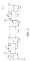
- FIG 1 is a schematic view of the high temperature compression and reheat gas turbine system (HTCR) 10 according to the present invention.
- the HTCR system includes a first compressor 12, a first combustor 14, a first turbine 16, a second compressor 20, a second combustor 24, and a second turbine 26.
- a single shaft machine is preferred.
- a multi-shaft or dual shaft machine may be employed.
- the first compressor 12 and first turbine 16 may have a common shaft 18.
- the second compressor 20 and the second turbine 26 may have a common shaft 28.
- first turbine 16 may have a common shaft 30 with second compressor 20.
- Shafts 18, 28, and 30 are shown in relief in Figure 1 to illustrate that such interconnection may vary according to the design requirements of a particular system, as will be understood by persons familiar with such systems.
- First compressor 12 is preferably a conventional compressor of the type employed in the simple cycle engine.
- first compressor 12 may be a model ATS or 501G compressor having 16 or 20 stages as supplied by Westinghouse Electric Corporation, Pittsburgh, Pennsylvania.
- First turbine 16 is preferably a two stage, high pressure turbine.
- Second compressor 20 is preferably either a single stage or a two stage, high temperature compressor, although a single stage compressor is preferred because of its lower equipment cost.
- Second turbine 26 is preferably a three stage or a four stage low pressure turbine, and may also be a five stage low pressure turbine.
- an air stream 4a enters low temperature compressor 12. Air stream 4a is compressed within low temperature compressor 12 to form compressed air stream 4b at pressure p4, as shown in Figure 2.
- Air stream 4a is compressed within low temperature compressor 12 to form compressed air stream 4b at pressure p4, as shown in Figure 2.
- some reference numerals that refer to a gas stream in Figure 1 also illustrate, in Figure 2, the particular properties of that gas stream at the point shown.
- a fuel stream 5a and compressed air stream 4b are combusted within first combustor 14 to produce a first combustor exit gas stream 6a having an enthalpy h1.
- Fuel stream 5a may comprise any suitable fuel (for example, natural gas) as will be understood by persons familiar with such combustors and fuels. However, fuel stream 5a is not limited to a specific fuel nor even to a fuel in a gaseous state. Further, the term "gas turbine” as used in the specification and appended claims does not refer to a state of the fuel, but rather broadly refers to the type of turbine that may be suitably employed with the HTCR cycle, as will be understood by persons familiar with turbine cycles and equipment.
- First combustor exit gas stream 6a is partially expanded through high pressure turbine 16 to produce a high pressure turbine exit gas stream 6b at pressure p2.
- High pressure compressor 20 compresses gas stream 6b to form a high pressure compressor exit stream 6c at pressure p3.
- a fuel stream 5b is combusted and combined with gas stream 6c in reheat combustor 24 to form reheat combustor exit gas stream 7a at enthalpy h1.
- Gas stream 7a may have an enthalpy h1 that is approximately equal to the enthalpy of gas stream 6a, as illustrated in Figure 2. However, the present invention is not limited to such a relationship of enthalpies.
- Gas stream 7a is expanded through low temperature turbine 26 to produce a low temperature turbine exit gas 7b stream at pressure p1.
- the present invention may be embodied in other specific forms without departing from the spirit or essential attributes thereof. Specifically, the present invention is not limited to certain size or type of components, but rather, the HTCR cycle according to the present invention may be employed with any size or type of engine. Further, the present invention is not limited to a certain interconnection arrangement. For example, the HTCR cycle according to the present invention is equally applicable to circumstances in which all components reside on the same shaft (as typical to power generation engines), concentric shafts (as typical to aero engines), and on separate shafts (e.g., free shafts). Therefore, reference should be made to the appended claims, rather than to the foregoing specification, as indicating the scope of the invention.
Landscapes
- Engineering & Computer Science (AREA)
- Chemical & Material Sciences (AREA)
- Combustion & Propulsion (AREA)
- Mechanical Engineering (AREA)
- General Engineering & Computer Science (AREA)
- Life Sciences & Earth Sciences (AREA)
- Sustainable Development (AREA)
- Engine Equipment That Uses Special Cycles (AREA)
- Structures Of Non-Positive Displacement Pumps (AREA)
- Control Of Turbines (AREA)
Claims (7)
- Système de turbine (10) à gaz comportant :un premier compresseur (12) pour produire un courant (4b) d'air comprimé ;un premier dispositif (14) de combustion, en communication de fluide avec le premier compresseur (12), pour mettre en combustion un courant (5a) de combustible pour produire un premier courant (6a) de gaz de sortie de dispositif de combustion ;une première turbine (16) à gaz, en communication de fluide avec le premier dispositif (14) de combustion, pour dilater partiellement le premier courant (6a) de gaz de sortie du dispositif de combustion pour former un premier courant (6b) de gaz de sortie de turbine ; et caractérisé par le fait de comporter en outre :un deuxième compresseur (20), en communication de fluide avec la première turbine (16) à gaz, pour recevoir et comprimer le premier courant (6b) de gaz de sortie de turbine à gaz pour produire un deuxième courant (6c) de gaz de sortie de compresseur ;un deuxième dispositif (24) de combustion, en communication de fluide avec le deuxième compresseur (20) pour mettre en combustion du combustible (5b) en la présence du deuxième courant (6c) de gaz de sortie de compresseur pour produire un deuxième courant (7a) de gaz de sortie de dispositif de combustion ; etune deuxième turbine (26) à gaz, en communication de fluide avec le deuxième dispositif (24) de combustion, pour dilater le deuxième courant (7a) de gaz de sortie de dispositif de combustion pour former un deuxième courant (7b) de gaz de sortie de turbine à gaz.
- Système (10) de turbine à gaz suivant la revendication 1, dans lequel le deuxième compresseur est un compresseur (20) à haute température comportant l'un parmi un compresseur à un étage et un compresseur à deux étages.
- Système (10) de turbine à gaz suivant la revendication 1, dans lequel la deuxième turbine (26) à gaz comporte une turbine (26) à basse pression ayant trois étages de turbine.
- Système (10) de turbine à gaz suivant la revendication 1, dans lequel la deuxième turbine (26) à gaz comporte une turbine (26) à basse pression ayant quatre étages de turbine.
- Système (10) de turbine à gaz suivant la revendication 1, dans lequel la deuxième turbine (26) à gaz comporte une turbine (26) à base pression ayant au moins cinq étages de turbine.
- Système (10) de turbine à gaz suivant la revendication 1, comportant en outre un premier arbre (18) et un deuxième arbre (28), le premier arbre (18) couplant en rotation le premier compresseur (12) et la première turbine (16) à gaz, le deuxième arbre (28) couplant en rotation le deuxième compresseur (20) et la deuxième turbine (26) à gaz et dans lequel le premier arbre (18) et le deuxième arbre (28) sont couplés en rotation ensemble.
- Système de turbine à gaz à basse pression pour recevoir du gaz (6b) de sortie partiellement dilaté d'un système de turbine à gaz à haute pression, le système de turbine à gaz à basse pression étant caractérisé par le fait de comporter :un compresseur (20) à haute température ayant au moins un étage de compression, pour produire un courant (6c) gazeux de sortie de compresseur à haute température ;un dispositif (24) de combustion de réchauffage, en communication de fluide avec le compresseur (20) à haute température, pour brûler le combustible (5b) en la présence du courant (6c) gazeux de sortie de compresseur à haute température pour produire un courant (7a) gazeux de sortie de dispositif de combustion de réchauffage ; etune turbine (26) basse pression en communication de fluide avec le dispositif (24) de combustion de réchauffage pour dilater le courant (7a) gazeux de sortie de dispositif de combustion de réchauffage.
Applications Claiming Priority (3)
| Application Number | Priority Date | Filing Date | Title |
|---|---|---|---|
| US09/002,544 US6079197A (en) | 1998-01-02 | 1998-01-02 | High temperature compression and reheat gas turbine cycle and related method |
| US2544 | 1998-01-02 | ||
| PCT/US1998/027714 WO1999035383A1 (fr) | 1998-01-02 | 1998-12-30 | Moteurs de turbine a gaz connectes en serie |
Publications (2)
| Publication Number | Publication Date |
|---|---|
| EP1044321A1 EP1044321A1 (fr) | 2000-10-18 |
| EP1044321B1 true EP1044321B1 (fr) | 2002-07-10 |
Family
ID=21701277
Family Applications (1)
| Application Number | Title | Priority Date | Filing Date |
|---|---|---|---|
| EP98964976A Expired - Lifetime EP1044321B1 (fr) | 1998-01-02 | 1998-12-30 | Moteurs de turbine a gaz connectes en serie |
Country Status (7)
| Country | Link |
|---|---|
| US (1) | US6079197A (fr) |
| EP (1) | EP1044321B1 (fr) |
| JP (1) | JP2002500313A (fr) |
| KR (1) | KR20010033841A (fr) |
| CA (1) | CA2316875A1 (fr) |
| DE (1) | DE69806512T2 (fr) |
| WO (1) | WO1999035383A1 (fr) |
Cited By (2)
| Publication number | Priority date | Publication date | Assignee | Title |
|---|---|---|---|---|
| WO2013137960A1 (fr) * | 2011-12-29 | 2013-09-19 | United Technologies Corporation | Pales de turbine dans un moteur de turbine à gaz |
| CN103443403A (zh) * | 2011-03-22 | 2013-12-11 | 埃克森美孚上游研究公司 | 用于在低排放联合涡轮机系统中捕获二氧化碳的系统和方法 |
Families Citing this family (29)
| Publication number | Priority date | Publication date | Assignee | Title |
|---|---|---|---|---|
| US5938975A (en) | 1996-12-23 | 1999-08-17 | Ennis; Bernard | Method and apparatus for total energy fuel conversion systems |
| US7254951B2 (en) * | 2003-01-07 | 2007-08-14 | Lockwood Jr Hanford N | High compression gas turbine with superheat enhancement |
| NO20044456L (no) * | 2004-10-20 | 2005-03-03 | Norsk Hydro As | Fremgangsmate for fjerning og gjenvinning av C02 fra eksosgass |
| US20070151234A1 (en) * | 2005-12-30 | 2007-07-05 | Lampkin Charles B Iii | Electricity produced by sustained air pressure |
| US7770376B1 (en) | 2006-01-21 | 2010-08-10 | Florida Turbine Technologies, Inc. | Dual heat exchanger power cycle |
| EP1840354B1 (fr) * | 2006-03-28 | 2017-11-29 | Ansaldo Energia IP UK Limited | Procédé de fonctionnement d'une turbine à gaz et une telle turbine à gaz |
| FR2900061B1 (fr) * | 2006-04-21 | 2008-07-04 | Inst Francais Du Petrole | Procede pour concentrer le dioxyde de carbone present dans des fumees rejetees par une installation de generation d'energie. |
| US7984607B2 (en) | 2007-09-06 | 2011-07-26 | United Technologies Corp. | Gas turbine engine systems and related methods involving vane-blade count ratios greater than unity |
| US8468797B2 (en) * | 2007-09-06 | 2013-06-25 | United Technologies Corporation | Gas turbine engine systems and related methods involving vane-blade count ratios greater than unity |
| US8973374B2 (en) * | 2007-09-06 | 2015-03-10 | United Technologies Corporation | Blades in a turbine section of a gas turbine engine |
| US20090301054A1 (en) * | 2008-06-04 | 2009-12-10 | Simpson Stanley F | Turbine system having exhaust gas recirculation and reheat |
| US8806849B2 (en) * | 2008-07-30 | 2014-08-19 | The University Of Wyoming | System and method of operating a power generation system with an alternative working fluid |
| US20100024433A1 (en) * | 2008-07-30 | 2010-02-04 | John Frederick Ackermann | System and method of operating a gas turbine engine with an alternative working fluid |
| US20100024378A1 (en) * | 2008-07-30 | 2010-02-04 | John Frederick Ackermann | System and method of operating a gas turbine engine with an alternative working fluid |
| US9297306B2 (en) * | 2008-09-11 | 2016-03-29 | General Electric Company | Exhaust gas recirculation system, turbomachine system having the exhaust gas recirculation system and exhaust gas recirculation control method |
| US20110094229A1 (en) * | 2009-10-27 | 2011-04-28 | Freund Sebastian W | Adiabatic compressed air energy storage system with combustor |
| GB0920094D0 (en) | 2009-11-17 | 2009-12-30 | Alstom Technology Ltd | Reheat combustor for a gas turbine engine |
| UA103413C2 (en) * | 2012-03-30 | 2013-10-10 | Владимир Иосифович Белоус | Gas-turbine engine |
| US20130269358A1 (en) * | 2012-04-12 | 2013-10-17 | General Electric Company | Methods, systems and apparatus relating to reheat combustion turbine engines with exhaust gas recirculation |
| JP5490191B2 (ja) | 2012-07-19 | 2014-05-14 | 三菱重工業株式会社 | ガスタービン |
| US10036317B2 (en) * | 2013-03-05 | 2018-07-31 | Industrial Turbine Company (Uk) Limited | Capacity control of turbine by the use of a reheat combustor in multi shaft engine |
| US9624829B2 (en) | 2013-03-05 | 2017-04-18 | Industrial Turbine Company (Uk) Limited | Cogen heat load matching through reheat and capacity match |
| US9709069B2 (en) | 2013-10-22 | 2017-07-18 | Dayspring Church Of God Apostolic | Hybrid drive engine |
| US10094569B2 (en) | 2014-12-11 | 2018-10-09 | General Electric Company | Injecting apparatus with reheat combustor and turbomachine |
| US10094571B2 (en) | 2014-12-11 | 2018-10-09 | General Electric Company | Injector apparatus with reheat combustor and turbomachine |
| US10107498B2 (en) | 2014-12-11 | 2018-10-23 | General Electric Company | Injection systems for fuel and gas |
| US10094570B2 (en) | 2014-12-11 | 2018-10-09 | General Electric Company | Injector apparatus and reheat combustor |
| CN105673206A (zh) * | 2016-03-02 | 2016-06-15 | 马骏 | 一种采用多通道燃气发电的新型发电系统 |
| DE212018000430U1 (de) * | 2018-12-04 | 2021-06-22 | Look For The Power, Llc | Drehkolbenverbrennungsmotor |
Family Cites Families (14)
| Publication number | Priority date | Publication date | Assignee | Title |
|---|---|---|---|---|
| US2469238A (en) * | 1947-08-28 | 1949-05-03 | Westinghouse Electric Corp | Gas turbine apparatus |
| US2755621A (en) * | 1951-07-04 | 1956-07-24 | Parsons & Marine Eng Turbine | Gas turbine installations with output turbine by-pass matching the output turbine pressure drop |
| US3204406A (en) * | 1960-04-04 | 1965-09-07 | Ford Motor Co | Cooling system for a re-expansion gas turbine engine |
| JPS4923482B1 (fr) * | 1970-12-27 | 1974-06-17 | ||
| FR2164434B1 (fr) * | 1971-11-22 | 1974-01-04 | Raffinage Cie Francaise | |
| US3844113A (en) * | 1972-11-02 | 1974-10-29 | H Lockwood | Friction impulse gas turbine |
| CH630702A5 (de) * | 1978-04-26 | 1982-06-30 | Sulzer Ag | Anlage zum erzeugen von druckgas. |
| US4858428A (en) * | 1986-04-24 | 1989-08-22 | Paul Marius A | Advanced integrated propulsion system with total optimized cycle for gas turbines |
| DE4118062A1 (de) * | 1991-06-01 | 1992-12-03 | Asea Brown Boveri | Kombinierte gas/dampf-kraftwerksanlage |
| DE4213023A1 (de) * | 1992-04-21 | 1993-10-28 | Asea Brown Boveri | Verfahren zum Betrieb eines Gasturbogruppe |
| CH687269A5 (de) * | 1993-04-08 | 1996-10-31 | Abb Management Ag | Gasturbogruppe. |
| US5347806A (en) * | 1993-04-23 | 1994-09-20 | Cascaded Advanced Turbine Limited Partnership | Cascaded advanced high efficiency multi-shaft reheat turbine with intercooling and recuperation |
| DE59309644D1 (de) * | 1993-09-06 | 1999-07-15 | Asea Brown Boveri | Verfahren zur Erstellung eines Teillastbetriebes bei einer Gasturbogruppe |
| AUPO680697A0 (en) * | 1997-05-15 | 1997-06-05 | Condon, Peter | Contained gas-turbine engine |
-
1998
- 1998-01-02 US US09/002,544 patent/US6079197A/en not_active Expired - Lifetime
- 1998-12-30 KR KR1020007007401A patent/KR20010033841A/ko not_active Application Discontinuation
- 1998-12-30 WO PCT/US1998/027714 patent/WO1999035383A1/fr not_active Application Discontinuation
- 1998-12-30 DE DE69806512T patent/DE69806512T2/de not_active Expired - Lifetime
- 1998-12-30 CA CA002316875A patent/CA2316875A1/fr not_active Abandoned
- 1998-12-30 JP JP2000527747A patent/JP2002500313A/ja active Pending
- 1998-12-30 EP EP98964976A patent/EP1044321B1/fr not_active Expired - Lifetime
Cited By (2)
| Publication number | Priority date | Publication date | Assignee | Title |
|---|---|---|---|---|
| CN103443403A (zh) * | 2011-03-22 | 2013-12-11 | 埃克森美孚上游研究公司 | 用于在低排放联合涡轮机系统中捕获二氧化碳的系统和方法 |
| WO2013137960A1 (fr) * | 2011-12-29 | 2013-09-19 | United Technologies Corporation | Pales de turbine dans un moteur de turbine à gaz |
Also Published As
| Publication number | Publication date |
|---|---|
| KR20010033841A (ko) | 2001-04-25 |
| US6079197A (en) | 2000-06-27 |
| DE69806512T2 (de) | 2003-03-27 |
| WO1999035383A1 (fr) | 1999-07-15 |
| DE69806512D1 (de) | 2002-08-14 |
| CA2316875A1 (fr) | 1999-07-15 |
| EP1044321A1 (fr) | 2000-10-18 |
| JP2002500313A (ja) | 2002-01-08 |
Similar Documents
| Publication | Publication Date | Title |
|---|---|---|
| EP1044321B1 (fr) | Moteurs de turbine a gaz connectes en serie | |
| US5347806A (en) | Cascaded advanced high efficiency multi-shaft reheat turbine with intercooling and recuperation | |
| US5761896A (en) | High efficiency method to burn oxygen and hydrogen in a combined cycle power plant | |
| US7600368B2 (en) | High compression gas turbine with superheat enhancement | |
| US5148670A (en) | Gas turbine cogeneration apparatus for the production of domestic heat and power | |
| US20070130952A1 (en) | Exhaust heat augmentation in a combined cycle power plant | |
| Briesch et al. | A combined cycle designed to achieve greater than 60 percent efficiency | |
| US20070256424A1 (en) | Heat recovery gas turbine in combined brayton cycle power generation | |
| JP3863605B2 (ja) | 発電所設備の運転法 | |
| US20100251689A1 (en) | Multiple stage gas turbine engine | |
| DE59208086D1 (de) | Kombinierte Gas/Dampf-Kraftwerkanlage | |
| JPH1089086A (ja) | 回転軸出力を発生する方法及び発電プラント | |
| US5934064A (en) | Partial oxidation power plant with reheating and method thereof | |
| Rice | The Combined reheat gas turbine/steam turbine cycle: Part I—A critical analysis of the combined reheat gas turbine/steam turbine cycle | |
| US5906094A (en) | Partial oxidation power plants and methods thereof | |
| US6751940B1 (en) | High efficiency gas turbine power generator | |
| CA2247197A1 (fr) | Centrale electrique a combustion d'hydrogene avec recuperation | |
| RU2008480C1 (ru) | Силовая установка | |
| WO2002014664A1 (fr) | Moteur a turbines a gaz presentant un rendement ameliore | |
| Rice | Evaluation of the Compression-Intercooled Reheat-Gas-Turbine-Combined Cycle | |
| Tri et al. | Optimum Performance Based on Specific Fuel Consumption of the Intercooled–Reheat Gas Turbine Combined Cycle | |
| Johnston | Evaluation of the Effect of Firing Temperature, Cycle, Engine Configuration, Components, and Bottoming Cycle on the Overall Thermal Efficiency of an Indirectly Coal-Fired Gas Turbine Based Power Plant | |
| Rice | Evaluation of the compression-intercooled reheat-gas-turbine-combined cycle | |
| Shukla et al. | Working of Combined Cycle with Heat Recovery Steam Generation | |
| Iki et al. | Performance of a Small Reheat Gas Turbine System as a Cogeneration System |
Legal Events
| Date | Code | Title | Description |
|---|---|---|---|
| PUAI | Public reference made under article 153(3) epc to a published international application that has entered the european phase |
Free format text: ORIGINAL CODE: 0009012 |
|
| 17P | Request for examination filed |
Effective date: 20000706 |
|
| AK | Designated contracting states |
Kind code of ref document: A1 Designated state(s): DE FR GB IT |
|
| GRAG | Despatch of communication of intention to grant |
Free format text: ORIGINAL CODE: EPIDOS AGRA |
|
| GRAH | Despatch of communication of intention to grant a patent |
Free format text: ORIGINAL CODE: EPIDOS IGRA |
|
| 17Q | First examination report despatched |
Effective date: 20011113 |
|
| GRAH | Despatch of communication of intention to grant a patent |
Free format text: ORIGINAL CODE: EPIDOS IGRA |
|
| GRAA | (expected) grant |
Free format text: ORIGINAL CODE: 0009210 |
|
| AK | Designated contracting states |
Kind code of ref document: B1 Designated state(s): DE FR GB IT |
|
| REG | Reference to a national code |
Ref country code: GB Ref legal event code: FG4D |
|
| REF | Corresponds to: |
Ref document number: 69806512 Country of ref document: DE Date of ref document: 20020814 |
|
| ET | Fr: translation filed | ||
| PLBE | No opposition filed within time limit |
Free format text: ORIGINAL CODE: 0009261 |
|
| STAA | Information on the status of an ep patent application or granted ep patent |
Free format text: STATUS: NO OPPOSITION FILED WITHIN TIME LIMIT |
|
| 26N | No opposition filed |
Effective date: 20030411 |
|
| REG | Reference to a national code |
Ref country code: DE Ref legal event code: R082 Ref document number: 69806512 Country of ref document: DE Representative=s name: PETER BERG, DE |
|
| REG | Reference to a national code |
Ref country code: DE Ref legal event code: R082 Ref document number: 69806512 Country of ref document: DE Representative=s name: BERG, PETER, DIPL.-ING., DE Effective date: 20111028 Ref country code: DE Ref legal event code: R081 Ref document number: 69806512 Country of ref document: DE Owner name: SIEMENS ENERGY, INC., US Free format text: FORMER OWNER: SIEMENS WESTINGHOUSE POWER CORP., ORLANDO, US Effective date: 20111028 Ref country code: DE Ref legal event code: R081 Ref document number: 69806512 Country of ref document: DE Owner name: SIEMENS ENERGY, INC., ORLANDO, US Free format text: FORMER OWNER: SIEMENS WESTINGHOUSE POWER CORP., ORLANDO, FLA., US Effective date: 20111028 |
|
| REG | Reference to a national code |
Ref country code: FR Ref legal event code: CD Owner name: SIEMENS ENERGY, INC. Effective date: 20120413 |
|
| REG | Reference to a national code |
Ref country code: FR Ref legal event code: PLFP Year of fee payment: 18 |
|
| PGFP | Annual fee paid to national office [announced via postgrant information from national office to epo] |
Ref country code: GB Payment date: 20151209 Year of fee payment: 18 |
|
| PGFP | Annual fee paid to national office [announced via postgrant information from national office to epo] |
Ref country code: FR Payment date: 20151214 Year of fee payment: 18 |
|
| PGFP | Annual fee paid to national office [announced via postgrant information from national office to epo] |
Ref country code: IT Payment date: 20151228 Year of fee payment: 18 Ref country code: DE Payment date: 20160219 Year of fee payment: 18 |
|
| REG | Reference to a national code |
Ref country code: DE Ref legal event code: R119 Ref document number: 69806512 Country of ref document: DE |
|
| GBPC | Gb: european patent ceased through non-payment of renewal fee |
Effective date: 20161230 |
|
| REG | Reference to a national code |
Ref country code: FR Ref legal event code: ST Effective date: 20170831 |
|
| PG25 | Lapsed in a contracting state [announced via postgrant information from national office to epo] |
Ref country code: IT Free format text: LAPSE BECAUSE OF NON-PAYMENT OF DUE FEES Effective date: 20161230 Ref country code: FR Free format text: LAPSE BECAUSE OF NON-PAYMENT OF DUE FEES Effective date: 20170102 |
|
| PG25 | Lapsed in a contracting state [announced via postgrant information from national office to epo] |
Ref country code: DE Free format text: LAPSE BECAUSE OF NON-PAYMENT OF DUE FEES Effective date: 20170701 Ref country code: GB Free format text: LAPSE BECAUSE OF NON-PAYMENT OF DUE FEES Effective date: 20161230 |