EP1044113B1 - Plasma discharge device and method with dynamic tuning - Google Patents
Plasma discharge device and method with dynamic tuning Download PDFInfo
- Publication number
- EP1044113B1 EP1044113B1 EP98966483A EP98966483A EP1044113B1 EP 1044113 B1 EP1044113 B1 EP 1044113B1 EP 98966483 A EP98966483 A EP 98966483A EP 98966483 A EP98966483 A EP 98966483A EP 1044113 B1 EP1044113 B1 EP 1044113B1
- Authority
- EP
- European Patent Office
- Prior art keywords
- microwave
- cavity
- trap
- cylindrical member
- antenna
- Prior art date
- Legal status (The legal status is an assumption and is not a legal conclusion. Google has not performed a legal analysis and makes no representation as to the accuracy of the status listed.)
- Expired - Lifetime
Links
- 238000000034 method Methods 0.000 title claims description 23
- 239000007789 gas Substances 0.000 claims description 29
- 230000008569 process Effects 0.000 claims description 21
- 230000008878 coupling Effects 0.000 claims description 9
- 238000010168 coupling process Methods 0.000 claims description 9
- 238000005859 coupling reaction Methods 0.000 claims description 9
- 239000000463 material Substances 0.000 claims description 9
- 238000003780 insertion Methods 0.000 claims description 8
- 230000037431 insertion Effects 0.000 claims description 8
- 239000000758 substrate Substances 0.000 claims description 6
- YCKRFDGAMUMZLT-UHFFFAOYSA-N Fluorine atom Chemical compound [F] YCKRFDGAMUMZLT-UHFFFAOYSA-N 0.000 claims description 5
- 229910052731 fluorine Inorganic materials 0.000 claims description 5
- 239000011737 fluorine Substances 0.000 claims description 5
- QVGXLLKOCUKJST-UHFFFAOYSA-N atomic oxygen Chemical compound [O] QVGXLLKOCUKJST-UHFFFAOYSA-N 0.000 claims description 4
- 239000001301 oxygen Substances 0.000 claims description 4
- 229910052760 oxygen Inorganic materials 0.000 claims description 4
- 238000013500 data storage Methods 0.000 claims 1
- 239000004020 conductor Substances 0.000 description 5
- 239000000126 substance Substances 0.000 description 5
- 230000007246 mechanism Effects 0.000 description 4
- 238000005336 cracking Methods 0.000 description 3
- 229910052594 sapphire Inorganic materials 0.000 description 3
- 239000010980 sapphire Substances 0.000 description 3
- 230000008901 benefit Effects 0.000 description 2
- 230000008859 change Effects 0.000 description 2
- -1 e.g. Substances 0.000 description 2
- 238000005530 etching Methods 0.000 description 2
- 238000010438 heat treatment Methods 0.000 description 2
- 239000007788 liquid Substances 0.000 description 2
- 239000010453 quartz Substances 0.000 description 2
- VYPSYNLAJGMNEJ-UHFFFAOYSA-N silicon dioxide Inorganic materials O=[Si]=O VYPSYNLAJGMNEJ-UHFFFAOYSA-N 0.000 description 2
- 238000000638 solvent extraction Methods 0.000 description 2
- 238000004380 ashing Methods 0.000 description 1
- 238000010586 diagram Methods 0.000 description 1
- 238000009826 distribution Methods 0.000 description 1
- 230000005284 excitation Effects 0.000 description 1
- 238000004519 manufacturing process Methods 0.000 description 1
- 239000000615 nonconductor Substances 0.000 description 1
- 238000004806 packaging method and process Methods 0.000 description 1
- 239000002245 particle Substances 0.000 description 1
- 238000005192 partition Methods 0.000 description 1
- 229920001343 polytetrafluoroethylene Polymers 0.000 description 1
- 238000009877 rendering Methods 0.000 description 1
- 239000004065 semiconductor Substances 0.000 description 1
- 230000007704 transition Effects 0.000 description 1
Images




Classifications
-
- H—ELECTRICITY
- H01—ELECTRIC ELEMENTS
- H01J—ELECTRIC DISCHARGE TUBES OR DISCHARGE LAMPS
- H01J37/00—Discharge tubes with provision for introducing objects or material to be exposed to the discharge, e.g. for the purpose of examination or processing thereof
- H01J37/32—Gas-filled discharge tubes
-
- H—ELECTRICITY
- H01—ELECTRIC ELEMENTS
- H01J—ELECTRIC DISCHARGE TUBES OR DISCHARGE LAMPS
- H01J37/00—Discharge tubes with provision for introducing objects or material to be exposed to the discharge, e.g. for the purpose of examination or processing thereof
- H01J37/32—Gas-filled discharge tubes
- H01J37/32009—Arrangements for generation of plasma specially adapted for examination or treatment of objects, e.g. plasma sources
- H01J37/32192—Microwave generated discharge
- H01J37/32266—Means for controlling power transmitted to the plasma
- H01J37/32284—Means for controlling or selecting resonance mode
-
- H—ELECTRICITY
- H01—ELECTRIC ELEMENTS
- H01J—ELECTRIC DISCHARGE TUBES OR DISCHARGE LAMPS
- H01J37/00—Discharge tubes with provision for introducing objects or material to be exposed to the discharge, e.g. for the purpose of examination or processing thereof
- H01J37/32—Gas-filled discharge tubes
- H01J37/32009—Arrangements for generation of plasma specially adapted for examination or treatment of objects, e.g. plasma sources
- H01J37/32192—Microwave generated discharge
Definitions
- the present invention is directed to an improved plasma discharge device and method for removing material from a substrate.
- Embodiments of the present invention are broadly applicable to such processes, and for example, would include specific processes relating to residue removal, chemical downstream etching (CDE), and etching.
- CDE chemical downstream etching
- plasma discharge devices to remove a substance from a substrate
- these may be of the "afterglow" type, where it is the afterglow of the plasma rather than the plasma itself which accomplishes removal.
- the gas used in the plasma is frequently oxygen, as for ashing applications, it may be a different gas such as a fluorine containing gas for other applications, as when materials such as heavily metallized polymeric residues are to be removed.
- a gas is flowed through a plasma tube which is located in a microwave cavity, and a plasma is excited in the gas by microwave energy. Then, the plasma, or the afterglow therefrom is used to remove the material from the substrate.
- One drawback of many plasma discharge devices for material removal is that they are designed for use with only a single type of gas, e.g., oxygen, or fluorine containing gas, as the case may be. This results in added expense since, when a process using a different gas is to be performed, a new piece of equipment must be used.
- a single type of gas e.g., oxygen, or fluorine containing gas
- a plasma discharge device which may be used with different fill gases over a wide range of process conditions. This is accomplished by providing a device which is broadly tunable, so that an appropriate resonant microwave mode may be achieved even when different gases and different operating conditions are present.
- the dynamic tuning of embodiments of the present invention is achieved by defining at least one end of a longitudinally extending microwave cavity with a microwave trap, and arranging for the longitudinal position of the microwave trap to be adjustable.
- each end of the cavity is defined by a microwave trap, and the longitudinal positions of both traps are adjustable.
- the microwave power is coupled to the cavity with an antenna which extends into the cavity, the degree of insertion of which into the cavity is adjustable. This provides a further tuning adjustment, so that coupling of the desired microwave mode may be enhanced while the operating window is enlarged.
- a moveable microwave trap is provided which does not require finger stock between the trap and the microwave cavity.
- a system for automatically adjusting the respective positions of the trap and antenna to the optimum positions for any given process is provided.
- the cavity is excited with microwave power in the resonant cylindrical TM 012 mode.
- microwave modes having azimuthal and longitudinal uniformity to prevent cracking of the plasma tube
- By providing an adjustable cavity length to excite the cylindrical TM 012 mode the need for such cavity partitioning is avoided, while azimuthal uniformity and an adequate degree of longitudinal uniformity is provided.
- cylindrical microwave cavity 2 which has cylindrical plasma tube 4 running therethrough.
- the plasma tube may be made of quartz or sapphire, or other substance which is appropriate for the gas which is used.
- microwave excitation In order to excite the gas flowing in plasma tube 4 to a plasma state, microwave excitation must be provided.
- microwave source 6 e.g., a magnetron
- microwave source 6 generates microwave power which is fed through directional coupler 7 to a waveguide having mutually perpendicular sections 8 and 9.
- the length of section 9 is controlled with moveable short 10, which may be a fixed rather than a moveable member if desired.
- An antenna 12 in the form of a metallic rod is provided for coupling microwave power from the waveguide to the cavity via a waveguide to coaxial transition.
- the antenna extends through a circular opening in the cavity wall into the cavity, and its degree of insertion is adjustable.
- the adjustment is accomplished by pushing or pulling on member 13 which is attached to antenna 12 with pin 15, thus causing antenna 12 to move in and out of the cavity.
- Member 13 is made of a low loss electrical insulator of low dielectric constant, e.g., polytetrafluorethylene, to prevent microwave leakage through the insertion hole.
- a screw mechanism including a stepping motor may be provided for automating the insertion and retraction of the antenna.
- the antenna adjustment allows the coupling of the field to the cavity to be optimized for specific operating conditions and increases the operating window of the system.
- FIG 3 is a detail of coaxial structure 70 shown in Figure 1.
- the coaxial structure is comprised of outer conductor 72 and an inner conductor comprised of sleeve 74 and antenna 12 which slides in sleeve 74 with the aid of finger stock contact ring 76.
- An altemative embodiment is shown in Figure 4, wherein like parts are identified with the same numerals.
- coaxial structure 70' is comprised of outer conductor 72' and an inner conductor comprised of sleeve 74' and antenna 12' which slides therein.
- the inner surface of outer conductor 72' and the outer surface of sleeve 74' are tapered so as to provide a gradual change in impedance, thereby providing better impedance matching between the waveguide 9 and the cavity 2.
- microwave traps 20 and 22 are a very effective way of preventing microwave leakage since they electrically reduce the microwave current to zero.
- the traps may be of the type disclosed in U.S. Patent 5,498,308.
- the longitudinal position of microwave traps 20 and 22 is adjustable.
- the adjustment may be facilitated by disposing finger stock 26 and 27 between the traps and the cavity wall, which are compressible protrusions, thus rendering the microwave traps longitudinally slidable.
- a screw mechanism may be provided for conveniently effecting the adjustment of the traps, and such a mechanism is shown in connection with the top trap 20 in the Figures. It is comprised of horizontal (in the Figures) members 28 and 29, and vertical (in the Figures) cylindrical members 23, 65, and 60. There are three members 23, (not all shown) which connect the top of top trap 20 to member 29. There are three members 65, (not all shown) which connect the top of the microwave cavity to member 28, where they are secured with nuts 30 (only one shown). Member 60 is threaded, as is an opening in member 29 through which in turn raises or lowers the microwave trap 20. If desired a stepper motor may be employed in a configuration for automating the raising and lowering of the trap. A similar mechanism (not shown) can be employed for moving the bottom trap 22.
- the adjustment of the cavity length provides a broad range of dynamic cavity tuning, and is what permits the device to be operated with different gasses over a wide range of process conditions.
- utilizing a different gas will change the load impedance and resonant frequency of the cavity, and effectively of the cavity, thereby detuning it.
- Re-tuning may be accomplished by experimenting with the positions of the slidable traps to establish a resonant TM 012 mode in the cavity. That is, the cavity is nominally dimensioned to result in the TM 012 mode, and the dynamic tuning permits resonance to be maintained over a variety of process gasses.
- a broad range of process conditions e.g., gas flow, pressure, input power, etc. can be accommodated.
- While preferred embodiments of the invention are operable by making the position of only one trap adjustable, a big advantage is afforded when both traps are moveable. This is because the position of each trap may be independently changed in relation to the position of the antenna, thus affording a greater range of effective tuning.
- the device may be air cooled by providing a quartz tube close to and concentric with plasma tube 4, and feeding pressurized air in the space between the tubes, or if desired, may be liquid cooled with a high specific heat liquid that is microwave transparent and clean room friendly by feeding such substance between the concentric tubes.
- end cap 40 is provided which abuts the top of the cavity, while fitting 42 having a central orifice for admitting gas to the plasma tube extends into the end cap.
- the plasma tube is supported at this end by O ring 44 in the end cap.
- End member 46 is provided at the other end to provide the proper spacing in relation to bottom plate 47 and the process chamber 48, while this end of the plasma tube has an opening in it for emission into the process chamber.
- oxygen, fluorine containing gas, or other gas is fed into gas inlet 42, which feeds plasma tube 4.
- the microwave cavity is tuned to achieve a resonant TM 012 mode by adjusting the position of slidable microwave traps 20 and 22, and matching of the cavity impedance with plasma to the characteristic impedance of the coaxial section is accomplished by adjusting the insertion of antenna 12 into the cavity.
- a plasma is excited in the gas, the afterglow of which is emitted from an opening at the end of the plasma tube into process chamber 48. While embodiments of the invention are applicable to devices where either the plasma or the afterglow from the plasma is used to remove material, the preferred embodiment is an afterglow device.
- the TM 012 field configuration is depicted in Figure 1 at reference numeral 25.
- the TM 012 field has azimuthal uniformity (not shown), and as seen in Figure 1 also has adequate longitudinal uniformity.
- use of the TM 012 field configuration obviates cracking of the plasma tube, and as mentioned above, does not require a cavity which uses partitioning.
- the process chamber 48 includes retractable wafer support pins which support wafer 54, to be processed.
- a chuck is arranged to provide the correct heating to the wafer during processing.
- One or more baffle plates may be present above the wafer to promote even distribution of the gas.
- a disadvantage of the slidable microwave trap shown in Figure 1 is that it utilizes mechanical finger stock between it and the microwave cavity for enabling sliding motion.
- the finger stock may grind against the microwave cavity and create particles which could contaminate the processing, it may wear out and have to be replaced, and it may otherwise fail, so it is desirable to be able to eliminate it.
- FIG. 5 This is what is accomplished in the embodiment depicted in Figure 5, wherein a particular sliding trap 80 is utilized in microwave cavity 82 having plasma tube 84.
- the trap is comprised of member 86, shown in perspective in Figure 6, and member 88 shown in perspective in Figure 7, and in cross-section in Figure 8.
- Member 86 is seen to have slits 90 and circular groove 92.
- Member 88 is inserted in member 86 (see Figure 5), so that cylindrical flange 94 of member 88 fits in groove 92.
- the structure is electrically two concentric microwave sub-traps, each of the type shown in Figure 1 and described in detail in U.S. Patent No. 5,498,308.
- the inner sub-trap referring to Figure 5, which includes cylinders 96 and 94 brings the microwave field in gap 98 to zero
- the outer trap comprised of cylinders 94 and 99
- Plasma tube 84 passes through central openings 93 and 95 in members 86 and 88 respectively.
- the length of the trap is substantially one quarter wavelength, and the spacing between cylinders 96 and 94, and between cylinders 94 and 99 is substantially equal.
- the structure does not contact the microwave cavity, it is readily slidable therein, while effectively preventing microwave leakage.
- an advantage of the invention is that the dynamic tuning feature permits the device to be used over a wide range of specific processes. For each different process, e.g., different fill gas or gasses and/or power level, there is a unique adjustment of trap and antenna positions which provides optimum operation, i.e., minimum reflected power.
- look-up table 102 is provided, which may be in the form of a read only memory or software.
- the look-up table has programmed in it those values for trap and antenna positions which result in optimum operation.
- the data in look-up table 102 is established for each specific process by performing the following steps:
- an operator identifies the desired process to be performed to the processor 104, which then accesses look-up table 102.
- the processor is programmed to select the combination of trap and antenna positions which has the minimum value of reflected power recorded against them for the particular process involved. Such information is fed back to the processor, which then controls trap stepping motor 106 and antenna stepping motor 108 to move the trap and antenna to the indicated positions. If there are a few combinations of trap - antenna positions which result in very low reflected power, i.e., less than 5%, the processor may be programmed to provide an indication of all such positions, so that each may be empirically tried.
- Figure 10 shows an embodiment of a microwave feed for the plasma discharge device of the invention.
- magnetron 110 is coupled to circulator 112 and to waveguide 114 which drives antenna 116.
- Directional coupler 118 is also provided, as is reflected power sensor 118.
- the magnetron frequency was 2443 Mhz
- the microwave cavity had an internal diameter of 5.43 inches (13,8 cm) and was approximately 8.25 inches (21 cm) long with the microwave traps positioned to make the cavity as long as possible.
- the top microwave trap could be moved to shorten the cavity by about 3.5 inches (8,9 cm), while the bottom trap could be so moved by about .5 inch (1,3 cm).
- a plasma tube made of sapphire was used having an ID of 1.37 inches (3,48 cm) and a fluorine containing gas was flowed through the tube.
- the microwave power was about 2000 watts and the power density was about 11.8 watts/cc.
Landscapes
- Physics & Mathematics (AREA)
- Engineering & Computer Science (AREA)
- Plasma & Fusion (AREA)
- Chemical & Material Sciences (AREA)
- Analytical Chemistry (AREA)
- Plasma Technology (AREA)
- Drying Of Semiconductors (AREA)
- Arc Welding In General (AREA)
Description
- The present invention is directed to an improved plasma discharge device and method for removing material from a substrate.
- In the manufacture of semiconductor devices, it is frequently necessary to remove a substance from a substrate. Embodiments of the present invention are broadly applicable to such processes, and for example, would include specific processes relating to residue removal, chemical downstream etching (CDE), and etching.
- It is known to use plasma discharge devices to remove a substance from a substrate, and these may be of the "afterglow" type, where it is the afterglow of the plasma rather than the plasma itself which accomplishes removal. While the gas used in the plasma is frequently oxygen, as for ashing applications, it may be a different gas such as a fluorine containing gas for other applications, as when materials such as heavily metallized polymeric residues are to be removed.
- In a plasma discharge device, a gas is flowed through a plasma tube which is located in a microwave cavity, and a plasma is excited in the gas by microwave energy. Then, the plasma, or the afterglow therefrom is used to remove the material from the substrate.
- One drawback of many plasma discharge devices for material removal is that they are designed for use with only a single type of gas, e.g., oxygen, or fluorine containing gas, as the case may be. This results in added expense since, when a process using a different gas is to be performed, a new piece of equipment must be used.
- Aspects of the invention are provided in the accompanying claims.
- In accordance with a preferred embodiment of the present invention, a plasma discharge device is provided which may be used with different fill gases over a wide range of process conditions. This is accomplished by providing a device which is broadly tunable, so that an appropriate resonant microwave mode may be achieved even when different gases and different operating conditions are present.
- The dynamic tuning of embodiments of the present invention is achieved by defining at least one end of a longitudinally extending microwave cavity with a microwave trap, and arranging for the longitudinal position of the microwave trap to be adjustable. In a preferred embodiment of the invention, each end of the cavity is defined by a microwave trap, and the longitudinal positions of both traps are adjustable.
- In accordance with a further aspect of preferred embodiments of the invention, the microwave power is coupled to the cavity with an antenna which extends into the cavity, the degree of insertion of which into the cavity is adjustable. This provides a further tuning adjustment, so that coupling of the desired microwave mode may be enhanced while the operating window is enlarged.
- In accordance with a further aspect of preferred embodiments of the invention, a moveable microwave trap is provided which does not require finger stock between the trap and the microwave cavity.
- In accordance with a still further aspect of preferred embodiments of the invention, a system for automatically adjusting the respective positions of the trap and antenna to the optimum positions for any given process is provided.
- In accordance with a still further aspect of preferred embodiments of the invention, the cavity is excited with microwave power in the resonant cylindrical TM012 mode. In a prior plasma discharge device, which provided microwave modes having azimuthal and longitudinal uniformity to prevent cracking of the plasma tube, it was necessary to separate the elongated microwave cavity into sections with metallic partitions to create sub-cavities which were small enough to support such modes (see, for example, WO97/37055). By providing an adjustable cavity length to excite the cylindrical TM012 mode, the need for such cavity partitioning is avoided, while azimuthal uniformity and an adequate degree of longitudinal uniformity is provided.
- The invention will be better appreciated by referring to the drawings, wherein:
- Figure 1 is a cross-sectional view of a plasma discharge device.
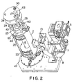
- Figure 2 is a perspective view with partial cutaway, of the plasma discharge device of Figure 1.
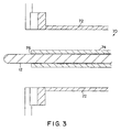
- Figure 3 shows the structure relating to the antenna configuration in greater detail.
- Figure 4 shows alternative structure relating to the antenna configuration.
- Figure 5 shows a slidable microwave trap.
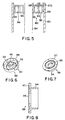
- Figures 6, 7 and 8 show components of the slidable trap.
- Figure 9 is a block diagram of a system for automatically adjusting the positions of the movable trap and the antenna.
- Figure 10 shows an embodiment of a microwave feed for a plasma discharge device.
- Referring to the Figures, longitudinally extending
cylindrical microwave cavity 2 is depicted, which has cylindrical plasma tube 4 running therethrough. The plasma tube may be made of quartz or sapphire, or other substance which is appropriate for the gas which is used. - In order to excite the gas flowing in plasma tube 4 to a plasma state, microwave excitation must be provided. To this end,
microwave source 6, e.g., a magnetron, generates microwave power which is fed throughdirectional coupler 7 to a waveguide having mutuallyperpendicular sections section 9 is controlled with moveable short 10, which may be a fixed rather than a moveable member if desired. Anantenna 12 in the form of a metallic rod is provided for coupling microwave power from the waveguide to the cavity via a waveguide to coaxial transition. The antenna extends through a circular opening in the cavity wall into the cavity, and its degree of insertion is adjustable. The adjustment is accomplished by pushing or pulling onmember 13 which is attached toantenna 12 with pin 15, thus causingantenna 12 to move in and out of the cavity.Member 13 is made of a low loss electrical insulator of low dielectric constant, e.g., polytetrafluorethylene, to prevent microwave leakage through the insertion hole. A screw mechanism including a stepping motor may be provided for automating the insertion and retraction of the antenna. As described above, the antenna adjustment allows the coupling of the field to the cavity to be optimized for specific operating conditions and increases the operating window of the system. - Figure 3 is a detail of
coaxial structure 70 shown in Figure 1. The coaxial structure is comprised ofouter conductor 72 and an inner conductor comprised ofsleeve 74 andantenna 12 which slides insleeve 74 with the aid of fingerstock contact ring 76. An altemative embodiment is shown in Figure 4, wherein like parts are identified with the same numerals. In Figure 4, coaxial structure 70' is comprised of outer conductor 72' and an inner conductor comprised of sleeve 74' and antenna 12' which slides therein. In the embodiment of Figure 4, the inner surface of outer conductor 72' and the outer surface of sleeve 74' are tapered so as to provide a gradual change in impedance, thereby providing better impedance matching between thewaveguide 9 and thecavity 2. - The ends of the microwave cavity are defined by
microwave traps - In accordance with an aspect of preferred embodiments the present invention, the longitudinal position of
microwave traps finger stock - Additionally, a screw mechanism may be provided for conveniently effecting the adjustment of the traps, and such a mechanism is shown in connection with the
top trap 20 in the Figures. It is comprised of horizontal (in the Figures)members cylindrical members members 23, (not all shown) which connect the top oftop trap 20 tomember 29. There are threemembers 65, (not all shown) which connect the top of the microwave cavity tomember 28, where they are secured with nuts 30 (only one shown).Member 60 is threaded, as is an opening inmember 29 through which in turn raises or lowers themicrowave trap 20. If desired a stepper motor may be employed in a configuration for automating the raising and lowering of the trap. A similar mechanism (not shown) can be employed for moving thebottom trap 22. - The adjustment of the cavity length provides a broad range of dynamic cavity tuning, and is what permits the device to be operated with different gasses over a wide range of process conditions. As is known to those skilled in the art, utilizing a different gas will change the load impedance and resonant frequency of the cavity, and effectively of the cavity, thereby detuning it. Re-tuning may be accomplished by experimenting with the positions of the slidable traps to establish a resonant TM012 mode in the cavity. That is, the cavity is nominally dimensioned to result in the TM012 mode, and the dynamic tuning permits resonance to be maintained over a variety of process gasses. In addition to the use of different gasses, a broad range of process conditions, e.g., gas flow, pressure, input power, etc. can be accommodated.
- While preferred embodiments of the invention are operable by making the position of only one trap adjustable, a big advantage is afforded when both traps are moveable. This is because the position of each trap may be independently changed in relation to the position of the antenna, thus affording a greater range of effective tuning.
- The device may be air cooled by providing a quartz tube close to and concentric with plasma tube 4, and feeding pressurized air in the space between the tubes, or if desired, may be liquid cooled with a high specific heat liquid that is microwave transparent and clean room friendly by feeding such substance between the concentric tubes.
- Referring to Figure 1, it is seen that
end cap 40 is provided which abuts the top of the cavity, while fitting 42 having a central orifice for admitting gas to the plasma tube extends into the end cap. The plasma tube is supported at this end byO ring 44 in the end cap.End member 46 is provided at the other end to provide the proper spacing in relation tobottom plate 47 and theprocess chamber 48, while this end of the plasma tube has an opening in it for emission into the process chamber. - In the operation of the device, oxygen, fluorine containing gas, or other gas is fed into
gas inlet 42, which feeds plasma tube 4. The microwave cavity is tuned to achieve a resonant TM012 mode by adjusting the position of slidable microwave traps 20 and 22, and matching of the cavity impedance with plasma to the characteristic impedance of the coaxial section is accomplished by adjusting the insertion ofantenna 12 into the cavity. A plasma is excited in the gas, the afterglow of which is emitted from an opening at the end of the plasma tube intoprocess chamber 48. While embodiments of the invention are applicable to devices where either the plasma or the afterglow from the plasma is used to remove material, the preferred embodiment is an afterglow device. - The TM012 field configuration is depicted in Figure 1 at
reference numeral 25. To prevent cracking of a sapphire plasma tube, it is necessary to prevent unequal heating of the tube, and a field configuration having azimuthal and longitudinal uniformity will accomplish this. The TM012 field has azimuthal uniformity (not shown), and as seen in Figure 1 also has adequate longitudinal uniformity. Thus, it has been found that use of the TM012 field configuration obviates cracking of the plasma tube, and as mentioned above, does not require a cavity which uses partitioning. - The
process chamber 48 includes retractable wafer support pins which supportwafer 54, to be processed. A chuck is arranged to provide the correct heating to the wafer during processing. One or more baffle plates may be present above the wafer to promote even distribution of the gas. - A disadvantage of the slidable microwave trap shown in Figure 1 is that it utilizes mechanical finger stock between it and the microwave cavity for enabling sliding motion. The finger stock may grind against the microwave cavity and create particles which could contaminate the processing, it may wear out and have to be replaced, and it may otherwise fail, so it is desirable to be able to eliminate it.
- This is what is accomplished in the embodiment depicted in Figure 5, wherein a particular sliding
trap 80 is utilized inmicrowave cavity 82 havingplasma tube 84. The trap is comprised ofmember 86, shown in perspective in Figure 6, andmember 88 shown in perspective in Figure 7, and in cross-section in Figure 8.Member 86 is seen to haveslits 90 andcircular groove 92.Member 88 is inserted in member 86 (see Figure 5), so thatcylindrical flange 94 ofmember 88 fits ingroove 92. - The structure is electrically two concentric microwave sub-traps, each of the type shown in Figure 1 and described in detail in U.S. Patent No. 5,498,308. Thus, the inner sub-trap, referring to Figure 5, which includes
cylinders gap 98 to zero, while the outer trap, comprised ofcylinders gap 100 to zero.Plasma tube 84 passes throughcentral openings members cylinders cylinders - Since the structure does not contact the microwave cavity, it is readily slidable therein, while effectively preventing microwave leakage.
- Turning to a further aspect of the invention, it is desirable for the respective positions of the moveable trap and antenna to be automatically adjusted to the best positions for any given process. The system which is shown in Figure 9 accomplish this.
- As previously mentioned, an advantage of the invention is that the dynamic tuning feature permits the device to be used over a wide range of specific processes. For each different process, e.g., different fill gas or gasses and/or power level, there is a unique adjustment of trap and antenna positions which provides optimum operation, i.e., minimum reflected power.
- Referring to Figure 9, look-up table 102 is provided, which may be in the form of a read only memory or software. The look-up table has programmed in it those values for trap and antenna positions which result in optimum operation. The data in look-up table 102 is established for each specific process by performing the following steps:
- a) selecting an antenna position and while the process is performed, moving the trap through a range of positions, and recording the reflected power for each combination of positions,
- b) moving the antenna position incrementally and again moving the trap through a range of positions and recording the reflected power for each combination of positions, and
- c) repeating step b) until the reflected power value for each incremental combination of trap and antenna position is determined. These values comprise the look-up table.
- In use of the system of Figure 9, an operator identifies the desired process to be performed to the
processor 104, which then accesses look-up table 102. The processor is programmed to select the combination of trap and antenna positions which has the minimum value of reflected power recorded against them for the particular process involved. Such information is fed back to the processor, which then controls trap stepping motor 106 andantenna stepping motor 108 to move the trap and antenna to the indicated positions. If there are a few combinations of trap - antenna positions which result in very low reflected power, i.e., less than 5%, the processor may be programmed to provide an indication of all such positions, so that each may be empirically tried. - Figure 10 shows an embodiment of a microwave feed for the plasma discharge device of the invention. Referring to the Figure, magnetron 110 is coupled to
circulator 112 and to waveguide 114 which drivesantenna 116.Directional coupler 118 is also provided, as is reflectedpower sensor 118. There is atwist 120 inwaveguide 114 to enable more compact packaging of the apparatus. - In an actual embodiment according to Figures 1 and 2, which was built, the magnetron frequency was 2443 Mhz, the microwave cavity had an internal diameter of 5.43 inches (13,8 cm) and was approximately 8.25 inches (21 cm) long with the microwave traps positioned to make the cavity as long as possible. The top microwave trap could be moved to shorten the cavity by about 3.5 inches (8,9 cm), while the bottom trap could be so moved by about .5 inch (1,3 cm). In use for removing polymeric residues, a plasma tube made of sapphire was used having an ID of 1.37 inches (3,48 cm) and a fluorine containing gas was flowed through the tube. The microwave power was about 2000 watts and the power density was about 11.8 watts/cc.
Claims (15)
- A dynamically tunable plasma discharge device for removing material from a substrate, comprising
a longitudinally extending microwave cavity,
a plasma tube passing through said microwave cavity for containing gas when in operation,
means for providing a microwave field in said cavity for exciting gas when in said plasma tube to a plasma, and
an opening in said plasma tube for permitting said gas to exit,
characterised in that
at least one end of said microwave cavity is defined by a microwave trap which reduces a microwave current to zero, the position of which is longitudinally adjustable to provide dynamic tuning of said cavity. - The device of claim 1 wherein both ends of said microwave cavity are defined by microwave traps and the respective positions of both microwave traps are longitudinally adjustable to provide dynamic tuning of said cavity.
- The device of claim 2 wherein said means for providing a microwave field in said cavity comprises microwave source means for providing microwave power and means for coupling said microwave power from said source means to said cavity, wherein said means for coupling includes an antenna which extends into said cavity, the degree of insertion of which into said cavity is adjustable.
- The device of any preceding claim wherein said gas may be selected from a plurality of gases including oxygen containing gas and fluorine containing gas.
- The device of any preceding claim further including means for utilizing said plasma or the afterglow therefrom to remove said material from said substrate.
- The device of any preceding claim wherein the microwave trap is moveable within the cavity along the length thereof, and causes the field between the trap and the cavity to be zero without the use of any physical member between the trap and the cavity.
- The device of claim 6 wherein the microwave trap is comprised of three concentric metallic cylindrical members.
- The device of claim 7 wherein the three concentric metallic cylindrical members comprise an inner cylindrical member, an outer cylindrical member, and an intermediate cylindrical member between the inner and outer members, and wherein the plasma tube passes through the inner cylindrical member.
- The device of claim 8 wherein the microwave trap causes the field between the plasma tube and the inner cylindrical member to be zero.
- The device of claim 9 wherein the inner and outer cylindrical members are parts of a first piece, while the intermediate cylindrical member is part of a second piece, wherein the second piece is inserted in the first piece.
- The device of claim 10 wherein the means for providing a microwave field in the cavity comprises microwave source means for providing microwave power and means for coupling the microwave power from the source means to the cavity, wherein the means for coupling includes an antenna which extends into the cavity, the degree of insertion of which into the cavity is adjustable.
- The device of any preceding claim wherein the means for providing a microwave field in the cavity provides a field having a resonant cylindrical TM012 mode.
- The device of claim 1, wherein the means for providing a microwave field in the cavity comprises microwave source means for providing microwave power and means for coupling the microwave power from the source means to the cavity, wherein the means for coupling includes an antenna which extends into the cavity, the degree of insertion of which into the cavity is adjustable, further including means for any selected material removal process, for automatically adjusting the respective positions of the microwave trap and the antenna such that the reflected microwave power is at a minimum.
- The device of claim 13 further including data storage means for storing data corresponding to microwave trap and antenna positions for various material removal processes.
- The device of claim 14 wherein the microwave trap is comprised of an inner cylindrical member, an outer cylindrical member, and an intermediate cylindrical member between the inner and outer cylindrical members, and wherein the plasma tube passes through the inner cylindrical member.
Applications Claiming Priority (3)
| Application Number | Priority Date | Filing Date | Title |
|---|---|---|---|
| US09/001,635 US6057645A (en) | 1997-12-31 | 1997-12-31 | Plasma discharge device with dynamic tuning by a movable microwave trap |
| US1635 | 1997-12-31 | ||
| PCT/US1998/027886 WO1999033673A1 (en) | 1997-12-31 | 1998-12-31 | Plasma discharge device and method with dynamic tuning |
Publications (3)
| Publication Number | Publication Date |
|---|---|
| EP1044113A1 EP1044113A1 (en) | 2000-10-18 |
| EP1044113A4 EP1044113A4 (en) | 2003-04-23 |
| EP1044113B1 true EP1044113B1 (en) | 2006-03-01 |
Family
ID=21697079
Family Applications (1)
| Application Number | Title | Priority Date | Filing Date |
|---|---|---|---|
| EP98966483A Expired - Lifetime EP1044113B1 (en) | 1997-12-31 | 1998-12-31 | Plasma discharge device and method with dynamic tuning |
Country Status (6)
| Country | Link |
|---|---|
| US (1) | US6057645A (en) |
| EP (1) | EP1044113B1 (en) |
| JP (1) | JP4362676B2 (en) |
| KR (1) | KR100544971B1 (en) |
| DE (1) | DE69833696T2 (en) |
| WO (1) | WO1999033673A1 (en) |
Families Citing this family (39)
| Publication number | Priority date | Publication date | Assignee | Title |
|---|---|---|---|---|
| DE19847848C1 (en) * | 1998-10-16 | 2000-05-11 | R3 T Gmbh Rapid Reactive Radic | Device and generation of excited / ionized particles in a plasma |
| JP2000133494A (en) | 1998-10-23 | 2000-05-12 | Mitsubishi Heavy Ind Ltd | Microwave plasma generation device and method |
| US6211621B1 (en) * | 1999-03-18 | 2001-04-03 | Gasonics International | Energy transfer microwave plasma source |
| US6263830B1 (en) * | 1999-04-12 | 2001-07-24 | Matrix Integrated Systems, Inc. | Microwave choke for remote plasma generator |
| US6607920B2 (en) | 2001-01-31 | 2003-08-19 | Cem Corporation | Attenuator system for microwave-assisted chemical synthesis |
| US6753517B2 (en) | 2001-01-31 | 2004-06-22 | Cem Corporation | Microwave-assisted chemical synthesis instrument with fixed tuning |
| US6886408B2 (en) * | 2001-01-31 | 2005-05-03 | Cem Corporation | Pressure measurement in microwave-assisted chemical synthesis |
| US6836060B2 (en) * | 2001-03-26 | 2004-12-28 | Agilent Technologies, Inc. | Air cooled gas discharge detector |
| US6761796B2 (en) * | 2001-04-06 | 2004-07-13 | Axcelis Technologies, Inc. | Method and apparatus for micro-jet enabled, low-energy ion generation transport in plasma processing |
| US6548416B2 (en) * | 2001-07-24 | 2003-04-15 | Axcelis Technolgoies, Inc. | Plasma ashing process |
| TW551782U (en) * | 2002-10-09 | 2003-09-01 | Ind Tech Res Inst | Microwave plasma processing device |
| US7144739B2 (en) * | 2002-11-26 | 2006-12-05 | Cem Corporation | Pressure measurement and relief for microwave-assisted chemical reactions |
| FR2847912B1 (en) * | 2002-11-28 | 2005-02-18 | Sidel Sa | METHOD AND DEVICE FOR PLASMA MICROWAVE DEPOSITION A COATING ON A SIDE OF A CONTAINER IN THERMOPLASTIC MATERIAL |
| US20040216845A1 (en) * | 2003-05-02 | 2004-11-04 | Czeslaw Golkowski | Non-thermal plasma generator device |
| US8580076B2 (en) * | 2003-05-22 | 2013-11-12 | Lam Research Corporation | Plasma apparatus, gas distribution assembly for a plasma apparatus and processes therewith |
| US7449416B2 (en) * | 2004-09-01 | 2008-11-11 | Axcelis Technologies, Inc. | Apparatus and plasma ashing process for increasing photoresist removal rate |
| US7338575B2 (en) * | 2004-09-10 | 2008-03-04 | Axcelis Technologies, Inc. | Hydrocarbon dielectric heat transfer fluids for microwave plasma generators |
| US20070228008A1 (en) * | 2004-12-06 | 2007-10-04 | University Of Houston | Medium pressure plasma system for removal of surface layers without substrate loss |
| JP4799947B2 (en) * | 2005-02-25 | 2011-10-26 | 株式会社ダイヘン | High frequency power supply device and control method of high frequency power supply |
| US7034266B1 (en) | 2005-04-27 | 2006-04-25 | Kimberly-Clark Worldwide, Inc. | Tunable microwave apparatus |
| JP2007227201A (en) * | 2006-02-24 | 2007-09-06 | Noritsu Koki Co Ltd | Plasma generator and work processing apparatus |
| KR101173268B1 (en) | 2007-03-29 | 2012-08-10 | 도쿄엘렉트론가부시키가이샤 | Plasma process apparatus |
| CN101632330B (en) * | 2007-06-11 | 2012-11-21 | 东京毅力科创株式会社 | Plasma processing apparatus, power supply apparatus and method for using plasma processing apparatus |
| WO2009008517A1 (en) * | 2007-07-12 | 2009-01-15 | Imagineering, Inc. | Controller of plasma formation region and plasma processor |
| US8316797B2 (en) | 2008-06-16 | 2012-11-27 | Board of Trustees of Michigan State University Fraunhofer USA | Microwave plasma reactors |
| EP2420113A4 (en) | 2009-04-14 | 2014-04-02 | Rf Thummim Technologies Inc | Method and apparatus for excitation of resonances in molecules |
| US8906195B2 (en) | 2009-11-18 | 2014-12-09 | Lam Research Corporation | Tuning hardware for plasma ashing apparatus and methods of use thereof |
| US9295968B2 (en) | 2010-03-17 | 2016-03-29 | Rf Thummim Technologies, Inc. | Method and apparatus for electromagnetically producing a disturbance in a medium with simultaneous resonance of acoustic waves created by the disturbance |
| US9129778B2 (en) | 2011-03-18 | 2015-09-08 | Lam Research Corporation | Fluid distribution members and/or assemblies |
| EP2707521B1 (en) | 2011-05-13 | 2018-08-08 | Board Of Trustees Of Michigan State University | Improved microwave plasma reactors |
| JP5368514B2 (en) * | 2011-06-30 | 2013-12-18 | 東京エレクトロン株式会社 | Plasma processing equipment |
| US9396955B2 (en) * | 2011-09-30 | 2016-07-19 | Tokyo Electron Limited | Plasma tuning rods in microwave resonator processing systems |
| US9763287B2 (en) * | 2011-11-30 | 2017-09-12 | Michael R. Knox | Single mode microwave device for producing exfoliated graphite |
| JP5725574B2 (en) * | 2013-03-05 | 2015-05-27 | 東京エレクトロン株式会社 | Microwave waveguide device, plasma processing apparatus, and plasma processing method |
| WO2015069905A1 (en) * | 2013-11-06 | 2015-05-14 | Tokyo Electron Limited | Multi-cell resonator microwave surface-wave plasma apparatus |
| NL2017575B1 (en) | 2016-10-04 | 2018-04-13 | Draka Comteq Bv | A method and an apparatus for performing a plasma chemical vapour deposition process and a method |
| CN105979693A (en) * | 2016-06-12 | 2016-09-28 | 浙江大学 | High-power microwave plasma generation device |
| AT523626B1 (en) * | 2020-05-22 | 2021-10-15 | Anton Paar Gmbh | Waveguide coupling unit |
| CN111690913B (en) * | 2020-07-22 | 2023-06-23 | 中南大学 | A microwave shielding tube and magnetic field enhanced flat PECVD equipment |
Family Cites Families (21)
| Publication number | Priority date | Publication date | Assignee | Title |
|---|---|---|---|---|
| US3577207A (en) * | 1969-05-07 | 1971-05-04 | Vladimir Pavlovich Kirjushin | Microwave plasmatron |
| JPS5939178B2 (en) * | 1977-04-25 | 1984-09-21 | 株式会社東芝 | Activated gas generator |
| FR2533397A2 (en) * | 1982-09-16 | 1984-03-23 | Anvar | IMPROVEMENTS IN PLASMA TORCHES |
| US4691662A (en) * | 1983-02-28 | 1987-09-08 | Michigan State University | Dual plasma microwave apparatus and method for treating a surface |
| US4507588A (en) * | 1983-02-28 | 1985-03-26 | Board Of Trustees Operating Michigan State University | Ion generating apparatus and method for the use thereof |
| US4630566A (en) * | 1984-08-16 | 1986-12-23 | Board Of Trustees Operating Michigan State University | Microwave or UHF plasma improved apparatus |
| US4866346A (en) * | 1987-06-22 | 1989-09-12 | Applied Science & Technology, Inc. | Microwave plasma generator |
| JPH01198478A (en) * | 1988-02-01 | 1989-08-10 | Canon Inc | Microwave plasma cvd device |
| JPH01297141A (en) * | 1988-05-25 | 1989-11-30 | Canon Inc | Microwave plasma processing device |
| JPH02107778A (en) * | 1988-10-18 | 1990-04-19 | Canon Inc | Polarization control microwave plasma processing equipment |
| US5201994A (en) * | 1988-11-18 | 1993-04-13 | Kabushiki Kaisha Tokuda Seisakusho | Dry etching method |
| US4943345A (en) * | 1989-03-23 | 1990-07-24 | Board Of Trustees Operating Michigan State University | Plasma reactor apparatus and method for treating a substrate |
| FR2647293B1 (en) * | 1989-05-18 | 1996-06-28 | Defitech Sa | IMPROVED PLASMA REACTOR PROVIDED WITH ELECTROMAGNETIC WAVE COUPLING MEANS |
| JP2922223B2 (en) * | 1989-09-08 | 1999-07-19 | 株式会社日立製作所 | Microwave plasma generator |
| US5082517A (en) * | 1990-08-23 | 1992-01-21 | Texas Instruments Incorporated | Plasma density controller for semiconductor device processing equipment |
| US5262610A (en) * | 1991-03-29 | 1993-11-16 | The United States Of America As Represented By The Air Force | Low particulate reliability enhanced remote microwave plasma discharge device |
| DE4132558C1 (en) * | 1991-09-30 | 1992-12-03 | Secon Halbleiterproduktionsgeraete Ges.M.B.H., Wien, At | |
| US5389153A (en) * | 1993-02-19 | 1995-02-14 | Texas Instruments Incorporated | Plasma processing system using surface wave plasma generating apparatus and method |
| FR2702328B1 (en) * | 1993-03-05 | 1995-05-12 | Univ Lille Sciences Tech | Device for producing a plasma. |
| US5498308A (en) * | 1994-02-25 | 1996-03-12 | Fusion Systems Corp. | Plasma asher with microwave trap |
| US5961851A (en) * | 1996-04-02 | 1999-10-05 | Fusion Systems Corporation | Microwave plasma discharge device |
-
1997
- 1997-12-31 US US09/001,635 patent/US6057645A/en not_active Expired - Lifetime
-
1998
- 1998-12-31 KR KR1020007007351A patent/KR100544971B1/en not_active Expired - Fee Related
- 1998-12-31 WO PCT/US1998/027886 patent/WO1999033673A1/en not_active Ceased
- 1998-12-31 EP EP98966483A patent/EP1044113B1/en not_active Expired - Lifetime
- 1998-12-31 JP JP2000526382A patent/JP4362676B2/en not_active Expired - Fee Related
- 1998-12-31 DE DE69833696T patent/DE69833696T2/en not_active Expired - Fee Related
Also Published As
| Publication number | Publication date |
|---|---|
| EP1044113A4 (en) | 2003-04-23 |
| DE69833696D1 (en) | 2006-04-27 |
| US6057645A (en) | 2000-05-02 |
| JP2001527300A (en) | 2001-12-25 |
| JP4362676B2 (en) | 2009-11-11 |
| KR100544971B1 (en) | 2006-01-24 |
| WO1999033673A1 (en) | 1999-07-08 |
| EP1044113A1 (en) | 2000-10-18 |
| KR20010033802A (en) | 2001-04-25 |
| DE69833696T2 (en) | 2006-11-16 |
Similar Documents
| Publication | Publication Date | Title |
|---|---|---|
| KR100544971B1 (en) | Plasma emitting device and method with dynamic tuning | |
| US5961851A (en) | Microwave plasma discharge device | |
| KR101560122B1 (en) | Surface wave plasma processing apparatus | |
| EP0395798A2 (en) | Microwave resonant cavity | |
| EP1177112B1 (en) | Remote plasma generator | |
| US20110036500A1 (en) | Wide area radio frequency plasma apparatus for processing multiple substrates | |
| EP0791949A2 (en) | Plasma processing method and apparatus | |
| JPH06295797A (en) | Generator of plasma and method of occurrence | |
| US7163603B2 (en) | Plasma source assembly and method of manufacture | |
| US6046545A (en) | Light source apparatus using coaxial waveguide | |
| US20040069232A1 (en) | Microwave plasma processing apparatus | |
| US4611121A (en) | Magnet apparatus | |
| EP0776073A1 (en) | Rectangular discharge gas laser | |
| JP3215461B2 (en) | Microwave excitation type ultraviolet lamp device | |
| US12463013B2 (en) | Plasma processing apparatus | |
| US5641359A (en) | Process gas delivery system | |
| JPS629686A (en) | gas laser equipment | |
| KR100500360B1 (en) | High efficient-atmospheric microwave plasma system | |
| Bilida et al. | Multi-channel slab CO2 laser excitation with resonant cavities | |
| US6211621B1 (en) | Energy transfer microwave plasma source | |
| JP2006130385A (en) | Microwave chemical reactor | |
| JPH1012594A (en) | Plasma processing apparatus having slot antenna | |
| US20250104972A1 (en) | Plasma Source and Plasma Processing Apparatus | |
| CA2465932A1 (en) | Microwave applicator system | |
| JPH10208899A (en) | Plasma processing equipment |
Legal Events
| Date | Code | Title | Description |
|---|---|---|---|
| PUAI | Public reference made under article 153(3) epc to a published international application that has entered the european phase |
Free format text: ORIGINAL CODE: 0009012 |
|
| 17P | Request for examination filed |
Effective date: 20000724 |
|
| AK | Designated contracting states |
Kind code of ref document: A1 Designated state(s): DE FR GB IT NL |
|
| A4 | Supplementary search report drawn up and despatched |
Effective date: 20030306 |
|
| RIC1 | Information provided on ipc code assigned before grant |
Ipc: 7H 01J 37/32 B Ipc: 7B 44C 1/22 A |
|
| 17Q | First examination report despatched |
Effective date: 20040608 |
|
| GRAP | Despatch of communication of intention to grant a patent |
Free format text: ORIGINAL CODE: EPIDOSNIGR1 |
|
| GRAS | Grant fee paid |
Free format text: ORIGINAL CODE: EPIDOSNIGR3 |
|
| GRAA | (expected) grant |
Free format text: ORIGINAL CODE: 0009210 |
|
| AK | Designated contracting states |
Kind code of ref document: B1 Designated state(s): DE FR GB IT NL |
|
| PG25 | Lapsed in a contracting state [announced via postgrant information from national office to epo] |
Ref country code: NL Free format text: LAPSE BECAUSE OF FAILURE TO SUBMIT A TRANSLATION OF THE DESCRIPTION OR TO PAY THE FEE WITHIN THE PRESCRIBED TIME-LIMIT Effective date: 20060301 Ref country code: IT Free format text: LAPSE BECAUSE OF FAILURE TO SUBMIT A TRANSLATION OF THE DESCRIPTION OR TO PAY THE FEE WITHIN THE PRESCRIBED TIME-LIMIT;WARNING: LAPSES OF ITALIAN PATENTS WITH EFFECTIVE DATE BEFORE 2007 MAY HAVE OCCURRED AT ANY TIME BEFORE 2007. THE CORRECT EFFECTIVE DATE MAY BE DIFFERENT FROM THE ONE RECORDED. Effective date: 20060301 |
|
| REG | Reference to a national code |
Ref country code: GB Ref legal event code: FG4D |
|
| REF | Corresponds to: |
Ref document number: 69833696 Country of ref document: DE Date of ref document: 20060427 Kind code of ref document: P |
|
| NLV1 | Nl: lapsed or annulled due to failure to fulfill the requirements of art. 29p and 29m of the patents act | ||
| ET | Fr: translation filed | ||
| PLBE | No opposition filed within time limit |
Free format text: ORIGINAL CODE: 0009261 |
|
| STAA | Information on the status of an ep patent application or granted ep patent |
Free format text: STATUS: NO OPPOSITION FILED WITHIN TIME LIMIT |
|
| 26N | No opposition filed |
Effective date: 20061204 |
|
| PGFP | Annual fee paid to national office [announced via postgrant information from national office to epo] |
Ref country code: FR Payment date: 20081205 Year of fee payment: 11 |
|
| PGFP | Annual fee paid to national office [announced via postgrant information from national office to epo] |
Ref country code: DE Payment date: 20081230 Year of fee payment: 11 |
|
| PGFP | Annual fee paid to national office [announced via postgrant information from national office to epo] |
Ref country code: GB Payment date: 20081110 Year of fee payment: 11 |
|
| GBPC | Gb: european patent ceased through non-payment of renewal fee |
Effective date: 20091231 |
|
| REG | Reference to a national code |
Ref country code: FR Ref legal event code: ST Effective date: 20100831 |
|
| PG25 | Lapsed in a contracting state [announced via postgrant information from national office to epo] |
Ref country code: FR Free format text: LAPSE BECAUSE OF NON-PAYMENT OF DUE FEES Effective date: 20091231 |
|
| PG25 | Lapsed in a contracting state [announced via postgrant information from national office to epo] |
Ref country code: DE Free format text: LAPSE BECAUSE OF NON-PAYMENT OF DUE FEES Effective date: 20100701 |
|
| PG25 | Lapsed in a contracting state [announced via postgrant information from national office to epo] |
Ref country code: GB Free format text: LAPSE BECAUSE OF NON-PAYMENT OF DUE FEES Effective date: 20091231 |