EP1044080B1 - Ceramic cutting insert - Google Patents
Ceramic cutting insert Download PDFInfo
- Publication number
- EP1044080B1 EP1044080B1 EP98962773A EP98962773A EP1044080B1 EP 1044080 B1 EP1044080 B1 EP 1044080B1 EP 98962773 A EP98962773 A EP 98962773A EP 98962773 A EP98962773 A EP 98962773A EP 1044080 B1 EP1044080 B1 EP 1044080B1
- Authority
- EP
- European Patent Office
- Prior art keywords
- cutting insert
- clamp
- insert
- cutting
- inner cavity
- Prior art date
- Legal status (The legal status is an assumption and is not a legal conclusion. Google has not performed a legal analysis and makes no representation as to the accuracy of the status listed.)
- Expired - Lifetime
Links
Images

Classifications
-
- B—PERFORMING OPERATIONS; TRANSPORTING
- B23—MACHINE TOOLS; METAL-WORKING NOT OTHERWISE PROVIDED FOR
- B23B—TURNING; BORING
- B23B27/00—Tools for turning or boring machines; Tools of a similar kind in general; Accessories therefor
- B23B27/14—Cutting tools of which the bits or tips or cutting inserts are of special material
- B23B27/16—Cutting tools of which the bits or tips or cutting inserts are of special material with exchangeable cutting bits or cutting inserts, e.g. able to be clamped
- B23B27/1644—Cutting tools of which the bits or tips or cutting inserts are of special material with exchangeable cutting bits or cutting inserts, e.g. able to be clamped with plate-like cutting inserts of special shape clamped by a clamping member acting almost perpendicularly on the chip-forming plane and at the same time upon the wall of a hole in the cutting insert
- B23B27/1651—Cutting tools of which the bits or tips or cutting inserts are of special material with exchangeable cutting bits or cutting inserts, e.g. able to be clamped with plate-like cutting inserts of special shape clamped by a clamping member acting almost perpendicularly on the chip-forming plane and at the same time upon the wall of a hole in the cutting insert characterised by having a special shape
-
- B—PERFORMING OPERATIONS; TRANSPORTING
- B23—MACHINE TOOLS; METAL-WORKING NOT OTHERWISE PROVIDED FOR
- B23B—TURNING; BORING
- B23B2205/00—Fixation of cutting inserts in holders
- B23B2205/16—Shims
-
- B—PERFORMING OPERATIONS; TRANSPORTING
- B23—MACHINE TOOLS; METAL-WORKING NOT OTHERWISE PROVIDED FOR
- B23B—TURNING; BORING
- B23B2226/00—Materials of tools or workpieces not comprising a metal
- B23B2226/18—Ceramic
-
- Y—GENERAL TAGGING OF NEW TECHNOLOGICAL DEVELOPMENTS; GENERAL TAGGING OF CROSS-SECTIONAL TECHNOLOGIES SPANNING OVER SEVERAL SECTIONS OF THE IPC; TECHNICAL SUBJECTS COVERED BY FORMER USPC CROSS-REFERENCE ART COLLECTIONS [XRACs] AND DIGESTS
- Y10—TECHNICAL SUBJECTS COVERED BY FORMER USPC
- Y10T—TECHNICAL SUBJECTS COVERED BY FORMER US CLASSIFICATION
- Y10T407/00—Cutters, for shaping
- Y10T407/22—Cutters, for shaping including holder having seat for inserted tool
- Y10T407/2272—Cutters, for shaping including holder having seat for inserted tool with separate means to fasten tool to holder
- Y10T407/2274—Apertured tool
Landscapes
- Engineering & Computer Science (AREA)
- Mechanical Engineering (AREA)
- Cutting Tools, Boring Holders, And Turrets (AREA)
- Drilling Tools (AREA)
- Ceramic Products (AREA)
- Processing Of Stones Or Stones Resemblance Materials (AREA)
Abstract
Description
- The present invention relates to a ceramic cutting insert for a cutting tool of the type which comprises a tool holder with a seat intended to accept the cutting insert, the shape of which partially corresponds to that of the cutting insert, and a clamp which is connected to the holder via a screw the object of which is to clamp the cutting insert firmly in the seat, said clamp features a nose provided to grip into one of the two recessed openings on opposite upper and lower sides on the cutting insert so that when the screw is tightened the cutting insert is drawn into the seat so that at least one side surface of the insert is tightly pressed against a corresponding side surface of the seat.
- A cutting tool, including a cutting insert and a tool holder in general of the type described above, is earlier known through SE 9401822-3. In this case the recess in the cutting insert has the form of a transverse, cylindrical hole, which like the nose of the clamp is generally cylindrical in shape, although inclined in relationship to the cylindrical hole in the cutting insert. The length of the nose is relatively large, whereby the point of contact between the nose and the cylindrically shaped inner wall of the hole is located relatively far down in the hole. This cutting tool has been found to work largely without problems in practical use.
- Another cutting tool, of the type generally indicated in the preamble, is known from EP 0 074 601. In this case the recess in the cutting insert has the shape of an comparatively shallow recess with a basic shape of either a four leaf clover or a figure of eight, at the same time the nose of the clamp has a half cylindrical or half barrel like shape, whereby the longitudinal extension of the nose is oriented at right angles to the actual longitudinal extension of the clamp. Through this design a point contact is attained between the nose and the inside surface of the recess. A drawback with this design, however, is that the longitudinal extension of the clamp must always be located in the direction of the bisector between diametrically opposite comers on a quadrilateral shaped cutting insert, e.g. a square or rhombic shaped insert. For this reason cutting tools of this type are difficult to use in machines where two or more cutting inserts are to be placed near each other.
- Another cutting tool, of the type generally indicated in the preamble, is known from EP 0 901995. In this case the recesses in the top and bottom surfaces of the cutting insert have the shape of inverted cones with flat or rounded bottoms. A drawback with this design, however, is that the nose of the clamp locates against an angled surface giving a reduced contact surface.
- Irrespective of the type of tool the cutting insert is always a replaceable component with a limited life, whilst the tool holder is of a more long-lived character. In practice therefore the cutting insert can thus have an effective life of some few hours, whilst the life of the tool holder can extend to months or years. Cutting tools are to be found on the market belonging to both the first mentioned and the latter type but not only in such a way that different users use different types of tools but also in such a way that one and the same user or machine owner can have both types of tools. This fact entails both organizational as well as logistical problems as far as the supply of cutting inserts for tools must be arranged via different channels since the cutting inserts are specially designed to fit the different tool types individually.
- The aim of the present invention is to solve the above-mentioned problem by creating a new cutting insert for both types of tool. A basic purpose of the present invention is thus to create a ceramic insert which can be used universally for cutting tools according to both SE 9401822-3 and EP 0 074 601 and which furthermore permits the use of variable adjustments of the angular position of the clamp relative to the insert even in those cases when the tool is of the type which is described in EP 0 074 601. An additional purpose is to create a ceramic insert, which lends itself to an easy and economic method of manufacture despite the fact of its ability to fit into both types of tool.
- At least the main aim of the invention is achieved by the features of the invention, which are described in the "characterized in" part of
claim 1. A further advantageous embodiment of the invention is given in thedependent claim 2. - The drawings are comprised of:
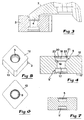
- Fig 1
- a partial longitudinal section (A-A in fig 2) through a tool according to SE 9401822-3, but with a cutting insert according to an embodiment of the invention,
- Fig 2
- a plan view from above of the clamp of the tool and the cutting insert according to an embodiment of the invention,
- Fig 3
- a longitudinal section through only the actual clamp and a cutting insert according to an embodiment of the invention co-operating therewith,
- Fig 4
- an enlarged longitudinal section through the cutting insert according to an embodiment of the invention,
- Fig 5
- a perspective view of the same cutting insert according to an embodiment of the invention,
- Fig 6
- a plan view of the cutting insert according to an embodiment of the invention,
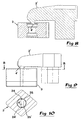
- Fig 7
- a longitudinal section through an alternative embodiment of the cutting insert according to an embodiment of the invention,
- Fig 8
- a schematic longitudinal section through a clamp to the tool according to EP 0 074 601 in co-operation with the cutting insert according to an embodiment of the invention,
- Fig 9
- a schematic side view of the clamp and the cutting insert according to fig 8,
- Fig 10
- a planar section (B-B in fig 9) through the cutting insert according to an embodiment of the invention alone,
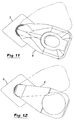
- Fig 11
- a planar view illustrating how the clamp on the tool according to SE 9401822-3 can be installed in different angles relative to the insert according to an embodiment of the invention, and
- Fig 12
- a corresponding planar view showing also how the clamp on the tool according to EP 0 074 601 in analogous manner allows itself to be oriented in different positions relative to the cutting insert according to an embodiment of the invention.
- The cutting tool produced according to SE 9401822-3 as illustrated in fig 1 and 2 includes three main components, that is to say a
holder 1, aclamp 2 as well as acutting insert 3 according to an embodiment of the invention. Thecutting insert 3 is produced in a ceramic material, whilst the holder and clamp are customarily made of steel. Theclamp 2 has an elongated basic shape and features at an external, free end anose 4 which has as its function to lock into a recess, which is designated 5, in thecutting insert 3. This nose has a cylindrical basic shape, however the nose is inclined relative to the longitudinal or centre axis of the recess. The clamp is linked to theholder 1 via a screw 6 which can be screwed down into a threadedhole 7 in the holder, more exactly against the effect of a spring 8 which strives to lift the clamp towards an outer position. Apin 9, which acts as a stop ensures that the clamp does not twist itself as the screw is tightened. In the region of its rear end the clamp features aninclined surface 10 which abuts against asurface 11 on theholder 1 which is inclined in a similar manner. Through co-operation between thesesurfaces nose 4 is not only pressed in a downwards direction but it also moves in a rearward direction in order to draw thecutting insert 3 into a seat in theholder 1. - Said seat has a shape, which partially corresponds to that of the cutting insert, however this is not illustrated in the drawings. In the example given according to fig 1-2 the
cutting insert 3 has a polygonal, more specifically a rhombic basic shape, wherein same is delimited by planar upper andlower sides 12, 12' plus fourside faces 13. In this connection however it should be pointed out that the insert may have whatever arbitrary basic form, for example square or circular. The example also shows how ashim 14 may be introduced between thecutting insert 3 and thebottom 15 of the insert pocket. This shim is held in place with the help of ascrew 16. - As far as the illustrated cutting tool has been described so far it is the same in all significant features as has been known earlier from SE 9401822-3.
- Now reference is made to figs 3-6, which illustrate in more detail a first embodiment of the cutting insert according to the invention. Hereby the invention is thought to be applied in connection with an indexable cutting insert. For this reason the cutting insert includes two
opposite recesses 5, 5' designed to receive thenose 4 of theclamp finger 2.Recesses 5, 5' are diametrically opposite each other, in addition anopen channel 17 extends between them. - Characteristic for the cutting insert according to the invention is that the
individual recesses 5, 5' have a rotationally symmetrical shape and comprise partly aninner cavity 18 which is delimited by a cylindrical or slightlyconical surface 19, partly anexternal cavity 20 which extends from the far end of the inner cavity and expands outwards by ever increasing its diameter in the direction from the inner cavity to the entrance opening in the upper surface 12 (respectively the bottom side 12') of the cutting insert. Theexternal cavity 20 is delimited by at least two ring-shaped partial surfaces, namely a first,conical surface portion 21 and a second, convex dome-shapedsurface portion 22, which extends between theinner cavity 18 andconical surface 21. In the particularly preferred embodiment which is shown in the drawings theexternal cavity 20 is delimited also by athird surface portion 23 in the shape of an convex dome-shaped surface portion which extends between theconical surface 21 and the planar upper surface 12 (respectively the bottom surface 12') on the cutting insert. - As is distinctly shown in fig 3 the comparatively
long nose 4 on theclamp finger 2 will come to abut against theinner surface wall 19 of thecavity 18 when achieving point or linear contact between the nose and surface wall. Hereby a distinct and reliable transfer of the required forces from the clamping finger and nose to the insert is attained in connection with the insert being drawn into its corresponding seat in the tool holder. - The alternative embodiment of the cutting insert, which is shown in fig 7, differs from the cutting insert described above only in that the
transverse channel 17 is lacking. In this manner the tworecesses 5, 5' are separated by a central portion of material. This means that the cutting insert - for a given dimension - contains more material and thereby has greater strength. - Now reference is made to fig 8-10 which illustrates schematically a clamp of the type which is part of the cutting tool according TO EP 0 074 601. Basically this clamp differs from the clamps shown in figs 1 and 3 only in that the nose 4' has a half cylindrical or half barrel like shape. As is shown fig 10 the nose is long and narrow and extends with its longside at right angles to the clamp's 2'longside. The opposed side faces 24,24' on the nose narrow off not only in the forward direction, as is shown in fig 10, but also in the downwards direction (which is not apparent from fig 10).
- When the nose 4' is brought to engage in the
recess 5 of the cutting insert and the screw of the clamp is tightened point contact is obtained, more exactly at twopoints 25, 25' between the nose and at least one of the partial surfaces which delimits theouter cavity 20 of the recess. More exactly two point contact will occur against the conicalpartial surface 21 or the dome-shapedpartial surface 22 which exist between the conical surface and thewall surface 19 which delimits theinner cavity 18; all being dependent on the condition of the nose regarding, for example, the degree of wear. Even in this case a distinct pressing of the nose against the inside of the recess is attained, namely against the said partial surfaces in the external cavity. Since the cavity has a rotationally symmetrical shape it is ensured that the said point contact is attained irrespective of the clamp's angular position relative to the insert. This is clearly shown in fig 12 which illustrates how the clamp 2' can be installed in different positions in relation to the cutting insert (and vice versa). The only purpose of fig 11 is to clarify that the same variation of the angular position can happen atclamp 2 according to SE 9401822-3. - The cutting insert according to the invention can be manufactured in different versions with mutually different dimensions. In practice the cutting insert can have a thickness of the magnitude of 5-7 mm. Generally the diameter of the
inner cavity 18 varies in accordance with the thickness of the insert. If the cutting insert is thin this diameter can be of the order of up to 3,8 mm, whilst the same diameter for the thickest the cutting insert can be up to 6,5 mm. In a medium thick t embodiment the diameter of thecavity 18 can be up to about 5 mm. Further the depth of thecavity 18 can vary in accordance with the dimensions of the cutting insert. In a medium thick cutting insert with a diameter of 5 mm can the depth of thecavity 18 be of the order of 0,8-1,2 mm, preferably about 1 mm. Even the depth of theexternal cavity 20 can vary, as can also the depths of the separatepartial surfaces external cavity 20 can have a total depth of the magnitude of 0,8-1,5 mm, suitably 1,0-1,3 mm. Both thepartial surfaces partial surface 21, has a shallower depth, e.g. in the range of 0,25-0,5 mm, suitably 0,3-0,4 mm. In practice the total depth for the differentpartial surfaces inner cavity 18. - Regarding the
conical surface 21 it should be pointed out that the angle of the cone could lie in the range of 35-55°. However the lower limit can be larger than 35°, e.g. 40° or 42°. In an analogous manner the upper limit can be less than 55°, e.g. 50° or 48°. In practice a cone angle of 45-46° is preferred. - The radius of curvature of the external dome-shaped
partial surface 23 can amount to about 1 mm, whilst the radius of curvature of the inner dome-shapedpartial surface 22 can lie in the range of 0,7-1,0 mm. - A significant advantage with the cutting insert according to the invention is that the insert can be used universally in cutting tools according to both SE 9401822-3 and EP 0 074 601. To make doubly sure, the cutting insert furthermore allows the clamp to be angled relative to the bisector of a polygonal or square cutting insert; something which is not possible when using inserts according to EP 0 074 601. This means that machine owners who use both types of cutting tool can use one and the same cutting insert throughout and in this manner avoid costly difficulties with regard to tool stocks and other organizational problems in connection with the supply of cutting inserts for the tools.
Claims (2)
- Ceramic cutting insert for a cutting tool of the type which comprises a holder (1) with an insert seat intended for the acceptance of the cutting insert (3) the shape of which partially corresponds to the shape of the cutting insert, and a clamp (2) which is connected to the holder via a screw (6) the function of which is to firmly clamp the cutting insert in the seat, said clamp (2) features a nose (4) provided to grip into one of two recesses (5) which have their openings on opposite upper and lower sides (12, 12') on the cutting insert in order to pull the cutting insert into the insert seat and press tightly at least one side surface of the cutting insert against a corresponding side surface in the insert seat when the screw (6) is tightened, characterized in that, the recess (5) has a rotational symmetrical shape and comprises an inner cavity (18) which is delimited by a cylindrical or slightly conical wall surface (19) and an external cavity (20) which extends from the far end of the inner cavity and expands outwards by ever increasing its diameter in the direction from the inner cavity to the entrance opening in said upper or lower sides (12, 12') and that the external cavity (20) is delimited by at least two ring shaped partial surfaces, namely a first, conical partial surface (21) and a second, convex dome-shaped partial surface (22) which extends between the inner cavity (18) and the conical surface (21).
- Ceramic cutting insert according to claims 1,
characterized in that, the external cavity (20) besides the said first and second partial surfaces (21, 22) is also delimited by a third, convex dome shaped partial surface (23) which extends between the conical surface (21) and said upper or lower side (12, 12') on the cutting insert.
Applications Claiming Priority (3)
| Application Number | Priority Date | Filing Date | Title |
|---|---|---|---|
| SE9704482A SE512860C2 (en) | 1997-12-03 | 1997-12-03 | ceramic Cutting |
| SE9704482 | 1997-12-03 | ||
| PCT/SE1998/002220 WO1999030860A1 (en) | 1997-12-03 | 1998-12-03 | Ceramic cutting insert |
Publications (2)
| Publication Number | Publication Date |
|---|---|
| EP1044080A1 EP1044080A1 (en) | 2000-10-18 |
| EP1044080B1 true EP1044080B1 (en) | 2003-03-05 |
Family
ID=20409226
Family Applications (1)
| Application Number | Title | Priority Date | Filing Date |
|---|---|---|---|
| EP98962773A Expired - Lifetime EP1044080B1 (en) | 1997-12-03 | 1998-12-03 | Ceramic cutting insert |
Country Status (9)
| Country | Link |
|---|---|
| US (1) | US6609859B1 (en) |
| EP (1) | EP1044080B1 (en) |
| JP (1) | JP2002508260A (en) |
| KR (1) | KR100599945B1 (en) |
| CN (1) | CN1105610C (en) |
| AT (1) | ATE233628T1 (en) |
| DE (1) | DE69811953T2 (en) |
| SE (1) | SE512860C2 (en) |
| WO (1) | WO1999030860A1 (en) |
Families Citing this family (12)
| Publication number | Priority date | Publication date | Assignee | Title |
|---|---|---|---|---|
| US6540450B2 (en) * | 2000-11-29 | 2003-04-01 | Hayes Lemmerz International, Inc. | Tool and process for finishing a vehicle wheel surface |
| US6893330B2 (en) * | 2000-11-08 | 2005-05-17 | Hayes Lemmerz International, Inc. | Tool and process for chrome plating a vehicle wheel surface |
| US6997787B2 (en) * | 2000-11-08 | 2006-02-14 | Hayes Lemmerz International, Inc. | Process for copper free chrome plating of a vehicle wheel surface |
| DE10142049A1 (en) | 2001-08-28 | 2003-03-20 | Kennametal Inc | Cutting insert and its use |
| DE10239451A1 (en) * | 2002-08-28 | 2004-03-11 | Ceramtec Ag Innovative Ceramic Engineering | Cutting plate for mounting in a cutting tool for cutting cast material, especially cast iron, comprises a cutting plate upper side, a cutting edge |
| US7547163B2 (en) * | 2007-07-16 | 2009-06-16 | Kennametal Inc. | Clamping tool holder |
| US8491230B2 (en) * | 2007-08-10 | 2013-07-23 | Taegutec, Ltd. | Clamping device for a cutting insert |
| US8057131B2 (en) * | 2009-01-17 | 2011-11-15 | Kennametal Inc. | Clamping tool holder |
| DE112011100336A5 (en) * | 2010-01-26 | 2012-11-22 | Ferroll Gmbh | CUTTING PLATE FOR INTERIOR FINISHING OF METALLIC TUBES AND ASSOCIATED PUNCHING CUTTING DEVICE AND WORKPIECE |
| DK2763809T3 (en) * | 2011-10-06 | 2020-09-07 | Ceram Gmbh | MINIATURE CUTTING PLATE |
| EP2792438B1 (en) * | 2011-12-15 | 2018-04-04 | Tungaloy Corporation | Clamp mechanism, cutting insert and clamp member |
| US20160016233A1 (en) * | 2014-07-17 | 2016-01-21 | Kennametal India Limited | Notched cutting inserts and applications thereof |
Citations (1)
| Publication number | Priority date | Publication date | Assignee | Title |
|---|---|---|---|---|
| EP0901995A2 (en) * | 1997-09-09 | 1999-03-17 | Sumitomo Electric Industries, Ltd. | Ceramic insert for use with clamp type cutting tool |
Family Cites Families (15)
| Publication number | Priority date | Publication date | Assignee | Title |
|---|---|---|---|---|
| US3662444A (en) * | 1970-03-09 | 1972-05-16 | Ingersoll Milling Machine Co | Indexable cutting insert and holder therefor |
| SE424273B (en) * | 1980-11-17 | 1982-07-12 | Sandvik Ab | MADE TOOLS |
| DE3136502A1 (en) * | 1981-09-15 | 1983-03-31 | Feldmühle AG, 4000 Düsseldorf | CUTTING TOOL |
| GB2116081A (en) * | 1982-02-26 | 1983-09-21 | Gen Electric | Inserts for cutting tools |
| US4697963A (en) | 1985-02-08 | 1987-10-06 | Ingersoll Cutting Tool Company | Insert clamping device and insert therefor |
| US4615650A (en) * | 1985-10-15 | 1986-10-07 | Gte Valeron Corporation | Locking pin for a tool holder |
| JPH0825088B2 (en) * | 1988-06-10 | 1996-03-13 | 東芝タンガロイ株式会社 | Indexable inserts for face milling |
| US4963061A (en) * | 1989-04-07 | 1990-10-16 | Gte Valenite Corporation | Ceramic cutting insert |
| EP0458003B1 (en) * | 1990-05-22 | 1995-02-15 | Seco Tools Ab | Cutting insert |
| US5141367A (en) * | 1990-12-18 | 1992-08-25 | Kennametal, Inc. | Ceramic cutting tool with chip control |
| JP2833283B2 (en) * | 1991-09-05 | 1998-12-09 | 三菱マテリアル株式会社 | Indexable tip |
| DE4209084A1 (en) * | 1992-03-20 | 1993-09-23 | Neumo Grundbesitz Gmbh | Clamping system for tool tip insert - consists of a strap acting as lever clamp when clamping screw is pulled down as safety device preventing loss of insert when screw is slackened |
| DE69502808T2 (en) * | 1994-01-14 | 1998-10-01 | Sandvik Ab | INDEXABLE MILLING INSERT AND MILLING HEAD FOR IT |
| SE508666C2 (en) | 1994-05-27 | 1998-10-26 | Sandvik Ab | Cutter holder for inserts |
| DE19524945A1 (en) * | 1995-07-08 | 1997-01-09 | Cerasiv Gmbh | Cutting cutting tool |
-
1997
- 1997-12-03 SE SE9704482A patent/SE512860C2/en not_active IP Right Cessation
-
1998
- 1998-12-03 EP EP98962773A patent/EP1044080B1/en not_active Expired - Lifetime
- 1998-12-03 WO PCT/SE1998/002220 patent/WO1999030860A1/en active IP Right Grant
- 1998-12-03 KR KR1020007006023A patent/KR100599945B1/en not_active IP Right Cessation
- 1998-12-03 JP JP2000538825A patent/JP2002508260A/en active Pending
- 1998-12-03 CN CN98811710A patent/CN1105610C/en not_active Expired - Fee Related
- 1998-12-03 US US09/555,569 patent/US6609859B1/en not_active Expired - Lifetime
- 1998-12-03 AT AT98962773T patent/ATE233628T1/en not_active IP Right Cessation
- 1998-12-03 DE DE69811953T patent/DE69811953T2/en not_active Expired - Lifetime
Patent Citations (1)
| Publication number | Priority date | Publication date | Assignee | Title |
|---|---|---|---|---|
| EP0901995A2 (en) * | 1997-09-09 | 1999-03-17 | Sumitomo Electric Industries, Ltd. | Ceramic insert for use with clamp type cutting tool |
Also Published As
| Publication number | Publication date |
|---|---|
| KR20010032734A (en) | 2001-04-25 |
| CN1280528A (en) | 2001-01-17 |
| WO1999030860A1 (en) | 1999-06-24 |
| JP2002508260A (en) | 2002-03-19 |
| DE69811953D1 (en) | 2003-04-10 |
| SE9704482D0 (en) | 1997-12-03 |
| EP1044080A1 (en) | 2000-10-18 |
| SE512860C2 (en) | 2000-05-22 |
| ATE233628T1 (en) | 2003-03-15 |
| KR100599945B1 (en) | 2006-07-12 |
| CN1105610C (en) | 2003-04-16 |
| US6609859B1 (en) | 2003-08-26 |
| SE9704482L (en) | 1999-06-04 |
| DE69811953T2 (en) | 2004-03-04 |
Similar Documents
| Publication | Publication Date | Title |
|---|---|---|
| US4477212A (en) | Cutting tool | |
| EP1044080B1 (en) | Ceramic cutting insert | |
| EP1204501B1 (en) | A tool holder and a clamp plate for holding a cutting insert | |
| US4992007A (en) | Cutting insert and a tool holder therefor | |
| KR101289297B1 (en) | A turning tool and an indexable turning insert, as well as an attachment for such turning tools | |
| EP0402934B2 (en) | Tool with clamped insert | |
| US5658100A (en) | Interlocking, or form fitting cutting bit or chip | |
| US4480950A (en) | Cutting tool | |
| US5580194A (en) | Cutting tool | |
| US20080145159A1 (en) | Tooling insert with mating surface | |
| EP0759826B2 (en) | Tool holder with a clamp for apertured inserts | |
| US5938377A (en) | Cutting tool for chip removal and a locking pin | |
| EP1475171B1 (en) | Cutting insert for turning | |
| EP0313044B1 (en) | Cutting insert | |
| CA2330887C (en) | Milling tool holder | |
| EP0117237B1 (en) | Cutting tool | |
| EP1283082B1 (en) | Rotatable cutting tool | |
| JP2000280106A (en) | Cutting tool and ceramic throw-away chip therewith | |
| EP0027491A1 (en) | Keyless holder for pin-type replaceable cutting inserts | |
| CA1074089A (en) | Cutting tool | |
| EP0638385A1 (en) | Cutting tool | |
| KR100830284B1 (en) | Method and holding device for a cutting tool | |
| US4621958A (en) | Metal boring tool | |
| CA1100744A (en) | Holder for pin-type replaceable cutting inserts |
Legal Events
| Date | Code | Title | Description |
|---|---|---|---|
| PUAI | Public reference made under article 153(3) epc to a published international application that has entered the european phase |
Free format text: ORIGINAL CODE: 0009012 |
|
| 17P | Request for examination filed |
Effective date: 20000515 |
|
| AK | Designated contracting states |
Kind code of ref document: A1 Designated state(s): AT DE ES FR GB IT SE |
|
| 17Q | First examination report despatched |
Effective date: 20011106 |
|
| GRAH | Despatch of communication of intention to grant a patent |
Free format text: ORIGINAL CODE: EPIDOS IGRA |
|
| GRAH | Despatch of communication of intention to grant a patent |
Free format text: ORIGINAL CODE: EPIDOS IGRA |
|
| GRAA | (expected) grant |
Free format text: ORIGINAL CODE: 0009210 |
|
| AK | Designated contracting states |
Designated state(s): AT DE ES FR GB IT SE |
|
| PG25 | Lapsed in a contracting state [announced via postgrant information from national office to epo] |
Ref country code: IT Free format text: LAPSE BECAUSE OF FAILURE TO SUBMIT A TRANSLATION OF THE DESCRIPTION OR TO PAY THE FEE WITHIN THE PRE;WARNING: LAPSES OF ITALIAN PATENTS WITH EFFECTIVE DATE BEFORE 2007 MAY HAVE OCCURRED AT ANY TIME BEFORE 2007. THE CORRECT EFFECTIVE DATE MAY BE DIFFERENT FROM THE ONE RECORDED.SCRIBED TIME-LIMIT Effective date: 20030305 Ref country code: AT Free format text: LAPSE BECAUSE OF FAILURE TO SUBMIT A TRANSLATION OF THE DESCRIPTION OR TO PAY THE FEE WITHIN THE PRESCRIBED TIME-LIMIT Effective date: 20030305 |
|
| REG | Reference to a national code |
Ref country code: GB Ref legal event code: FG4D |
|
| REF | Corresponds to: |
Ref document number: 69811953 Country of ref document: DE Date of ref document: 20030410 Kind code of ref document: P |
|
| PG25 | Lapsed in a contracting state [announced via postgrant information from national office to epo] |
Ref country code: SE Free format text: LAPSE BECAUSE OF FAILURE TO SUBMIT A TRANSLATION OF THE DESCRIPTION OR TO PAY THE FEE WITHIN THE PRESCRIBED TIME-LIMIT Effective date: 20030605 |
|
| PG25 | Lapsed in a contracting state [announced via postgrant information from national office to epo] |
Ref country code: ES Free format text: LAPSE BECAUSE OF FAILURE TO SUBMIT A TRANSLATION OF THE DESCRIPTION OR TO PAY THE FEE WITHIN THE PRESCRIBED TIME-LIMIT Effective date: 20030930 |
|
| ET | Fr: translation filed | ||
| PLBE | No opposition filed within time limit |
Free format text: ORIGINAL CODE: 0009261 |
|
| STAA | Information on the status of an ep patent application or granted ep patent |
Free format text: STATUS: NO OPPOSITION FILED WITHIN TIME LIMIT |
|
| 26N | No opposition filed |
Effective date: 20031208 |
|
| REG | Reference to a national code |
Ref country code: GB Ref legal event code: 732E |
|
| REG | Reference to a national code |
Ref country code: GB Ref legal event code: 732E |
|
| REG | Reference to a national code |
Ref country code: FR Ref legal event code: TP |
|
| REG | Reference to a national code |
Ref country code: FR Ref legal event code: TP |
|
| REG | Reference to a national code |
Ref country code: FR Ref legal event code: PLFP Year of fee payment: 18 |
|
| PGFP | Annual fee paid to national office [announced via postgrant information from national office to epo] |
Ref country code: GB Payment date: 20151202 Year of fee payment: 18 Ref country code: DE Payment date: 20151125 Year of fee payment: 18 |
|
| PGFP | Annual fee paid to national office [announced via postgrant information from national office to epo] |
Ref country code: FR Payment date: 20151110 Year of fee payment: 18 |
|
| REG | Reference to a national code |
Ref country code: DE Ref legal event code: R119 Ref document number: 69811953 Country of ref document: DE |
|
| GBPC | Gb: european patent ceased through non-payment of renewal fee |
Effective date: 20161203 |
|
| REG | Reference to a national code |
Ref country code: FR Ref legal event code: ST Effective date: 20170831 |
|
| PG25 | Lapsed in a contracting state [announced via postgrant information from national office to epo] |
Ref country code: FR Free format text: LAPSE BECAUSE OF NON-PAYMENT OF DUE FEES Effective date: 20170102 |
|
| PG25 | Lapsed in a contracting state [announced via postgrant information from national office to epo] |
Ref country code: DE Free format text: LAPSE BECAUSE OF NON-PAYMENT OF DUE FEES Effective date: 20170701 Ref country code: GB Free format text: LAPSE BECAUSE OF NON-PAYMENT OF DUE FEES Effective date: 20161203 |