EP1043784A1 - Method for producing square cell - Google Patents
Method for producing square cell Download PDFInfo
- Publication number
- EP1043784A1 EP1043784A1 EP99949389A EP99949389A EP1043784A1 EP 1043784 A1 EP1043784 A1 EP 1043784A1 EP 99949389 A EP99949389 A EP 99949389A EP 99949389 A EP99949389 A EP 99949389A EP 1043784 A1 EP1043784 A1 EP 1043784A1
- Authority
- EP
- European Patent Office
- Prior art keywords
- sealing plate
- case
- rectangular
- open end
- rectangular case
- Prior art date
- Legal status (The legal status is an assumption and is not a legal conclusion. Google has not performed a legal analysis and makes no representation as to the accuracy of the status listed.)
- Withdrawn
Links
Images




Classifications
-
- H—ELECTRICITY
- H01—ELECTRIC ELEMENTS
- H01M—PROCESSES OR MEANS, e.g. BATTERIES, FOR THE DIRECT CONVERSION OF CHEMICAL ENERGY INTO ELECTRICAL ENERGY
- H01M50/00—Constructional details or processes of manufacture of the non-active parts of electrochemical cells other than fuel cells, e.g. hybrid cells
- H01M50/10—Primary casings; Jackets or wrappings
- H01M50/147—Lids or covers
- H01M50/166—Lids or covers characterised by the methods of assembling casings with lids
- H01M50/169—Lids or covers characterised by the methods of assembling casings with lids by welding, brazing or soldering
-
- H—ELECTRICITY
- H01—ELECTRIC ELEMENTS
- H01M—PROCESSES OR MEANS, e.g. BATTERIES, FOR THE DIRECT CONVERSION OF CHEMICAL ENERGY INTO ELECTRICAL ENERGY
- H01M50/00—Constructional details or processes of manufacture of the non-active parts of electrochemical cells other than fuel cells, e.g. hybrid cells
- H01M50/10—Primary casings; Jackets or wrappings
- H01M50/102—Primary casings; Jackets or wrappings characterised by their shape or physical structure
- H01M50/103—Primary casings; Jackets or wrappings characterised by their shape or physical structure prismatic or rectangular
-
- Y—GENERAL TAGGING OF NEW TECHNOLOGICAL DEVELOPMENTS; GENERAL TAGGING OF CROSS-SECTIONAL TECHNOLOGIES SPANNING OVER SEVERAL SECTIONS OF THE IPC; TECHNICAL SUBJECTS COVERED BY FORMER USPC CROSS-REFERENCE ART COLLECTIONS [XRACs] AND DIGESTS
- Y02—TECHNOLOGIES OR APPLICATIONS FOR MITIGATION OR ADAPTATION AGAINST CLIMATE CHANGE
- Y02E—REDUCTION OF GREENHOUSE GAS [GHG] EMISSIONS, RELATED TO ENERGY GENERATION, TRANSMISSION OR DISTRIBUTION
- Y02E60/00—Enabling technologies; Technologies with a potential or indirect contribution to GHG emissions mitigation
- Y02E60/10—Energy storage using batteries
Definitions
- the present invention relates to a method for manufacturing rectangular cells, in particular to a method for manufacturing rectangular cells in which welding method for welding a sealing plate to an open end of a rectangular case containing a power generating element and hermetically sealing it is improved.
- Rechargeable batteries to be used as a power supply for portable electronic devices are required to have a high energy density as well as a shape with good space-use efficiency to realize lighter weight and smaller size.
- lithium-ion rechargeable batteries using aluminum case are drawing attention.
- the lithium-ion rechargeable batteries are required to keep stable hermeticity over a long period because of their construction, an open end of a bottomed rectangular case is sealed by joining a sealing plate on which to form an electrode by laser welding. Compared with other welding methods, this laser welding method has an advantage of having superior working efficiency because of less thermal influence on the electrolyte contained inside the case or on electrically insulating parts.
- laser welding is a method for joining surfaces in contact with each other by fusing the portion irradiated with a laser beam
- welding defect such as a hole is easy to be caused on that place.
- these methods suffer a problem of causing a short circuit of the cell when the separator is burnt.
- there may also be a case where there is caused a displacement of the surfaces to be joined due to improper way of securing the surfaces to be joined. In such a case, depending on the angle of incidence of the laser beam, the applied laser output power is partially weakened as the beam is obstructed by displaced sealing plate thus resulting in insufficient fusion and making it difficult to secure required welding strength.
- the present invention has been contrived in view of the above described issues of the prior arts. It is an object of the present invention to enable joining of a rectangular case and a sealing plate by uniformly welding them without thermally affecting inside of the cell and furthermore to provide a method for manufacturing a rectangular cell with which the welding failure during mass production is reduced and productivity is dramatically improved.
- the manufacturing method in accordance with the present invention is, in a method for manufacturing a rectangular cell in which a power generating element is contained in a bottomed rectangular cylindrical case with its upper open end formed into a shape having four straight sides and curved corners of a predetermined radius, and the upper open end of the rectangular case is sealed with a sealing plate by laser welding the sealing plate to the upper open end of the rectangular case, to make the sealing plate formed into the shape of the upper open end come in contact with the upper open end of the rectangular case, irradiate the line of contact of the rectangular case and the sealing plate with a laser beam from the side of the rectangular case in a slantingly downward direction, and weld the rectangular case and the sealing plate together by scanning the line of contact with the laser beam.
- the outer dimension of at least either of the longer sides or the shorter sides of the sealing plate is made shorter than the outer dimension of the upper open end of the bottomed rectangular cylindrical case.
- the sealing plate into the shape of the upper open end of the bottomed rectangular cylindrical case as well as to form a recessed portion which will fit into the upper open end of the rectangular case, make the rectangular case and the sealing plate come in contact with each other with the recessed portion fitted into the upper open end of the rectangular case, and apply a laser beam to the line of contact of the rectangular case and the periphery of the sealing plate from the side of the rectangular case in a slantingly downward direction.
- the angle of incidence of the laser beam is preferably in the range 5 to 45 degrees from the normal to the side of the case.
- the sealing plate come in contact with the upper end of the rectangular case by fitting the recessed portion formed on the sealing plate into the upper open end of the rectangular case, inside of the line of contact along which the rectangular case and the sealing plate come in contact with each other on the outer periphery is closed by the recessed portion thus preventing sputters from entering inside the cell when welding by scanning the line of contact with a laser beam from the side of the rectangular case.
- Fig. 1 is a perspective view of a rectangular cell of the present invention.
- Fig. 2 is a plan view of an open end of a rectangular case of the cell.
- Fig. 3A is a plan view illustrating directions of a laser beam scanning along line of contact on each side.
- Fig. 3B is a side view illustrating direction of incidence of the laser beam to the line of contact.
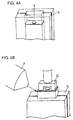
- Fig. 4A is a diagram illustrating alignment of the cell case and a sealing plate using a split-type fixing jig.
- Fig. 4B is a diagram illustrating laser welding using the jig.
- Fig. 5A is a diagram illustrating the relation between deviation of the sealing plate from the cell case and the direction of incidence of laser beam.
- Fig. 1 is a perspective view of a rectangular cell of the present invention.
- Fig. 2 is a plan view of an open end of a rectangular case of the cell.
- Fig. 3A is a plan view illustrating directions of a laser
- FIG. 5B is a diagram illustrating the relation between deviation of the sealing plate from the cell case and laser weldability.
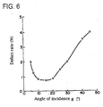
- Fig. 6 is a graph showing the relation between the incident angle of laser beam and failure rate of welding.
- Fig. 7 is a perspective view of another example of a rectangular cell of the present invention.
- Fig. 8 is a partial cross-sectional view illustrating construction of a sealing plate on which fitting portion has been formed.
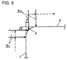
- Fig. 9 is a diagram illustrating difference in focal length of a laser beam at corners.
- Fig. 1 is an external appearance of a rectangular cell in an exemplary embodiment of the present invention.
- a rectangular cell is fabricated by hermetically sealing inside of a rectangular case 1 by welding a sealing plate 2 to an open end of the rectangular case 1 containing a power generating element.
- the rectangular case 1 is formed into a four-sided bottomed cylinder with its open end shaped in a manner such that the longer sides "a” and “b” and the shorter sides “c” and “ d” are straight lines and each of the corners "e” is curved with a predetermined radius as illustrated in Fig. 2.
- the open end of the rectangular case 1 can be hermetically sealed by laying the sealing plate 2 on top of the open end of the rectangular case 1 and laser welding the line of contact formed by connecting the straight lines "a" to "d" of each side with curved corners "e".
- a description will be given on the method for welding the open end of the rectangular case 1 and the sealing plate 2.
- Fig. 3A is a top view of the rectangular case 1 placed at a predetermined position with its open end facing vertically upward and with the sealing plate 2 laid to cover the open end.
- laser beams 3a to 3d are applied to the line of contact 4 between the rectangular case 1 and the sealing plate 2, and each of the laser beams 3a to 3d is scanned respectively in parallel to the longer sides "a" and "b" and shorter sides “c” and “d” to weld the line of contact 4 thereby hermetically sealing the open end of the rectangular case 1 with the sealing plate 2.
- the direction of scanning by each of the laser beams 3a to 3d is a straight line along each of the sides "a" to “d” as described above, control of the movement is easy, enabling precise welding operation.
- the direction of application of the laser beam 3 to scan the line of contact 4 is a slantingly downward direction with an angle ⁇ from the line of contact 4 which is in the horizontal direction.
- FIG. 4A and Fig. 4B are schematic illustrations of the methods to be employed in actual mass production line of rectangular cells for relative positioning of the sealing plate and the case and for securing the cell for laser welding.
- Fig. 4A and Fig. 4B are schematic illustrations of the methods to be employed in actual mass production line of rectangular cells for relative positioning of the sealing plate and the case and for securing the cell for laser welding.
- Prior to laser welding the line of contact 4 of the sealing plate and the case, it is necessary to precisely put one on top of the other along the line of contact. While various methods of alignment are available, simple and fast one is preferable from the standpoint of mass production.
- a split-type fixing jig as illustrated in Fig. 4A enables definition of the position to which a laser beam is to be applied with ease and at a high speed by simultaneously inserting a case and a sealing plate into the jig and fastening the jig. Subsequently, the case and the sealing plate are pressed vertically and secured. This is for the purpose of preventing welding failure due to any gap remaining in the line of contact.
- the entire cell is sledded in the direction of the arrow in Fig. 4A to expose the line of contact out of the jig to allow laser welding.
- Fig. 4B is an illustration of the above described situation.
- Numeral 5 is the split-type fixing jig and numeral 6 is a jig for pressing the sealing plate.
- this mechanical arrangement as it is not good to make the focal length extremely long, it is difficult to position a bulky laser radiating head just beside the arrangement.
- opposing two sides for example shorter sides “c” and “d” including respective corners “e”
- opposing two sides for example shorter sides “c” and “d” including respective corners “e”
- simultaneously welding remaining two sides and respective corners may be simultaneously welded, followed by simultaneously welding remaining two sides and respective corners.
- sequential welding may be performed starting from an arbitrary side including a corner "e”.
- a split jig illustrated in Fig. 4A is employed, which is fastened to ensure positioning of each component.
- the sealing plate is inevitably either slanted or deformed inside the split jig as it can not keep horizontal position. Furthermore, when exposing the surface to be welded to above the split jig by sliding the case upward based on the sides of the case, inconvenience may be experienced such as the sealing plate being cut or deformed because the case may not be smoothly sledded.
- the outer dimensions of the sealing plate and the case be the same, there is a possibility in view of the precision of processing of the metal used that the seal plate be made larger though the designed dimensions are the same. Consequently, taking precision of processing into account, it is advantageous to design the outer dimension of the sealing plate to be no greater than the case even when largest possible sealing plate is made.
- laser welding is a method for fusing the portions irradiated with a laser beam and joining the surfaces in contact with each other, it is extremely susceptible to welding failure such as a hole being made when there is a gap in the portions to be welded. Also, there may have been caused displacement of the surfaces to be joined due to improper way of securing them. In such a case, depending on the incident angle of the laser beam, the laser beam may be partially obstructed by a projected portion of the sealing plate due to displacement and the applied laser power output partially weakened thus being unable to provide required degree of fusion and resulting in inability to secure required welding strength.
- Fig. 5 shows the results obtained.
- the X-axis represents the displacement between the case 1 and the sealing plate 2
- the Y-axis represents the size of the gap.
- a laser beam was applied from the direction as illustrated in Fig. 5A (slanted 15 degrees downward from the horizontal).
- the part on the right of the graph (positive values of X) represents the case where the sealing plate is recessed from the outer end of the case, while the part on the left (negative values of X) represents the case where the sealing plate is projecting from the case.
- Upper part of the graph (large values of Y) represents the direction of increasing gap.
- the percentage figures along the axes represent displacement (X) and gap (Y) of the sealing plate relative to the thickness of the sealing plate. Based on welding tests performed on intentionally prepared samples with various values of displacement and gap, the hatched region of the graph is found to be the region in which welding can be securely performed.
- Fig. 6 shows the change of failure rate of laser welding as a function of the incident angle.
- the rectangular cell shown in Fig. 7 is so constructed that a rectangular case 1 is hermetically sealed by laser welding a sealing plate 8 on which a fitting portion for fitting in the open end of the rectangular case 1 has been formed to the open end to be sealed.
- a fitting portion (recessed portion) 8a that fits in the open end of the rectangular case 1 is provided as illustrated in the partial cross-sectional view in Fig. 8.
- the position of the focal point of the laser beam 3 becomes far at each of the curved corners "e” thus making the welding ability of the laser beam lowered.
- the scan starting position is on the curve of the corner "e", where a maximum focal length difference of ⁇ exists with respect to the position of scanning the longer side "a”.
- the scan ending position Taking the laser beam 3c as an example, it has a maximum focal length difference of ⁇ with respect to the position of scanning the shorter side "c".
- the decrease of welding strength at the corners "e” due to the difference ⁇ in distance can be remedied by the following welding methods.
- One of the methods is to change the laser output at the position where the laser beams 3a to 3d scan respective corners "e" in correspondence to the difference in distance from each of the sides "a” to "d".
- a uniform welding can be performed over the entire line of contact 4.
- a second method is to change the interval of radiating laser pulses in accordance with the difference in distance from each of the sides "a" to “d” at the position where respective laser beams 3a to 3d scan a corner "e".
- the laser pulse radiating interval is shortened, and in the direction in which the difference in distance decreases, the laser pulse radiating interval is made longer.
- the difference in distance can be compensated by the amount of irradiation per unit time by the laser beam 3 by changing the laser pulse radiating interval, uniform welding can be performed over the entire line of contact 4.
- the problem of a separator being directly exposed to the laser beam passing a gap on the surfaces to be joined and is burnt can be solved.
- the sealing plate come in contact with the upper open end of the rectangular case by fitting a recessed portion formed on the sealing plate into the upper open end of the rectangular case, inside of the line of contact on which the rectangular case and the sealing plate come in contact on the outer peripheral can be closed by the recessed portion thereby preventing sputters produced while welding by scanning the line of contact with a laser beam from the side of the rectangular case from entering inside the cell. Also, in the event the amount of fusion due to laser welding exceeds the thickness of the sheet material of the rectangular case, entering of molten metal into the cell can be prevented as the fusion beyond the sheet material thickness reaches the recessed portion.
Landscapes
- Chemical & Material Sciences (AREA)
- Chemical Kinetics & Catalysis (AREA)
- Electrochemistry (AREA)
- General Chemical & Material Sciences (AREA)
- Sealing Battery Cases Or Jackets (AREA)
- Laser Beam Processing (AREA)
- Secondary Cells (AREA)
Abstract
A method for manufacturing a rectangular cell is provided
in which a rectangular case containing a power generating
element is hermetically sealed by laser welding a sealing plate
to an open end of the rectangular case. A sealing plate 2 formed
into the same shape as the upper open end of a rectangular case
1 is laid on the upper open end, laser beams 3a to 3d are applied
in a downward direction from the horizontal to a line of contact
4 comprising sides "a" to "d" including respective corners "e",
and the line of contact 4 is scanned with laser beams 3a to
3d thereby sealing the open end of the case with the sealing
plate.
Description
The present invention relates to a method for
manufacturing rectangular cells, in particular to a method for
manufacturing rectangular cells in which welding method for
welding a sealing plate to an open end of a rectangular case
containing a power generating element and hermetically sealing
it is improved.
Rechargeable batteries to be used as a power supply for
portable electronic devices are required to have a high energy
density as well as a shape with good space-use efficiency to
realize lighter weight and smaller size. As a type of batteries
to satisfy these requirements, lithium-ion rechargeable
batteries using aluminum case are drawing attention. As the
lithium-ion rechargeable batteries are required to keep stable
hermeticity over a long period because of their construction,
an open end of a bottomed rectangular case is sealed by joining
a sealing plate on which to form an electrode by laser welding.
Compared with other welding methods, this laser welding method
has an advantage of having superior working efficiency because
of less thermal influence on the electrolyte contained inside
the case or on electrically insulating parts.
Prior arts of manufacturing a rectangular cell by laser
welding a rectangular case and a sealing plate as disclosed
in Japanese Laid-Open Patent Applications No. Hei 8-315788,
No. Hei 8-315789, and No. Hei 8-315790 are known. In the
manufacturing methods disclosed in these applications, an open
end of a rectangular case is hermetically sealed with a sealing
plate by fitting the sealing plate into the open end of the
rectangular case which is placed with its opening facing upward,
and welding them by applying a laser beam in the vertical
direction to the part where the rectangular case and the sealing
plate are in contact and scanning the contact part with the
laser beam.
However, as laser welding is a method for joining surfaces
in contact with each other by fusing the portion irradiated
with a laser beam, when there is a gap in the portion to be
welded, welding defect such as a hole is easy to be caused on
that place. Also, in the event a laser beam passing a gap is
applied to a separator inside a cell which is weak against heat,
though the output power may be weakened due to defocusing, these
methods suffer a problem of causing a short circuit of the cell
when the separator is burnt. There may also be a case where
there is caused a displacement of the surfaces to be joined
due to improper way of securing the surfaces to be joined. In
such a case, depending on the angle of incidence of the laser
beam, the applied laser output power is partially weakened as
the beam is obstructed by displaced sealing plate thus resulting
in insufficient fusion and making it difficult to secure
required welding strength.
Furthermore, when using a rectangular case and a sealing
plate formed with a thin sheet material for the purpose of
achieving lighter weight and thinner design, and the part of
contact of the sealing plate and the rectangular case is welded
by applying a laser beam from the side of the upper open end
of the rectangular case, there is a risk of molten metal entering
into the cell when the amount of fusion has increased. As there
is a limit in the precision of processing of the sheet material
to be processed into a rectangular case and a sealing plate,
even when the amount of fusion is set to an optimum quantity
which will not reach inside the cell, a short-circuit may be
caused when molten metal spatters to inside the cell in the
event fusion reaching inside the cell takes place due to
dispersion of precision of processing of thin sheet material.
The present invention has been contrived in view of the
above described issues of the prior arts. It is an object of
the present invention to enable joining of a rectangular case
and a sealing plate by uniformly welding them without thermally
affecting inside of the cell and furthermore to provide a method
for manufacturing a rectangular cell with which the welding
failure during mass production is reduced and productivity is
dramatically improved.
In order to achieve the above object, the manufacturing
method in accordance with the present invention is, in a method
for manufacturing a rectangular cell in which a power generating
element is contained in a bottomed rectangular cylindrical case
with its upper open end formed into a shape having four straight
sides and curved corners of a predetermined radius, and the
upper open end of the rectangular case is sealed with a sealing
plate by laser welding the sealing plate to the upper open end
of the rectangular case, to make the sealing plate formed into
the shape of the upper open end come in contact with the upper
open end of the rectangular case, irradiate the line of contact
of the rectangular case and the sealing plate with a laser beam
from the side of the rectangular case in a slantingly downward
direction, and weld the rectangular case and the sealing plate
together by scanning the line of contact with the laser beam.
In doing this, it is preferable that the outer dimension of
at least either of the longer sides or the shorter sides of
the sealing plate is made shorter than the outer dimension of
the upper open end of the bottomed rectangular cylindrical case.
It is also preferable to form the sealing plate into the
shape of the upper open end of the bottomed rectangular
cylindrical case as well as to form a recessed portion which
will fit into the upper open end of the rectangular case, make
the rectangular case and the sealing plate come in contact with
each other with the recessed portion fitted into the upper open
end of the rectangular case, and apply a laser beam to the line
of contact of the rectangular case and the periphery of the
sealing plate from the side of the rectangular case in a
slantingly downward direction. The angle of incidence of the
laser beam is preferably in the range 5 to 45 degrees from the
normal to the side of the case.
With this manufacturing method, as a laser beam is applied
sideways of the cell case, the problem that the beam passing
a gap in the surfaces to be joined directly impinges on and
burns the separator can be solved. By making the outer
dimension of the longer sides and the shorter sides of the
sealing plate shorter than that of the upper open end of the
rectangular case, and applying the laser beam from the side
of the rectangular case in a slantingly downward direction,
it is possible in mass production to precisely put together
the surfaces of the sealing plate and the case to be joined
as well as to remove any part that obstructs the laser beam,
thereby improving the welding reliability.
Furthermore, by making the sealing plate come in contact
with the upper end of the rectangular case by fitting the
recessed portion formed on the sealing plate into the upper
open end of the rectangular case, inside of the line of contact
along which the rectangular case and the sealing plate come
in contact with each other on the outer periphery is closed
by the recessed portion thus preventing sputters from entering
inside the cell when welding by scanning the line of contact
with a laser beam from the side of the rectangular case.
Also, in the event the amount of fusion due to laser welding
exceeds the sheet metal thickness of the rectangular case,
entering inside the cell of molten metal due to fusion can be
prevented as the amount of fusion in excess of the sheet material
thickness reaches the recessed portion.
Fig. 1 is a perspective view of a rectangular cell of the
present invention. Fig. 2 is a plan view of an open end of a
rectangular case of the cell. Fig. 3A is a plan view
illustrating directions of a laser beam scanning along line
of contact on each side. Fig. 3B is a side view illustrating
direction of incidence of the laser beam to the line of contact.
Fig. 4A is a diagram illustrating alignment of the cell case
and a sealing plate using a split-type fixing jig. Fig. 4B is
a diagram illustrating laser welding using the jig. Fig. 5A
is a diagram illustrating the relation between deviation of
the sealing plate from the cell case and the direction of
incidence of laser beam. Fig. 5B is a diagram illustrating the
relation between deviation of the sealing plate from the cell
case and laser weldability. Fig. 6 is a graph showing the
relation between the incident angle of laser beam and failure
rate of welding. Fig. 7 is a perspective view of another example
of a rectangular cell of the present invention. Fig. 8 is a
partial cross-sectional view illustrating construction of a
sealing plate on which fitting portion has been formed. Fig.
9 is a diagram illustrating difference in focal length of a
laser beam at corners.
Referring to the attached drawings, a description of an
exemplary embodiment of the present invention will be given
in the following to aid understanding of the present invention.
Fig. 1 is an external appearance of a rectangular cell
in an exemplary embodiment of the present invention. Here, a
rectangular cell is fabricated by hermetically sealing inside
of a rectangular case 1 by welding a sealing plate 2 to an open
end of the rectangular case 1 containing a power generating
element. The rectangular case 1 is formed into a four-sided
bottomed cylinder with its open end shaped in a manner such
that the longer sides "a" and "b" and the shorter sides "c"
and "d" are straight lines and each of the corners "e" is curved
with a predetermined radius as illustrated in Fig. 2. As the
sealing plate 2 is formed into the same external shape as that
of the open end of the rectangular case 1, the open end of the
rectangular case 1 can be hermetically sealed by laying the
sealing plate 2 on top of the open end of the rectangular case
1 and laser welding the line of contact formed by connecting
the straight lines "a" to "d" of each side with curved corners
"e". In the following, a description will be given on the method
for welding the open end of the rectangular case 1 and the
sealing plate 2.
Fig. 3A is a top view of the rectangular case 1 placed
at a predetermined position with its open end facing vertically
upward and with the sealing plate 2 laid to cover the open end.
As illustrated in Fig. 3B, laser beams 3a to 3d are applied
to the line of contact 4 between the rectangular case 1 and
the sealing plate 2, and each of the laser beams 3a to 3d is
scanned respectively in parallel to the longer sides "a" and
"b" and shorter sides "c" and "d" to weld the line of contact
4 thereby hermetically sealing the open end of the rectangular
case 1 with the sealing plate 2. As the direction of scanning
by each of the laser beams 3a to 3d is a straight line along
each of the sides "a" to "d" as described above, control of
the movement is easy, enabling precise welding operation. Also,
as illustrated in Fig. 3B, the direction of application of the
laser beam 3 to scan the line of contact 4 is a slantingly
downward direction with an angle α from the line of contact
4 which is in the horizontal direction.
Next, advantages of irradiating the line of contact 4 with
each of the laser beams 3a to 3d in a downward direction with
an incident angle α from the horizontal will be described. Fig.
4A and Fig. 4B are schematic illustrations of the methods to
be employed in actual mass production line of rectangular cells
for relative positioning of the sealing plate and the case and
for securing the cell for laser welding. Prior to laser welding
the line of contact 4 of the sealing plate and the case, it
is necessary to precisely put one on top of the other along
the line of contact. While various methods of alignment are
available, simple and fast one is preferable from the standpoint
of mass production.
The use of a split-type fixing jig as illustrated in Fig.
4A enables definition of the position to which a laser beam
is to be applied with ease and at a high speed by simultaneously
inserting a case and a sealing plate into the jig and fastening
the jig. Subsequently, the case and the sealing plate are
pressed vertically and secured. This is for the purpose of
preventing welding failure due to any gap remaining in the line
of contact.
After these operations, the entire cell is sledded in the
direction of the arrow in Fig. 4A to expose the line of contact
out of the jig to allow laser welding. In doing this, in order
to secure the entire body, it is preferable to keep lower part
of the case within the jig rather than to take the entire cell
out of the jig.
Fig. 4B is an illustration of the above described situation.
Numeral 5 is the split-type fixing jig and numeral 6 is a jig
for pressing the sealing plate. In this mechanical arrangement,
as it is not good to make the focal length extremely long, it
is difficult to position a bulky laser radiating head just
beside the arrangement. In view of the mechanical layout space,
it is advantageous to adopt an arrangement illustrated in Fig.
4B.
Especially when aluminum is used as the material for the
case and the sealing plate, a higher laser output is required.
As the laser head becomes larger with increasing laser output,
the welding machine can be positioned only in the way
illustrated in Fig. 4B. Mostly for the above reasons, it is
possible to increase productivity of cell manufacturing while
reducing welding failure by applying each of the laser beams
3a to 3d to the line of contact 4 in a downward direction at
an incident angle α from the horizontal.
By operating four laser beams 3a to 3d along straight lines
respectively in parallel to the longer sides "a" and "b" , and
shorter sides "c" and "d", laser welding of the sides "a", "b"
"c", and "d" including each of the corners "e" can be
simultaneously progressed, thus enabling efficient welding
without suffering any displacement of the sealing plate 2 even
without temporarily fixing the sealing plate 2 laid on the
rectangular case 1.
Furthermore, opposing two sides, for example shorter sides
"c" and "d" including respective corners "e", may be
simultaneously welded, followed by simultaneously welding
remaining two sides and respective corners. In addition, by
temporarily fixing the sealing plate 2 on the rectangular case
1 to keep their relative positions unchanged, sequential
welding may be performed starting from an arbitrary side
including a corner "e".
Next, a description of the advantages of making outer
dimension of at least either of the longer sides or the shorter
sides of the sealing plate shorter than the outer dimension
of the upper open end of the rectangular case will be given.
There are two advantages: one being advantage in defining the
line of contact using a split jig as illustrated in Fig. 4A,
and the other being a dramatic increase in welding reliability
by making the laser incident angle downward by an angle α.
The first advantage will be described first. For the
purpose of precisely aligning the surfaces to be joined of the
sealing plate and the case, a split jig illustrated in Fig.
4A is employed, which is fastened to ensure positioning of each
component.
In doing this, if the outer dimension of the sealing plate
is greater than the outer dimension of the case, when the split
jig is fastened to the sides of the case, the sealing plate
is inevitably either slanted or deformed inside the split jig
as it can not keep horizontal position. Furthermore, when
exposing the surface to be welded to above the split jig by
sliding the case upward based on the sides of the case,
inconvenience may be experienced such as the sealing plate being
cut or deformed because the case may not be smoothly sledded.
While it is normally preferable that the outer dimensions
of the sealing plate and the case be the same, there is a
possibility in view of the precision of processing of the metal
used that the seal plate be made larger though the designed
dimensions are the same. Consequently, taking precision of
processing into account, it is advantageous to design the outer
dimension of the sealing plate to be no greater than the case
even when largest possible sealing plate is made.
Next, the second advantage will be described. As laser
welding is a method for fusing the portions irradiated with
a laser beam and joining the surfaces in contact with each other,
it is extremely susceptible to welding failure such as a hole
being made when there is a gap in the portions to be welded.
Also, there may have been caused displacement of the surfaces
to be joined due to improper way of securing them. In such a
case, depending on the incident angle of the laser beam, the
laser beam may be partially obstructed by a projected portion
of the sealing plate due to displacement and the applied laser
power output partially weakened thus being unable to provide
required degree of fusion and resulting in inability to secure
required welding strength. In order to confirm this phenomenon,
the relation between the gap and displacement between the
sealing plate and the case, and laser weldability was measured.
Fig. 5 shows the results obtained. In Fig. 5A and Fig. 5B, the
X-axis represents the displacement between the case 1 and the
sealing plate 2, and the Y-axis represents the size of the gap.
A laser beam was applied from the direction as illustrated in
Fig. 5A (slanted 15 degrees downward from the horizontal). In
Fig. 5B, the part on the right of the graph (positive values
of X) represents the case where the sealing plate is recessed
from the outer end of the case, while the part on the left
(negative values of X) represents the case where the sealing
plate is projecting from the case. Upper part of the graph
(large values of Y) represents the direction of increasing gap.
Furthermore, in Fig. 5B, the percentage figures along the
axes represent displacement (X) and gap (Y) of the sealing plate
relative to the thickness of the sealing plate. Based on
welding tests performed on intentionally prepared samples with
various values of displacement and gap, the hatched region of
the graph is found to be the region in which welding can be
securely performed.
It is evident from the graph that the optimum region
suddenly narrows as the value of X goes to negative. This is
considered to have been caused by the line of contact 4 to be
welded being obstructed by the sealing plate projecting from
the case thus the laser beam being partially cut-off.
Consequently, it is advantageous that the outer dimension of
the sealing plate be smaller than the outer dimension of the
case.
Now, regarding the laser beam incident angle, although
the angle was 15 degrees from the horizontal in this exemplary
embodiment, conditions of reliable welding can be found down
to 5 degrees from the horizontal depending on the shape of the
split jig and the method of securing. Conversely, when the
angle exceeds 45 degrees from the horizontal, irradiation tends
to be more from above thus naturally greatly losing original
advantages of irradiating from the side.
As a result, it was found from various experiments that
an incident angle range of 5 to 45 degrees is preferable, and
a range of 7 to 25 degrees is especially preferable (ref. Fig.
6). Fig. 6 shows the change of failure rate of laser welding
as a function of the incident angle.
Next, a description will be given on the advantages of
providing a recessed portion on the sealing plate which fits
in the upper open end of the rectangular case. The rectangular
cell shown in Fig. 7 is so constructed that a rectangular case
1 is hermetically sealed by laser welding a sealing plate 8
on which a fitting portion for fitting in the open end of the
rectangular case 1 has been formed to the open end to be sealed.
On the sealing plate 8, a fitting portion (recessed portion)
8a that fits in the open end of the rectangular case 1 is provided
as illustrated in the partial cross-sectional view in Fig. 8.
When welding the line of contact 4 along which the rectangular
case 1 and the sealing plate 8 come in contact by application
of a laser beam 3 from the side of the rectangular case 1 as
illustrated in the diagram, as the portion inside the line of
contact 4 is closed by the recess 8a, sputters of molten metal
will not spatter into the cell even in the event a gap exists
on the line of contact 4 due to processing error or the amount
of fusion exceeds the thickness of the sheet material of the
rectangular case 1. Laser welding is performed by scanning the
line of contact 4 with laser beams 3a to 3d in parallel to the
straight lines of sides "a" , "b", "c", and "d" illustrated in
Fig. 3A similar to what has been described before. The
direction of application of the laser beam 3 was slanted
downward by 15 degrees from the horizontal as illustrated in
Fig. 8.
In the above described exemplary embodiment, when scanning
the laser beam 3 in parallel to each of the sides "a", "b",
"c", and "d", the position of the focal point of the laser beam
3 becomes far at each of the curved corners "e" thus making
the welding ability of the laser beam lowered. In other words,
taking the laser beam 3a in Fig. 9 as an example, the scan
starting position is on the curve of the corner "e", where a
maximum focal length difference of β exists with respect to
the position of scanning the longer side "a". Same situation
applies to the scan ending position. Taking the laser beam 3c
as an example, it has a maximum focal length difference of β
with respect to the position of scanning the shorter side "c".
The decrease of welding strength at the corners "e" due to the
difference β in distance can be remedied by the following
welding methods. One of the methods is to change the laser
output at the position where the laser beams 3a to 3d scan
respective corners "e" in correspondence to the difference in
distance from each of the sides "a" to "d". In other words,
as the reduction in welding ability at a corner "e" where the
position of the focal point is far can be compensated by an
increase in the laser output, a uniform welding can be performed
over the entire line of contact 4.
A second method is to change the interval of radiating
laser pulses in accordance with the difference in distance from
each of the sides "a" to "d" at the position where respective
laser beams 3a to 3d scan a corner "e". To be more specific,
as the difference in distance increases, the laser pulse
radiating interval is shortened, and in the direction in which
the difference in distance decreases, the laser pulse radiating
interval is made longer. As the difference in distance can be
compensated by the amount of irradiation per unit time by the
laser beam 3 by changing the laser pulse radiating interval,
uniform welding can be performed over the entire line of contact
4.
According to the present invention, as a laser beam is
applied from the side of a rectangular case to a line of contact
on which a sealing plate formed into the same shape as the
outside shape of the upper open end of the rectangular case
is made to come in contact with the upper open end of the
rectangular case, the problem of a separator being directly
exposed to the laser beam passing a gap on the surfaces to be
joined and is burnt can be solved. By making the outer dimension
of the longer sides and the shorter sides of the sealing plate
shorter than the outer dimension of the upper open end of the
rectangular case, and applying a laser beam from the side of
the rectangular case in a slantingly downward direction,
surfaces to be joined of the sealing plate and the case can
be precisely aligned during mass production while being able
to eliminate portions that obstruct the laser beam thus
improving welding reliability. Furthermore, by making the
sealing plate come in contact with the upper open end of the
rectangular case by fitting a recessed portion formed on the
sealing plate into the upper open end of the rectangular case,
inside of the line of contact on which the rectangular case
and the sealing plate come in contact on the outer peripheral
can be closed by the recessed portion thereby preventing
sputters produced while welding by scanning the line of contact
with a laser beam from the side of the rectangular case from
entering inside the cell. Also, in the event the amount of
fusion due to laser welding exceeds the thickness of the sheet
material of the rectangular case, entering of molten metal into
the cell can be prevented as the fusion beyond the sheet material
thickness reaches the recessed portion.
- 1:
- Rectangular case
- 2, 8:
- Sealing plate
- 3,3a, 3b, 3c, 3d:
- Laser beam
- 4:
- Line of contact
- 5:
- Split-type fixing jig
- 6:
- Sealing plate pressing jig
- 7:
- Laser radiation head
- 8a:
- Fitting portion
- "a", "b", "c", "d":
- Straight side
- "e":
- Corner
Claims (4)
- A method for manufacturing a rectangular cell by housing a power generating element inside a bottomed rectangular cylinder with its upper open end formed into an opening having four sides of a rectangle consisting of straight lines and curved corners with a predetermined radius, and sealing the upper open end of the rectangular case with a sealing plate by laser welding the sealing plate to the upper open end of the rectangular case, wherein the sealing plate formed into the shape of the upper open end is made to come in contact with the upper open end of the rectangular case, a laser beam is applied to the line of contact of the rectangular case and the sealing plate from the side of the rectangular case in a slantingly downward direction, and the laser beam scans the line of contact thereby to weld the rectangular case and the sealing plate.
- The method for manufacturing a rectangular cell of claim 1, wherein the outer dimension of at least either of the longer sides or the shorter sides of the sealing plate is made shorter than the outer dimension of the upper open end of the bottomed rectangular cylindrical case.
- The method for manufacturing a rectangular cell of claim 1, wherein the sealing plate is formed into the shape of an upper open end of a bottomed rectangular cylindrical case while a recessed portion to fit into the upper open end of the rectangular case is formed on said sealing plate, the rectangular case and the sealing plate are made to come in contact in a state in which said recessed portion is fitted in the upper open end of the rectangular case, and a laser beam is applied to the line of contact of the rectangular case and the periphery of the sealing plate from the side of the rectangular case in a slantingly downward direction.
- The method for manufacturing a rectangular cell of claim 1, wherein the laser beam to be applied from the side of the rectangular case in a slantingly downward direction has an incident angle in a range 5 to 45 degrees from the normal to the side of the case.
Applications Claiming Priority (3)
| Application Number | Priority Date | Filing Date | Title |
|---|---|---|---|
| JP10304862A JP2000133211A (en) | 1998-10-27 | 1998-10-27 | Manufacturing method for prismatic batteries |
| JP30486298 | 1998-10-27 | ||
| PCT/JP1999/005868 WO2000025374A1 (en) | 1998-10-27 | 1999-10-25 | Method for producing square cell |
Publications (2)
| Publication Number | Publication Date |
|---|---|
| EP1043784A1 true EP1043784A1 (en) | 2000-10-11 |
| EP1043784A4 EP1043784A4 (en) | 2003-06-04 |
Family
ID=17938180
Family Applications (1)
| Application Number | Title | Priority Date | Filing Date |
|---|---|---|---|
| EP99949389A Withdrawn EP1043784A4 (en) | 1998-10-27 | 1999-10-25 | PROCESS FOR PRODUCING A RECTANGULAR CELL |
Country Status (6)
| Country | Link |
|---|---|
| US (1) | US6627348B1 (en) |
| EP (1) | EP1043784A4 (en) |
| JP (1) | JP2000133211A (en) |
| KR (1) | KR20010033636A (en) |
| CN (1) | CN1151565C (en) |
| WO (1) | WO2000025374A1 (en) |
Cited By (3)
| Publication number | Priority date | Publication date | Assignee | Title |
|---|---|---|---|---|
| WO2008038086A1 (en) * | 2006-09-26 | 2008-04-03 | Toyota Jidosha Kabushiki Kaisha | Battery and method for manufacturing battery |
| EP2172993A4 (en) * | 2007-07-23 | 2014-01-15 | Toyota Motor Co Ltd | BATTERY HOUSING AND BATTERY HAVING A PLATE OF SEALING |
| EP2830121A1 (en) * | 2013-07-26 | 2015-01-28 | Samsung SDI Co., Ltd. | Rechargeable battery |
Families Citing this family (15)
| Publication number | Priority date | Publication date | Assignee | Title |
|---|---|---|---|---|
| JP5465841B2 (en) * | 2008-05-16 | 2014-04-09 | 日立マクセル株式会社 | Manufacturing method and manufacturing apparatus for sealed battery |
| JP5229594B2 (en) * | 2008-12-16 | 2013-07-03 | トヨタ自動車株式会社 | Sealed battery |
| JP5727757B2 (en) * | 2009-12-25 | 2015-06-03 | 芝浦メカトロニクス株式会社 | Sealing can device |
| JP5504007B2 (en) * | 2010-02-26 | 2014-05-28 | 日立ビークルエナジー株式会社 | Square battery and method for manufacturing the same |
| JP5997929B2 (en) * | 2012-05-09 | 2016-09-28 | 福伸電機株式会社 | Method for manufacturing exterior body for power storage element |
| CN106887536B (en) * | 2012-08-31 | 2020-01-10 | 日立汽车系统株式会社 | Square secondary battery |
| JP5971117B2 (en) * | 2012-12-27 | 2016-08-17 | 株式会社豊田自動織機 | Secondary battery welding jig |
| CN104078631B (en) | 2013-03-27 | 2019-03-08 | 株式会社杰士汤浅国际 | Charge storage element and electrical storage device |
| JP6084905B2 (en) * | 2013-07-02 | 2017-02-22 | 日立オートモティブシステムズ株式会社 | Battery and battery manufacturing method |
| JP2015092456A (en) * | 2013-10-01 | 2015-05-14 | 住友電気工業株式会社 | Sealed power storage device and manufacturing method thereof |
| US11020820B2 (en) | 2014-04-15 | 2021-06-01 | Panasonic Intellectual Property Management Co., Ltd. | Laser welding method |
| JP6428542B2 (en) | 2015-09-16 | 2018-11-28 | トヨタ自動車株式会社 | Manufacturing method of sealed battery |
| WO2021187349A1 (en) * | 2020-03-19 | 2021-09-23 | 三洋電機株式会社 | Sealed battery |
| US12597660B2 (en) | 2020-04-10 | 2026-04-07 | Lg Energy Solution, Ltd. | Battery module and method of manufacturing the same |
| JP7749612B2 (en) * | 2023-02-22 | 2025-10-06 | プライムプラネットエナジー&ソリューションズ株式会社 | Method for manufacturing an electricity storage device |
Family Cites Families (14)
| Publication number | Priority date | Publication date | Assignee | Title |
|---|---|---|---|---|
| JPS57145265A (en) * | 1981-03-02 | 1982-09-08 | Sanyo Electric Co Ltd | Battery sealing method |
| JPS5810364A (en) * | 1981-07-13 | 1983-01-20 | Sanyo Electric Co Ltd | Sealing of battery |
| EP0969536A3 (en) * | 1994-03-03 | 2003-10-08 | Japan Storage Battery Company Limited | Battery |
| JPH08315790A (en) | 1995-03-13 | 1996-11-29 | Nippondenso Co Ltd | Welding method for closed container of prismatic battery |
| JPH08315789A (en) | 1995-03-14 | 1996-11-29 | Nippondenso Co Ltd | Method of manufacturing prismatic battery |
| JPH08315788A (en) | 1995-03-15 | 1996-11-29 | Nippondenso Co Ltd | Method of manufacturing prismatic battery |
| JP3175558B2 (en) * | 1995-10-24 | 2001-06-11 | 松下電器産業株式会社 | Sealed storage battery |
| JPH09259841A (en) | 1996-03-25 | 1997-10-03 | Shin Kobe Electric Mach Co Ltd | Sealed battery |
| JPH10144268A (en) * | 1996-11-08 | 1998-05-29 | Mitsubishi Cable Ind Ltd | Sealed structure of sealed battery |
| JP3455044B2 (en) * | 1997-01-20 | 2003-10-06 | 株式会社東芝 | Laser welding method, secondary battery manufacturing method, and laser welding apparatus |
| US6001504A (en) * | 1998-03-11 | 1999-12-14 | Duracell Inc. | Prismatic battery housing |
| JPH11307065A (en) * | 1998-04-24 | 1999-11-05 | Mitsubishi Cable Ind Ltd | Manufacture of sealed battery |
| US6204635B1 (en) * | 1998-05-22 | 2001-03-20 | Texas Instruments Incorporated | Current interrupt apparatus particularly adapted for use with prismatic electrochemical cells |
| US6268079B1 (en) * | 1998-11-25 | 2001-07-31 | Japan Storage Battery Co., Ltd. | Nonaqueous-electrolyte battery |
-
1998
- 1998-10-27 JP JP10304862A patent/JP2000133211A/en active Pending
-
1999
- 1999-10-25 KR KR1020007007154A patent/KR20010033636A/en not_active Ceased
- 1999-10-25 EP EP99949389A patent/EP1043784A4/en not_active Withdrawn
- 1999-10-25 US US09/582,387 patent/US6627348B1/en not_active Expired - Fee Related
- 1999-10-25 WO PCT/JP1999/005868 patent/WO2000025374A1/en not_active Ceased
- 1999-10-25 CN CNB998018945A patent/CN1151565C/en not_active Expired - Fee Related
Cited By (6)
| Publication number | Priority date | Publication date | Assignee | Title |
|---|---|---|---|---|
| WO2008038086A1 (en) * | 2006-09-26 | 2008-04-03 | Toyota Jidosha Kabushiki Kaisha | Battery and method for manufacturing battery |
| US8293400B2 (en) | 2006-09-26 | 2012-10-23 | Toyota Jidosha Kabushiki Kaisha | Battery including opening closure member with case contact part and case inside part |
| US8308826B2 (en) | 2006-09-26 | 2012-11-13 | Toyota Jidosha Kabushiki Kaisha | Battery and method for manufacturing battery |
| EP2172993A4 (en) * | 2007-07-23 | 2014-01-15 | Toyota Motor Co Ltd | BATTERY HOUSING AND BATTERY HAVING A PLATE OF SEALING |
| EP2830121A1 (en) * | 2013-07-26 | 2015-01-28 | Samsung SDI Co., Ltd. | Rechargeable battery |
| US9608240B2 (en) | 2013-07-26 | 2017-03-28 | Samsung Sdi Co., Ltd. | Rechargeable battery |
Also Published As
| Publication number | Publication date |
|---|---|
| WO2000025374A1 (en) | 2000-05-04 |
| CN1287692A (en) | 2001-03-14 |
| US6627348B1 (en) | 2003-09-30 |
| HK1034363A1 (en) | 2001-10-19 |
| KR20010033636A (en) | 2001-04-25 |
| CN1151565C (en) | 2004-05-26 |
| JP2000133211A (en) | 2000-05-12 |
| EP1043784A4 (en) | 2003-06-04 |
Similar Documents
| Publication | Publication Date | Title |
|---|---|---|
| US6627348B1 (en) | Method for producing rectangular cell | |
| KR100471169B1 (en) | Method of manufacturing a rectangular battery | |
| JP6910965B2 (en) | Electric connection method of power supply device, vehicle using it, bus bar, and battery cell using this bus bar | |
| KR102143052B1 (en) | Device case and method of manufacturing the same | |
| US20060207085A1 (en) | Battery and method for manufacturing same | |
| JP6085058B1 (en) | Battery can and battery | |
| US11338389B2 (en) | Battery case sealing method and a sealed battery manufacturing method | |
| CN117638336A (en) | Battery casing and power battery | |
| US5279623A (en) | Method of fabricating flat type electrochemical device | |
| KR101838382B1 (en) | Sealed battery and a method for manufacturing the same | |
| JP6341054B2 (en) | Storage element manufacturing method and storage element | |
| JP2010097770A (en) | Battery casing, secondary battery and method for manufacturing secondary battery | |
| JP4743985B2 (en) | Battery manufacturing method | |
| CN117996302A (en) | Secondary battery | |
| JP3608994B2 (en) | Sealed battery | |
| JPH08315788A (en) | Method of manufacturing prismatic battery | |
| CN115708252B (en) | Battery pack and manufacturing method thereof | |
| JP2001093506A (en) | Electrode joining method for storage element | |
| JPH11167904A (en) | Method for manufacturing prismatic battery | |
| WO1999017386A1 (en) | Method of manufacturing a rectangular battery | |
| JP4074012B2 (en) | Method for manufacturing prismatic battery | |
| JP2009087707A (en) | Cell terminal structure, cell terminal connection structure, and cell terminal manufacturing method. | |
| US20260027654A1 (en) | Welding method and welding structure | |
| JP2001093504A (en) | Battery and manufacturing method thereof | |
| KR20180079837A (en) | Welding Method Capable of Improving Welding-Reliability through Accurate Definition about Welding Portion of Electrode Tabs |
Legal Events
| Date | Code | Title | Description |
|---|---|---|---|
| PUAI | Public reference made under article 153(3) epc to a published international application that has entered the european phase |
Free format text: ORIGINAL CODE: 0009012 |
|
| 17P | Request for examination filed |
Effective date: 20000717 |
|
| AK | Designated contracting states |
Kind code of ref document: A1 Designated state(s): AT BE CH CY DE DK ES FI FR GB GR IE IT LI LU MC NL PT SE |
|
| A4 | Supplementary search report drawn up and despatched |
Effective date: 20030424 |
|
| STAA | Information on the status of an ep patent application or granted ep patent |
Free format text: STATUS: THE APPLICATION HAS BEEN WITHDRAWN |
|
| 18W | Application withdrawn |
Effective date: 20030801 |
|
| RBV | Designated contracting states (corrected) |
Designated state(s): DE FR GB |