EP1043508A2 - A ball joint for cable guide - Google Patents
A ball joint for cable guide Download PDFInfo
- Publication number
- EP1043508A2 EP1043508A2 EP99118341A EP99118341A EP1043508A2 EP 1043508 A2 EP1043508 A2 EP 1043508A2 EP 99118341 A EP99118341 A EP 99118341A EP 99118341 A EP99118341 A EP 99118341A EP 1043508 A2 EP1043508 A2 EP 1043508A2
- Authority
- EP
- European Patent Office
- Prior art keywords
- cable
- guide member
- hollow shaft
- cubic body
- ball joint
- Prior art date
- Legal status (The legal status is an assumption and is not a legal conclusion. Google has not performed a legal analysis and makes no representation as to the accuracy of the status listed.)
- Granted
Links
Images

Classifications
-
- F—MECHANICAL ENGINEERING; LIGHTING; HEATING; WEAPONS; BLASTING
- F16—ENGINEERING ELEMENTS AND UNITS; GENERAL MEASURES FOR PRODUCING AND MAINTAINING EFFECTIVE FUNCTIONING OF MACHINES OR INSTALLATIONS; THERMAL INSULATION IN GENERAL
- F16C—SHAFTS; FLEXIBLE SHAFTS; ELEMENTS OR CRANKSHAFT MECHANISMS; ROTARY BODIES OTHER THAN GEARING ELEMENTS; BEARINGS
- F16C1/00—Flexible shafts; Mechanical means for transmitting movement in a flexible sheathing
- F16C1/26—Construction of guiding-sheathings or guiding-tubes
- F16C1/262—End fittings; Attachment thereof to the sheathing or tube
- F16C1/265—End fittings; Attachment thereof to the sheathing or tube with a swivel tube connected to the end-fitting of a sheathing, e.g. with a spherical joint
-
- Y—GENERAL TAGGING OF NEW TECHNOLOGICAL DEVELOPMENTS; GENERAL TAGGING OF CROSS-SECTIONAL TECHNOLOGIES SPANNING OVER SEVERAL SECTIONS OF THE IPC; TECHNICAL SUBJECTS COVERED BY FORMER USPC CROSS-REFERENCE ART COLLECTIONS [XRACs] AND DIGESTS
- Y10—TECHNICAL SUBJECTS COVERED BY FORMER USPC
- Y10T—TECHNICAL SUBJECTS COVERED BY FORMER US CLASSIFICATION
- Y10T403/00—Joints and connections
- Y10T403/32—Articulated members
- Y10T403/32606—Pivoted
- Y10T403/32631—Universal ball and socket
- Y10T403/32672—Swiveled ball parts or seat
-
- Y—GENERAL TAGGING OF NEW TECHNOLOGICAL DEVELOPMENTS; GENERAL TAGGING OF CROSS-SECTIONAL TECHNOLOGIES SPANNING OVER SEVERAL SECTIONS OF THE IPC; TECHNICAL SUBJECTS COVERED BY FORMER USPC CROSS-REFERENCE ART COLLECTIONS [XRACs] AND DIGESTS
- Y10—TECHNICAL SUBJECTS COVERED BY FORMER USPC
- Y10T—TECHNICAL SUBJECTS COVERED BY FORMER US CLASSIFICATION
- Y10T74/00—Machine element or mechanism
- Y10T74/20—Control lever and linkage systems
- Y10T74/20396—Hand operated
- Y10T74/20402—Flexible transmitter [e.g., Bowden cable]
- Y10T74/20462—Specific cable connector or guide
Definitions
- the present invention relates to a ball joint for use of various industrial appliances, in particular, for use of a cable guide.
- a ball joint for cable guide is structured as shown in Fig. 4.
- Reference numeral 1 designates a ball joint and 2 designates a cable and the ball joint 1 is interposed between a cable fixation table 3 for fixing one end of the cable and a cable supporting table 4 for supporting an intermediate portion of the cable and changing the drawn out direction approximately at 90 degrees.
- the ball joint 1 comprises a U-letter shaped retainer 5, a shaft 6 bridged between a pair of erected pieces 5a of U-letter shaped retainer, a cubic body 7 coupled rotatably with the shaft 6, an outer ring 8 to be coupled with the cubic surface of the cubic body 7, wherein the retainer 5 is mounted on a mounting plate 9 with a bolt 10 connected to the bottom of the leg portions 3a of the cable fixation table 3 with bolt 9, on the other hand, the outer ring 8 is mounted on one end 4a of the supporting table 4 with bolt 11.
- the cable 2 is drawn downward approximately vertically from the cable fixation table 3, then make wound two or three times in loop on the cable supporting table 4, further drawn out approximately horizontal direction through a ring guide 12 on the cable supporting table 4.
- its cubic body 7 rotates against shaft 6 and the outer ring 8 also rotates against the cubic body 7, so that the cable supporting table 4 can swing three-dimensionally, which guarantees the cable 2 to move free.
- the present invention has been made to solve the above problem and is to provide a ball joint for guiding a cable which guarantees a smooth movement of the cable, thereby contributes greatly to increase the endurance of the cable.
- a ball joint comprises a ball and an outer ring to couple with the cubic surface of the ball, which is supported by a stationary retainer, said ball is pierced with a cable insertion hole which has an widened portion toward opening like a horn as a guide hole, in communication with which a guide member for guiding a cable inserted in this insertion hole is provided adjacently to the ball.
- the ball joint for cable guide thus constructed, by guiding a cable through the ball under the outer ring and inside the guide member which is in communication with the ball, the free movement of the cable is guaranteed because the ball and the guide member follow the movement of the cable in unitary manner, in addition, since the cable is guided along the inside and horn-like face of the guide member, it can be prevented from being bent at a sharp angle or twisted.
- a hollow shaft having screw at its tip end can be inserted in the cable insertion hole of the ball and connected by being screwed in the guide member, thereby those are made in a unit, and the hollow portion of the hollow shaft can be used as a cable guide path.
- the retainer is configured as a bottomed box and it is positioned upside-down, and at the top where the outer ring supporting member is disposed and on the side of the retainer an outlet is provided for taking out the cable drawn out from the guide member.
- a turning angle of the cubic body can be limited.
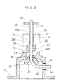
- Fig. 1 is a sectional view showing the structure of the ball joint for cable guide of the present invention.
- Fig. 2 is an exploded and sectional view showing the ball joint.
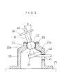
- Fig. 3 is a sectional view of the operational structure of the ball joint.
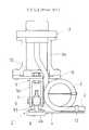
- Fig. 4 is a side view showing the structure and the using manner of the conventional ball joint for cable guide.
- FIGs. 1 - 3 show a ball joint for cable guide as an embodiment of the present invention.
- reference numeral 20 designates a bottomed box shaped retainer. It is positioned on the stand 21 in an upside-down manner and fixed thereon by making use of a flange 22 provided around an opening peripheral of the box with bolts.
- the upside-down bottom 20a of the box is shaped conical, and at the tip of the conical shape a recessed portion (an outer ring supporting portion) 24 for supporting the outer ring 23 to be coupled spherically with the cubic surface of the cubic body 22 is provided.
- the recessed portion 24 is formed as large as enough to accommodate completely the outer ring 23, and the outer ring 23 is, in the state coupled with the recessed portion 24, clamped fixedly between the bottom of the recessed portion 24 and a holding plate 26 mounted on the retainer 20 with bolts 25.
- the cubic body 22 and the outer ring 23 are sub-assembled as becoming unitary, and in the state where the outer ring 23 is coupled with the recessed portion 24, one portion of the cubic body 22 is adapted to be exposed through openings 24a, 26a (Fig. 2) provided in the bottom of the recessed portion 24 and the holding plate 26.
- a pair of flat portions 27, 28 parallel with each other are formed, and through these flat portions 27, 28 and the cubic body 22, a piercing hole (cable insertion hole) 29 is provided (Fig. 2).
- a conically shaped guide member 31 having inside a guide hole 30 which is widened outwardly like a horn and a stepped and hollow shaft 32 are provided in clamping the cubic body 22 in a unitary manner.
- the hollow shaft 32 comprises a large diameter portion 33 which is a little larger than the diameter of the piercing hole 29 and, by connecting thereto, a small diameter portion 34 having a diameter a little smaller than the pierced hole 29, the tip end of that small diameter portion 34 is formed with male screw portion 35.
- a connection portion of the guide member 31 to the cubic body 22 is formed with a female screw portion 36 which is screwed with the male screw portion 35, whereby, in the piercing hole 29 of the cubic body 22, the small diameter portion 34 is inserted and the male portion 35 of the member 31, the guide member 31 is lifted up until it abuts to the lower flat portion 27 of the cubic body 22 and the hollow shaft 32 is descended until the stepped portion 37 between the large diameter portion 33 and the small diameter portion 34 of the hollow shaft 32 touch to the upper flat portion 28 of the cubic body 22, thereby, the guide member 31 and the hollow shaft 32 are rigidly assembled while clamping the cubic body 22 firmly in a unitary manner.
- a sign 38 designates a handle 40 for turning the hollow shaft 32 at the time of assembling.
- hollow shaft 32 has a diameter which is a little larger than the diameter of the cable 40.
- This hollow shaft 32 as described above, is extended to the inner side of the guide member 31 through the piercing hole 29 of the cubic body 22, accordingly, the cable 40 is enabled to be drawn out vertically through the hollow shaft 32, the cubic body 22 and the guide member 31.
- an outlet 41 for taking out the cable 40 is provided, then the cable 40 drawn out downward from the guide member 31 is adapted to be drawn out horizontally making use of this outlet 41 while changing its drawn out direction approximately at 90 degrees.
- a bush 42 as a damper made of such as rubber or plastic is coupled.
- an assembly pre-assembled with the cubic body 22 and the outer ring 23 is coupled with the recessed portion 24 of the top of the retainer 20, subsequently the holding plate 26 is mounted on the top end of the retainer 20 with bolts 25 to fix the assembly in position.
- the small diameter portion 34 of the hollow shaft 32 is inserted in the piercing hole 29 of the cubic body 22, and by screwing the male screw portion 35 of the top end of the small diameter portion 34 in the female portion 36 of the guide member 31, the guide member 31 and the hollow shaft 32 are united while clamping the cubic body 22, and thereby the assembly of the ball joint is finished.
- the cable 40 is inserted in the hollow shaft 32 from the upper, drawn out down the guide member 31, bent along the inner surface (R face) of the guide hole 30 figured like horn and taken out horizontally from the cable outlet 41 of the retainer 20 by changing the drawn out direction at approximately 90 degrees from vertical direction.
- the cable 40 since the cable 40 is supported by the hollow shaft 32 also in the upper side of the cubic body 22, the cable 40 does not get in touch with the holding plate 26 around the cubic body 2 and the outer ring 23, and in addition, since the bush 42 made of a damping material is coupled with the outlet 41, the cable 40 is not hung thereon, and so that the cable 40 does not interfere with the other members to avoid in advance from being damaged.
- the bush 42 of the outlet 41 or cable 40 may be omitted, but in this case, it is to be considered to chamfer the edge (R face) of the outlet 41 for avoiding the cable 40 from being hung thereon.
- the ball joint for cable guide of the present invention it is guaranteed for the cable to move smoothly without setting it in loop, and a damage of the cable or the lead in the cable can be avoided in advance to improve the endurance of the cable outstandingly.
Landscapes
- Engineering & Computer Science (AREA)
- General Engineering & Computer Science (AREA)
- Health & Medical Sciences (AREA)
- Oral & Maxillofacial Surgery (AREA)
- Mechanical Engineering (AREA)
- Pivots And Pivotal Connections (AREA)
- Installation Of Indoor Wiring (AREA)
- Orthopedics, Nursing, And Contraception (AREA)
Abstract
Description
- The present invention relates to a ball joint for use of various industrial appliances, in particular, for use of a cable guide.
- Conventionally, a ball joint for cable guide is structured as shown in Fig. 4.
Reference numeral 1 designates a ball joint and 2 designates a cable and theball joint 1 is interposed between a cable fixation table 3 for fixing one end of the cable and a cable supporting table 4 for supporting an intermediate portion of the cable and changing the drawn out direction approximately at 90 degrees. Theball joint 1 comprises a U-letter shapedretainer 5, ashaft 6 bridged between a pair of erectedpieces 5a of U-letter shaped retainer, acubic body 7 coupled rotatably with theshaft 6, anouter ring 8 to be coupled with the cubic surface of thecubic body 7, wherein theretainer 5 is mounted on a mounting plate 9 with abolt 10 connected to the bottom of theleg portions 3a of the cable fixation table 3 with bolt 9, on the other hand, theouter ring 8 is mounted on oneend 4a of the supporting table 4 withbolt 11. - In operation, the
cable 2 is drawn downward approximately vertically from the cable fixation table 3, then make wound two or three times in loop on the cable supporting table 4, further drawn out approximately horizontal direction through aring guide 12 on the cable supporting table 4. In the above mentionedball joint 1, itscubic body 7 rotates againstshaft 6 and theouter ring 8 also rotates against thecubic body 7, so that the cable supporting table 4 can swing three-dimensionally, which guarantees thecable 2 to move free. - By the way, according to the above mentioned cable guide system, if the
cable 2 is not wound in a loop on the cable supporting table 4, in case the cable supporting table 4 is swung greatly, an excessive tension is put on thecable 2, or thecable 2 is forced to be bent at a sharp angle, so that it has become an unavoidable condition to wind in loop on the cable supporting table 4. - However, there has been a problem in which, when the
cable 2 is wound in loop on the cable supporting table 4, in accordance with the swinging of the cable supporting table 4 thecable 2 is apt to be damaged or due to a friction contact between the cable and the cable supporting table. In addition, due to a three-dimensional swinging of the cable supporting table 4, thecable 2 has been apt to be twisted at the looped portion, so that a lead in the cable is threatened to be broken. - The present invention has been made to solve the above problem and is to provide a ball joint for guiding a cable which guarantees a smooth movement of the cable, thereby contributes greatly to increase the endurance of the cable.
- To attain the above object, in the present invention, a ball joint comprises a ball and an outer ring to couple with the cubic surface of the ball, which is supported by a stationary retainer, said ball is pierced with a cable insertion hole which has an widened portion toward opening like a horn as a guide hole, in communication with which a guide member for guiding a cable inserted in this insertion hole is provided adjacently to the ball.
- In the ball joint for cable guide thus constructed, by guiding a cable through the ball under the outer ring and inside the guide member which is in communication with the ball, the free movement of the cable is guaranteed because the ball and the guide member follow the movement of the cable in unitary manner, in addition, since the cable is guided along the inside and horn-like face of the guide member, it can be prevented from being bent at a sharp angle or twisted.
- In the present invention, a hollow shaft having screw at its tip end can be inserted in the cable insertion hole of the ball and connected by being screwed in the guide member, thereby those are made in a unit, and the hollow portion of the hollow shaft can be used as a cable guide path.
- Also the retainer is configured as a bottomed box and it is positioned upside-down, and at the top where the outer ring supporting member is disposed and on the side of the retainer an outlet is provided for taking out the cable drawn out from the guide member. In this case, by engaging the guide member with the side of the retainer, a turning angle of the cubic body can be limited.
- Fig. 1 is a sectional view showing the structure of the ball joint for cable guide of the present invention.
- Fig. 2 is an exploded and sectional view showing the ball joint.
- Fig. 3 is a sectional view of the operational structure of the ball joint.
- Fig. 4 is a side view showing the structure and the using manner of the conventional ball joint for cable guide.
- Hereinafter, an embodiment of the present invention will be explained based on the attached drawings.
- Figs. 1 - 3, show a ball joint for cable guide as an embodiment of the present invention. In these figures,
reference numeral 20 designates a bottomed box shaped retainer. It is positioned on thestand 21 in an upside-down manner and fixed thereon by making use of aflange 22 provided around an opening peripheral of the box with bolts. The upside-downbottom 20a of the box is shaped conical, and at the tip of the conical shape a recessed portion (an outer ring supporting portion) 24 for supporting theouter ring 23 to be coupled spherically with the cubic surface of thecubic body 22 is provided. Therecessed portion 24 is formed as large as enough to accommodate completely theouter ring 23, and theouter ring 23 is, in the state coupled with therecessed portion 24, clamped fixedly between the bottom of therecessed portion 24 and aholding plate 26 mounted on theretainer 20 withbolts 25. Thecubic body 22 and theouter ring 23 are sub-assembled as becoming unitary, and in the state where theouter ring 23 is coupled with therecessed portion 24, one portion of thecubic body 22 is adapted to be exposed throughopenings recessed portion 24 and theholding plate 26. - On the outer circumference of the
cubic body 22, a pair offlat portions flat portions cubic body 22, a piercing hole (cable insertion hole) 29 is provided (Fig. 2). On the other hand, a conicallyshaped guide member 31 having inside aguide hole 30 which is widened outwardly like a horn and a stepped andhollow shaft 32 are provided in clamping thecubic body 22 in a unitary manner. - In more detail, the
hollow shaft 32 comprises alarge diameter portion 33 which is a little larger than the diameter of thepiercing hole 29 and, by connecting thereto, asmall diameter portion 34 having a diameter a little smaller than the piercedhole 29, the tip end of thatsmall diameter portion 34 is formed withmale screw portion 35. On the other hand, a connection portion of theguide member 31 to thecubic body 22 is formed with afemale screw portion 36 which is screwed with themale screw portion 35, whereby, in thepiercing hole 29 of thecubic body 22, thesmall diameter portion 34 is inserted and themale portion 35 of themember 31, theguide member 31 is lifted up until it abuts to the lowerflat portion 27 of thecubic body 22 and thehollow shaft 32 is descended until thestepped portion 37 between thelarge diameter portion 33 and thesmall diameter portion 34 of thehollow shaft 32 touch to the upperflat portion 28 of thecubic body 22, thereby, theguide member 31 and thehollow shaft 32 are rigidly assembled while clamping thecubic body 22 firmly in a unitary manner. For reference, asign 38 designates ahandle 40 for turning thehollow shaft 32 at the time of assembling. - Now,
hollow shaft 32 has a diameter which is a little larger than the diameter of thecable 40. Thishollow shaft 32, as described above, is extended to the inner side of theguide member 31 through thepiercing hole 29 of thecubic body 22, accordingly, thecable 40 is enabled to be drawn out vertically through thehollow shaft 32, thecubic body 22 and theguide member 31. On the other hand, on one side wall of theretainer 20 anoutlet 41 for taking out thecable 40 is provided, then thecable 40 drawn out downward from theguide member 31 is adapted to be drawn out horizontally making use of thisoutlet 41 while changing its drawn out direction approximately at 90 degrees. For reference, in this outlet 41 abush 42 as a damper made of such as rubber or plastic is coupled. - In assembling the above ball joint, an assembly pre-assembled with the
cubic body 22 and theouter ring 23 is coupled with therecessed portion 24 of the top of theretainer 20, subsequently theholding plate 26 is mounted on the top end of theretainer 20 withbolts 25 to fix the assembly in position. Next, thesmall diameter portion 34 of thehollow shaft 32 is inserted in thepiercing hole 29 of thecubic body 22, and by screwing themale screw portion 35 of the top end of thesmall diameter portion 34 in thefemale portion 36 of theguide member 31, theguide member 31 and thehollow shaft 32 are united while clamping thecubic body 22, and thereby the assembly of the ball joint is finished. Hereinafter, thecable 40 is inserted in thehollow shaft 32 from the upper, drawn out down theguide member 31, bent along the inner surface (R face) of theguide hole 30 figured like horn and taken out horizontally from thecable outlet 41 of theretainer 20 by changing the drawn out direction at approximately 90 degrees from vertical direction. - In the ball joint structured as mentioned above, when an outer force is applied to the
cable 40, thecubic body 22 rotates within theouter ring 23, thereby theguide member 31 and thehollow shaft 32 swing in a unitary manner and free movement of thecable 40 is guaranteed. Then, since thecable 40 is bent along the inner surface of the horn figuredguide hole 30 of theguide member 31, the cable is never bent at an sharp angle or twisted, and thereby a damage of thecable 40 or of the leads inside the cable is in advance prevented. In this embodiment in particular, since thecable 40 is supported by thehollow shaft 32 also in the upper side of thecubic body 22, thecable 40 does not get in touch with theholding plate 26 around thecubic body 2 and theouter ring 23, and in addition, since thebush 42 made of a damping material is coupled with theoutlet 41, thecable 40 is not hung thereon, and so that thecable 40 does not interfere with the other members to avoid in advance from being damaged. For reference, thebush 42 of theoutlet 41 orcable 40 may be omitted, but in this case, it is to be considered to chamfer the edge (R face) of theoutlet 41 for avoiding thecable 40 from being hung thereon. - On the other hand, when a large force is applied to the
cable 40, theguide member 31 and thehollow shaft 32 are apt to swing, in this case however, as shown in Fig. 3, oneportion 31a of theguide member 31 abuts to the inclined inner surface of thebottom 20a of theretainer 20, which prevents thecubic body 22 from an excessive rotation more than a given angle, that means to prevent thehollow shaft 32 from swinging over a given angle . Thereby, there is no risk where thehollow shaft 32 swings more than necessary to abut to theholding plate 26, so that any damage of not only theouter ring 23 but also thehollow shaft 32 itself is in advance prevented from being damaged. - As mentioned above, according to the ball joint for cable guide of the present invention, it is guaranteed for the cable to move smoothly without setting it in loop, and a damage of the cable or the lead in the cable can be avoided in advance to improve the endurance of the cable outstandingly.
Claims (4)
- A ball joint for cable guide comprises a cubic body and an outer ring, wherein the outer ring is supported by a stationary retainer, a cable inserting hole is provided in the cubic body, a guide member, which has a horn like guiding hole being widened toward the tip end and guides the cable through the cable inserting hole along an inner surface of the guiding hole.
- A ball joint for cable guide according to Claim 1, wherein a screw portion of a tip end of the hollow shaft inserted in the cable insertion hole is screwed in the guide member to make the cubic body, the guide member and the hollow shaft unified, and a hollow inside of the hollow shaft is used as a cable guiding path.
- A ball joint for cable guide according to Claim 1 or 2, wherein the retainer is of a bottomed box shape, at a bottom portion of the box positioned upside-down an outer ring supporting portion is disposed and on a side wall of the retainer an outlet for taking out the cable drawn out from the guide member.
- A ball joint for cable guide according to Claim 1 or 2, wherein the guide member engages with an inner side of the retainer to limit a turning angle of the cubic body.
Applications Claiming Priority (2)
| Application Number | Priority Date | Filing Date | Title |
|---|---|---|---|
| JP11101310A JP2000291626A (en) | 1999-04-08 | 1999-04-08 | Ball joint for guiding cable |
| JP10131099 | 1999-04-08 |
Publications (3)
| Publication Number | Publication Date |
|---|---|
| EP1043508A2 true EP1043508A2 (en) | 2000-10-11 |
| EP1043508A3 EP1043508A3 (en) | 2001-06-20 |
| EP1043508B1 EP1043508B1 (en) | 2005-04-13 |
Family
ID=14297249
Family Applications (1)
| Application Number | Title | Priority Date | Filing Date |
|---|---|---|---|
| EP99118341A Expired - Lifetime EP1043508B1 (en) | 1999-04-08 | 1999-09-16 | A ball joint for cable guide |
Country Status (6)
| Country | Link |
|---|---|
| US (1) | US6213674B1 (en) |
| EP (1) | EP1043508B1 (en) |
| JP (1) | JP2000291626A (en) |
| DE (1) | DE69924703T2 (en) |
| ES (1) | ES2237005T3 (en) |
| SG (1) | SG85672A1 (en) |
Cited By (1)
| Publication number | Priority date | Publication date | Assignee | Title |
|---|---|---|---|---|
| EP1209371A1 (en) * | 2000-11-24 | 2002-05-29 | Constructions Brevetées d' Alfortville - CBA | Pivot for a ball ramp actuator |
Families Citing this family (10)
| Publication number | Priority date | Publication date | Assignee | Title |
|---|---|---|---|---|
| JP4261947B2 (en) * | 2003-03-14 | 2009-05-13 | 矢崎総業株式会社 | Harness fixture for sliding door feeding and feeding structure using it |
| US7703270B2 (en) * | 2005-07-15 | 2010-04-27 | Pratt & Whitney Canada Corp. | Cable connection for a gas turbine engine safety fuel shut-off mechanism |
| US7302907B2 (en) * | 2005-07-25 | 2007-12-04 | Correct Craft, Inc. | Mounting system and method for rigidly attaching a water sports towing frame to a vessel |
| JP4442545B2 (en) * | 2005-10-14 | 2010-03-31 | 住友電装株式会社 | Cable support device |
| TW201030250A (en) * | 2009-02-04 | 2010-08-16 | Avermedia Information Inc | Ball joint structure |
| CN103244550B (en) * | 2013-05-27 | 2015-07-08 | 南京万德游乐设备有限公司 | Steel wire rope universal regulating structure |
| JP6488981B2 (en) * | 2015-10-13 | 2019-03-27 | 住友電装株式会社 | Electric wire routing device |
| CN106048882B (en) * | 2016-05-31 | 2018-02-06 | 安徽省安国渔具有限公司 | A kind of fishing net machine guider |
| CN107872034A (en) * | 2017-12-07 | 2018-04-03 | 重庆创软科技有限公司 | It is easy to the equipment for fixing sleep monitor system connectors |
| GB2577518A (en) * | 2018-09-26 | 2020-04-01 | Jdr Cable Systems Ltd | Termination assembly |
Family Cites Families (7)
| Publication number | Priority date | Publication date | Assignee | Title |
|---|---|---|---|---|
| US2140426A (en) * | 1936-10-09 | 1938-12-13 | Walter D Hodson | Lubricating wire rope |
| US3215405A (en) * | 1962-11-06 | 1965-11-02 | Breeze Corp | Fleet angle control device |
| IT217051Z2 (en) * | 1989-05-12 | 1991-10-29 | Iveco Fiat | FLEXIBLE CABLE PROVIDED WITH PERFEZIO-TYPE EXTREME CONNECTORS |
| FR2678030B1 (en) * | 1991-06-19 | 1994-10-21 | Peugeot | DEVICE FOR FIXING A FLEXIBLE SHEATH IN A WALL. |
| JP3133915B2 (en) * | 1994-11-18 | 2001-02-13 | 株式会社シマノ | Bicycle cable and its outer end cap and adjustment bolt |
| US5570611A (en) * | 1995-07-12 | 1996-11-05 | Teleflex, Inc. | Core terminal for motion-transmitting remote control assembly |
| US5911790A (en) * | 1997-12-05 | 1999-06-15 | Teleflex Corporation | Replaceable snap-in end fitting for a cable control |
-
1999
- 1999-04-08 JP JP11101310A patent/JP2000291626A/en active Pending
- 1999-08-16 US US09/375,155 patent/US6213674B1/en not_active Expired - Fee Related
- 1999-09-01 SG SG9904237A patent/SG85672A1/en unknown
- 1999-09-16 ES ES99118341T patent/ES2237005T3/en not_active Expired - Lifetime
- 1999-09-16 DE DE69924703T patent/DE69924703T2/en not_active Expired - Fee Related
- 1999-09-16 EP EP99118341A patent/EP1043508B1/en not_active Expired - Lifetime
Non-Patent Citations (1)
| Title |
|---|
| None |
Cited By (1)
| Publication number | Priority date | Publication date | Assignee | Title |
|---|---|---|---|---|
| EP1209371A1 (en) * | 2000-11-24 | 2002-05-29 | Constructions Brevetées d' Alfortville - CBA | Pivot for a ball ramp actuator |
Also Published As
| Publication number | Publication date |
|---|---|
| SG85672A1 (en) | 2002-01-15 |
| DE69924703D1 (en) | 2005-05-19 |
| JP2000291626A (en) | 2000-10-20 |
| DE69924703T2 (en) | 2006-03-09 |
| ES2237005T3 (en) | 2005-07-16 |
| EP1043508B1 (en) | 2005-04-13 |
| US6213674B1 (en) | 2001-04-10 |
| EP1043508A3 (en) | 2001-06-20 |
Similar Documents
| Publication | Publication Date | Title |
|---|---|---|
| US4448388A (en) | Canopy assembly | |
| EP1043508B1 (en) | A ball joint for cable guide | |
| EP0169731A2 (en) | A rear view mirror assembly | |
| CA2228794A1 (en) | Snap stud assembly | |
| JPH0921405A (en) | Noncorrosive clip eyelet for injection nozzle | |
| US4645316A (en) | Rear view mirror assembly | |
| CN205376902U (en) | Industrial connector | |
| CN218881913U (en) | Lower hinge assembly for refrigerator and refrigerator | |
| JP2000291626A5 (en) | ||
| US5049083A (en) | Universal joint for telephone use | |
| CN211232322U (en) | Staple bolt subassembly and installation fixed knot construct | |
| CN205376859U (en) | Plug of industry connector | |
| CN105449432A (en) | Plug for industrial connector | |
| CN214146958U (en) | Bellows destressing tip assembly | |
| CN215155224U (en) | Clamping device | |
| US4626087A (en) | Rear view mirror assembly | |
| US20190372423A1 (en) | Quick assembly structure used for driver | |
| CN219102743U (en) | Desk lamp capable of preventing cable from being pulled | |
| JPS61100003A (en) | On-vihicle antenna supporting tool | |
| CN216086064U (en) | Quick assembly utensil of line lid | |
| JP3556828B2 (en) | parabolic antenna | |
| JP2675264B2 (en) | A swivel joint consisting of two link members pivotally interconnected via a bearing wall | |
| CN211242848U (en) | Health preserving kettle of easily installing | |
| CN216896934U (en) | Lamp arm assembly and desk lamp | |
| CN214357742U (en) | Packing carton buckle structure and packing carton structure thereof |
Legal Events
| Date | Code | Title | Description |
|---|---|---|---|
| PUAI | Public reference made under article 153(3) epc to a published international application that has entered the european phase |
Free format text: ORIGINAL CODE: 0009012 |
|
| AK | Designated contracting states |
Kind code of ref document: A2 Designated state(s): DE ES FR GB IT |
|
| AX | Request for extension of the european patent |
Free format text: AL;LT;LV;MK;RO;SI |
|
| PUAL | Search report despatched |
Free format text: ORIGINAL CODE: 0009013 |
|
| AK | Designated contracting states |
Kind code of ref document: A3 Designated state(s): AT BE CH CY DE DK ES FI FR GB GR IE IT LI LU MC NL PT SE |
|
| AX | Request for extension of the european patent |
Free format text: AL;LT;LV;MK;RO;SI |
|
| 17P | Request for examination filed |
Effective date: 20010725 |
|
| AKX | Designation fees paid |
Free format text: DE ES FR GB IT |
|
| 17Q | First examination report despatched |
Effective date: 20040204 |
|
| GRAP | Despatch of communication of intention to grant a patent |
Free format text: ORIGINAL CODE: EPIDOSNIGR1 |
|
| GRAS | Grant fee paid |
Free format text: ORIGINAL CODE: EPIDOSNIGR3 |
|
| GRAA | (expected) grant |
Free format text: ORIGINAL CODE: 0009210 |
|
| AK | Designated contracting states |
Kind code of ref document: B1 Designated state(s): DE ES FR GB IT |
|
| REG | Reference to a national code |
Ref country code: GB Ref legal event code: FG4D |
|
| REF | Corresponds to: |
Ref document number: 69924703 Country of ref document: DE Date of ref document: 20050519 Kind code of ref document: P |
|
| REG | Reference to a national code |
Ref country code: ES Ref legal event code: FG2A Ref document number: 2237005 Country of ref document: ES Kind code of ref document: T3 |
|
| PLBE | No opposition filed within time limit |
Free format text: ORIGINAL CODE: 0009261 |
|
| STAA | Information on the status of an ep patent application or granted ep patent |
Free format text: STATUS: NO OPPOSITION FILED WITHIN TIME LIMIT |
|
| ET | Fr: translation filed | ||
| 26N | No opposition filed |
Effective date: 20060116 |
|
| PGFP | Annual fee paid to national office [announced via postgrant information from national office to epo] |
Ref country code: DE Payment date: 20070913 Year of fee payment: 9 |
|
| PGFP | Annual fee paid to national office [announced via postgrant information from national office to epo] |
Ref country code: GB Payment date: 20070912 Year of fee payment: 9 |
|
| PGFP | Annual fee paid to national office [announced via postgrant information from national office to epo] |
Ref country code: IT Payment date: 20070928 Year of fee payment: 9 Ref country code: ES Payment date: 20071005 Year of fee payment: 9 |
|
| PGFP | Annual fee paid to national office [announced via postgrant information from national office to epo] |
Ref country code: FR Payment date: 20070914 Year of fee payment: 9 |
|
| GBPC | Gb: european patent ceased through non-payment of renewal fee |
Effective date: 20080916 |
|
| REG | Reference to a national code |
Ref country code: FR Ref legal event code: ST Effective date: 20090529 |
|
| PG25 | Lapsed in a contracting state [announced via postgrant information from national office to epo] |
Ref country code: IT Free format text: LAPSE BECAUSE OF NON-PAYMENT OF DUE FEES Effective date: 20080916 Ref country code: DE Free format text: LAPSE BECAUSE OF NON-PAYMENT OF DUE FEES Effective date: 20090401 |
|
| PG25 | Lapsed in a contracting state [announced via postgrant information from national office to epo] |
Ref country code: FR Free format text: LAPSE BECAUSE OF NON-PAYMENT OF DUE FEES Effective date: 20080930 |
|
| REG | Reference to a national code |
Ref country code: ES Ref legal event code: FD2A Effective date: 20080917 |
|
| PG25 | Lapsed in a contracting state [announced via postgrant information from national office to epo] |
Ref country code: GB Free format text: LAPSE BECAUSE OF NON-PAYMENT OF DUE FEES Effective date: 20080916 |
|
| PG25 | Lapsed in a contracting state [announced via postgrant information from national office to epo] |
Ref country code: ES Free format text: LAPSE BECAUSE OF NON-PAYMENT OF DUE FEES Effective date: 20080917 |