EP0169731A2 - A rear view mirror assembly - Google Patents
A rear view mirror assembly Download PDFInfo
- Publication number
- EP0169731A2 EP0169731A2 EP85305243A EP85305243A EP0169731A2 EP 0169731 A2 EP0169731 A2 EP 0169731A2 EP 85305243 A EP85305243 A EP 85305243A EP 85305243 A EP85305243 A EP 85305243A EP 0169731 A2 EP0169731 A2 EP 0169731A2
- Authority
- EP
- European Patent Office
- Prior art keywords
- support arm
- rear view
- view mirror
- aperture
- mirror assembly
- Prior art date
- Legal status (The legal status is an assumption and is not a legal conclusion. Google has not performed a legal analysis and makes no representation as to the accuracy of the status listed.)
- Granted
Links
Images


Classifications
-
- B—PERFORMING OPERATIONS; TRANSPORTING
- B60—VEHICLES IN GENERAL
- B60R—VEHICLES, VEHICLE FITTINGS, OR VEHICLE PARTS, NOT OTHERWISE PROVIDED FOR
- B60R1/00—Optical viewing arrangements; Real-time viewing arrangements for drivers or passengers using optical image capturing systems, e.g. cameras or video systems specially adapted for use in or on vehicles
- B60R1/02—Rear-view mirror arrangements
- B60R1/04—Rear-view mirror arrangements mounted inside vehicle
Definitions
- the present invention relates to a rear view mirror assembly of r vehicle, and more particularly to improvements in a universally adjustable device disposed between a base member and a support arm of the rear view mirror assembly.
- the rear view mirror includes a support arm, a spring and a base member.
- the base member is cemented on an interior of a windshield, and includes a bar and a mounting portion.
- the spring includes a hooked end and a rear edge, and the hooked end being mounted on the bar of the base member.
- the rear edge of the spring is disposed on the mounting portion, and the support arm is fixed on the spring by a bolt.
- the base member includes a slanted surface on a bottom surface thereof and the support arm includes an incline on an end thereof.
- FIG. 12 of Japanese Utility Model Laid-open No. Showa 58-24595 when a force "Pc" is applied to the rear view mirror, the support arm is moved downwardly and breaks away, because the incline of the support arm and the slanted surface of the base member prevent the support arm from resisting the force "Pc".
- this rear view mirror assembly includes a spherical ball portion disposed on an opposite end of the support arm, the ball portion being received within a socket portion of the rear view mirror.
- this rear view mirror can be adjusted to its angle through the spherical ball portion and the socket portion of the rear view mirror.
- the range of the adjustment of this rear view mirror is rather small, because this rear view mirror includes only one adjustment device.
- the rear view mirror assembly includes a first adjustment device and a second adjustment device.
- the first adjustment device includes a clamping plate and a spherical ball on one end of the support arm.
- the second adjustment device includes a stud adjustably mounted on an opposite end of the support arm.
- the rear view mirror is mounted on the stud.
- the ball on the support arm has a V-shaped notch so that the support arm can break away from the clamping plate when an excessive force is applied to the rear view mirror by rotating the support arm about the spherical ball.
- the support arm cannot break away when a less than desired distance is defined between the mounting bracket and the clamping plate.
- the support arm cannot mount on the windshield header when a greater than desired distance is defined between a mounting bracket and the clamping plate.
- a rear view mirror having an adjustment device which is disposed between a body member of a vehicle and the rear view mirror is disclosed in U.S. Patent 3,471,115.
- This adjustment device includes a semi-spherical socket portion and a spring.
- the semi-spherical socket portion engages frictionally with a ball end of a support arm for the rear view mirror, and a spring biases the ball end into engagement with the semi-spherical socket portion.
- the rear view mirror can move universally about the adjustment device when a force is applied thereto. However, the rear view mirror cannot break away from its mounting bracket under an excessive force because the support arm of the rear view mirror is connected to the mounting bracket through the spring.
- U.S. Patent No. 3,425,657 discloses a rear view mirror assembly having a ball and socket joint.
- the ball includes a plurality of projections mating within grooves in the socket.
- the rear view mirror assembly cannot break away from the windshield.
- the present invention has been developed in view of the foregoing background and to overcome the foregoing drawbacks. It is accordingly an object of this invention to provide a rear view mirror - assembly which is able to break away from a windshield, when more than a predetermined amount of a force is applied to the rear view mirror assembly in all directions of the rear view mirror.
- a rear view mirror assembly includes a base member and a first unit of the rear view mirror assembly.
- the first unit of the rear view mirror assembly includes a mounting member, a spring, a support arm, a second ball member, a bolt and a rear view mirror.
- the base member is preferably cemented to a windshield of a vehicle, and the base member has a hook and a mounting portion thereon.
- the mounting member is disposed on the mounting portion of the base member, and includes a first socket portion and a first aperture thereon.
- the first aperture is opened in the first socket portion.
- the spring is mounted on the hook of the base member, and the spring has an engagement device.
- the support arm includes an outer surface and an inner surface on an end thereof.
- the outer surface of the support arm is slidably mounted on the first socket portion of the mounting member, and the inner surface of the support arm includes a second socket portion.
- a second aperture is opened in both of the second socket portion of the inner surface and the outer surface.
- the rear view mirror is rotatably mounted. on an opposite end of the support arm.
- the second ball member is slidably mounted on the second socket portion of the support arm, and the second ball member is connected to an end of the bolt.
- the bolt is inserted into the second aperture of the support arm and the first aperture of the mounting member, and the other end of the bolt is engaged with the engagement device of the spring.
- the spring of the first unit of the rear view mirror assembly can support a predetermined amount of the downward vertical force on the hook of the base member, so that the first unit of the rear view mirror assembly can break away from the base member, when more than the predetermined amount of the downward vertical force is applied thereto.
- the engagement device of the spring has an inner end therein, so that the inner end prevents the bolt from being inserted more than a predetermined length. Therefore, a length defined between the engagement device and the second ball member is constant. Accordingly, it is not necessary of a worker to pay any attention to the length during assembly.
- a diameter of the second aperture of the support arm is longer than a diameter of both the first aperture of the mounting member, so that the support arm can rotate about the bolt, and the support arm is capable of being universally adjusted to any angle in a wide range of angles.
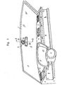
- a rear view mirror assembly is disposed at an upper central portion of a windshield 1 of a vehicle.
- a rear view mirror 25 is rotatably mounted on an inner surface of the windshield 1 through a support arm 15, a mounting member 14 and a first base member 3.
- the first base member 3 is cemented by an adhesive 2 to the windshield 1.
- the first base member 3 includes a plurality of screw holes therein, and a second base member 5 is fixed on the first base member 3 by a corresponding plurality of screws 29.
- the second base member 5 includes a mounting portion 271 which is disposed in the vicinity of an outer peripheral edge thereof, and is on a substantially flat horizontal surface.
- a hook 6 extends from an inner portion of the mounting portion 271.
- the hook 6 has-an inner peripheral edge and an upper surface, the inner peripheral edge defining an opening 4 within the second base member 5.
- the upper surface of the hook 6 has a plurality of second projections 8 and a plurality of second recesses 7 thereon.
- a spring 9 is defined within the opening 4 of the second base member 5.
- the spring 9 includes a cap 10, a plurality of first projections 11 and a plurality of first recesses 12.
- the cap 10 is fixed at a central portion of the spring 9, and includes a cavity 102 with an inner end 101 therein.
- the cavity 102 of the cap 10 includes a screw hole therein.
- the plurality of first projections 11 of the spring 9 extend outwardly in its radial direction, and engage with the plurality of second recesses 7 of the second base member 5. Therefore, the spring 9 engages securely with the second base member 5, so that the spring 9 cannot rotate in the opening 4 of the second base member 5. Further, the spring 9 can support a predetermined amount of a downward vertical force so that the spring 9 can break away from the hook 6, when more than the predetermined amount of the downward vertical force is applied to the spring 9.
- the mounting member 14 is disposed on the mounting portion 271 of the second base member 5.
- the mounting member 14 includes an upper peripheral edge 272 and a first socket portion 13.
- the upper peripheral edge 272 is in contact with the mounting portion 271 of the second base member 5, and the first socket portion 13 of the mounting member 14 is formed in a lower surface of the mounting member 14.
- the first socket portion 13 is formed in a semi-spherical concave shape, and has a first aperture 141 at the central portion of the mounting member 14.
- the support arm 15 is pivotally mounted on the first i 3 ocket portion 13 of the mounting member 14.
- the support arm 15 has an opposite end 24.
- the end 16 of the support arm 15 includes an outer surface and an inner surface.
- the outer surface of the support arm 15 has a first ball portion 161 thereon formed in a semi-spherical convex shape.
- the first ball portion 161 is mounted on the first socket portion 13 of the mounting member 14.
- the inner surface of the support arr 15 includes a second socket portion 162 which is formed in a semi-spherical concave shape.
- the inner surface of the support arm 15 defines a recess within the end 16 of the support arm 15, and a second aperture 21 is opened between the second socket portion 162 of the inner surface of the support arm 15 and the first ball portion 161 on the outer surface of the support arm 15.
- the second aperture 21 has an inner peripheral edge.
- a curved or second ball member 18 having an upper semi-spherical convex surface is slidably mounted on the second socket portion 162 of the supporting arm 15.
- the second ball member 18 has a third aperture 181 and a plurality of protrusions 22 on its convex surface.
- at least three protrusions 22 are disposed on the upper semi-spherical convex surface.
- the protrusions 22 are normally located within the inner peripheral edge of the second aperture 21.
- a bolt 19 is provided for securing the various components together.
- the bolt 19 includes a head portion on an end thereof adjacent the second ball member 18. The opposite end of the bolt 19 is inserted into the cavity 102 in the cap 10 of the spring 9.
- An intermediate shank portion of the bolt 19 extends through the third aperture 181 of the second ball member 18, the second aperture 21 of the support arm 15, and the first aperture 141 of the mounting member 14.
- a diameter of the second aperture 21 is greater than the diameter of the first aperture 141 and the third aperture 181, so that the support arm 15 is supported for universal movement. That is, the support member 15 can rotate about the vertical axis of the bolt 19 (Fig. 2), the protrusions 22 rotating within the second aperture 21.
- the support member 15 can also rotate about a central point 17 (Fig. 2) of the support arm 15 to an extent defined by the inner peripheral edge of the second aperture 21. Rotation about the central point 17 requires the inner surface of the support arm 15 to ride over the protrusions 22.
- the bolt 19 may be a screw or a rod.
- the opposite end of the bolt 19 is prevented from being inserted into the cavity 102 of the cap 10 more than a predetermined length by the inner end 101 of the cap 10, so that a bolt length defined between the cap 10 and the head portion of the bolt 19 is constant.
- the bolt length between the cap 10 and the head portion of the bolt 19 is greater than a sum of the thicknesses of the mounting member 14 around the first aperture 141, the supporting arm 15 around the second aperture 21, and the second ball member 18 around the third aperture 181. Therefore, the support arm 15 can move along the longitudinal axis of the bolt 19, as well as rotating about a central portion 17 of the support arm 15.
- the bolt 19 may be integral with the second ball member 18.
- the recess of the support arm 15 opens downward in a lower portion of the support arm 15, and a cover 23 is disposed within the recess. Therefore, the cover 23 covers the recess and improves the aesthetic appearance of the rear view mirror assembly.
- the opposite end of the support arm 15 includes a ball portion 24, and the ball portion 24 formed in a spherical ball shape.
- the ball portion 24 is rotatably received in a spherical socket portion 241 which is defined within the rear view mirror. 25.
- a first unit of the rear view mirror assembly includes the bolt 19, the spring 9, the mounting member 14, the support arm 15 and the second ball member 18.
- the bolt 19 unites the spring 9, the mounting member 14, the support arm 15 and the second ball member 18.
- the first unit of the rear view mirror assembly can break away from the second base member 5.
- a washer 20 is disposed between the cap 10 and the mounting member 14.
- the washer 20 is made of synthetic resin.
- the washer 20 includes a hole therein which is slightly smaller than a diameter of the bolt 19. Therefore, the washer 20 prevents the bolt 19 from moving easily in the hole of the washer 20, once the bolt 19 is inserted into the hole of the washer 20.
- the washer 20 and the bolt 19 can unite the mounting member 14, the support arm 15 and the second ball member 18, and then these components make up a second unit of the rear view mirror assembly.
- the second unit (I. e., mounting member 14, support arm 15 and second ball member 18, all of which are united by the bolt 19 and the washer 20) is attached to the spring 9 by threading the bolt 19 into the cop 10.
- the assembly of the second unit with the spring 9 forms the first unit.
- the spring 9 may be inserted within the second base member 5 when the second unit is attached to the spring.
- the plurality of protrusions 22 of the second ball member 18 are normally disposed in the second aperture 21 of the support arm 15, so that the plurality of protrusions 22 normally prevent the rotation of the support arm 15 about the central point 17. Therefore, it is convenient for a worker to install the second unit of the rear view mirror assembly on the spring 9, because these components of the second unit cannot change their positions due to the interlocked relation between the protrusions 22 and the second aperture 21 of the support arm 15. That is, the insertion of the protrusions 22 within the second aperture 21 temporarily maintains the components in position during assembly. As noted above, once assembled, the inner surface of the support arm 15 can ride over the protrusions 22 to permit rotation about the central point 17.
- the inner surface of the support arm 15 can ride on the protrusion 22 of the second ball member 18, when a force "F l " is applied to a central point 26 of the ball end 24 of the support arm 15.
- the support arm 15 rotates about a central point 17 of the support arm 15.
- the intermediate shank portion of the bolt 19 limits the movement of the support arm 15 to rotate within a space defined by the second aperture 21. That is, the inner peripheral edge of the second aperture 21 contacts the intermediate shank portion of the bolt 19 and thus limits the rotation of the support arm 15 about the central point 17.
- l 1 is a vertical length between the point 28 and the central point 26 of the ball end 24 for the rear view mirror 25.
- the point 28 is defined between the first ball portion 161 of the support arm 15 and an edge of the first socket portion 13 of the mounting member 14.
- a second moment "M 2 " in the clockwise direction about point 28 in Fig. 4 is calculated by the second formula (2) as follows:
- the spring 9 can break away from the hook 6 of the second base member 5. Concurrently the first unit of the rear view mirror assembly can break away when the spring 9 separates from the hook 6.
- the third moment M 3 in the clockwise direction about the point 27 is calculated by a fifth formula (5) as follows:
- l is a vertical length between the point 27 and the central point 26 of the rotation of the rear view mirror 25, and l 5 is a horizontal length between the point 27 and the point 26.
- the support arm 15 and the mounting member 14 can be rotated about the point 27, so that the upper edge 272 of the mounting member 14 separates partially from the mounting portion 271 of the second base member 5.
- both of the support arm 15 and the mounting member 14 are supported by the spring 9.
- a downward vertical force "F 6 " along the bolt 19 generates a fourth moment M 4 in the clockwise direction about the point 27.
- the fourth moment M 4 is calculated by the following sixth formula (6):
- t 4 is a horizontal length between the point 27 and the bolt 19.
- the spring 9 can break away from the hook 6 of the second base member 5. Therefore, the first unit of the rear view mirror assembly can break away.
- FIG. 8 A second embodiment of a rear view mirror assembly is shown in Figure 8.
- the second embodiment is similar to the first embodiment disclosed in Figure 2. However, the second embodiment has several differences disclosed hereunder
- a third base member 30 includes a cavity 441 defined therewithin.
- a spring 9 is disposed within the cavity 441 of the third base member 30, and is mounted on a hook 6 of the third base member 30.
- the spring 9 includes a base plate 39 at a central portion thereof.
- a bolt 38 extends downwardly from the base plate 39 of the spring 9, and the bolt 38 has a screw thread thereon.
- a mounting member 33 includes a third ball portion 32 at a lower surface thereof, and a fourth aperture 34 therein.
- the fourth aperture 34 is opened in the third ball portion 32, and the bolt 38 is inserted into the fourth aperture 34.
- the third ball portion 32 of the mounting member 33 is formed in a semi-spherical convex shape.
- a support arm 15 includes an end 35 having an outer surface and an inner surface thereof.
- a third socket portion 351 is formed on the outer surface of the support arm 15, and the third socket portion 351 is slidably mounted on the third ball portion 32 of the mounting member 33.
- the third socket portion 351 of the support arm 15 is formed in a semi-spherical socket concave shape, and a fifth aperture 37 is opened in the third socket portion 351 of the support arm 15.
- a diameter of the fifth aperture 37 of the support arm 15 is greater than a diameter of the fourth aperture 34 of the mounting member 33, and the bolt 38 is inserted into the fifth aperture 37 of the support arm 15.
- a fourth ball portion 352 is formed in the inner surface of the support arm 15, and has a semi-spherical convex shape.
- the fifth aperture 37 is opened in the fourth ball portion 352 of the support arm 15.
- a fourth socket member 40 is mounted on the fourth ball portion 352 of the support arm.
- the fourth socket member 40 includes an upper semi-spherical concave surface 401 thereon and a sixth aperture 402 which is opened in the upper semi-spherical concave surface 401 thereof.
- a diameter of the sixth aperture 402 of the fourth socket member 40 is smaller than the diameter of the fifth aperture 37 of the support arm 15, and the bolt 38 is inserted into the sixth aperture 402 of the fourth socket member 40, so that the support arm 15 can rotate about the bolt 38 within a space defined between the third ball portion 32 of the mounting member 33 and the upper semi-spherical concave surface 401 of the fourth socket member 40.
- a nut 41 is mounted on a lower surface of the fourth socket member 40, and the nut 41 engages with the screw thread of the bolt 38. Therefore, the nut 41 can support the fourth socket member 40, the support arm 15 and the mounting member 33 on the hook 6 of the third base member 30 through the bolt 38 and the spring 9.
- a first unit of the rear view mirror assembly includes the fourth socket member 40, the support arm 15, the mounting member 33, the spring 9 and the bolt 38.
- the fourth socket member 40 includes a second protrusion 42 on the upper semi-spherical concave surface 401 thereof, and the second protrusion 42 is disposed around the sixth aperture 402 of the fourth socket member 40.
- the second protrusion 42 of the fourth socket member is normally disposed within the fifth aperture 37 of the support arm 15, so that the support arm 15 cannot rotate easily about a central point 17 of a rotation of the support arm 15.
- the fourth ball portion 352 of the support arm 15 can ride over the second protrusion 42 of the fourth socket member 40, when a force "F is applied to the support arm 15.
- a third embodiment of a rear view mirror assembly is shown in Figure 9.
- the third embodiment is substantially similar to the second embodiment disclosed in Figure 8. However, the major difference between the second embodiment and the third embodiment is a nut 411.
- the nut 411 includes a cavity 413 and an inner end 412, and the cavity 413 is defined within the nut 411.
- the nut 411 has a screw hole therein, and a bolt 38 is inserted into the cavity 413.
- the inner end 412 of the nut 411 prevents a bolt 38 from being inserted into the nut 411 more than a predetermined length, so that a length defined between an upper surface of the nut 411 and a base plate 39 of a spring 9 is constant. Therefore, a bias force which is normally caused on the spring 9 is constant, and the nut 411 can support a fourth socket member 40, a support arm 15 and a mounting member 33 on a hook 6 of a third base member 30 through the spring 9 and the bolt 38.
- a first unit of the rear view mirror assembly includes the spring 9, the mounting member 33, the support arm 15, the fourth socket member 40, the nut 411 and the bolt 38.
- the present invention overcomes the shortcomings or the known art by providing a first unit of the rear view mirror assembly which can break away, when a force is applied to the rear view mirror in all directions of the rear view mirror. Further, assembly is facilitated by forming the components into a second sub-unit which is attached to the spring to form the first unit.
Abstract
Description
- The present invention relates to a rear view mirror assembly of r vehicle, and more particularly to improvements in a universally adjustable device disposed between a base member and a support arm of the rear view mirror assembly.
- An adjustable device disposed between a base member and a support arm of a rear view mirror is disclosed in Japanese Utility Model Laid-open No. Showa 58-24595. In this Japanese Utility Model Laid-open No. Showa 58-24595, the rear view mirror includes a support arm, a spring and a base member. The base member is cemented on an interior of a windshield, and includes a bar and a mounting portion. The spring includes a hooked end and a rear edge, and the hooked end being mounted on the bar of the base member. The rear edge of the spring is disposed on the mounting portion, and the support arm is fixed on the spring by a bolt.
- Further, the base member includes a slanted surface on a bottom surface thereof and the support arm includes an incline on an end thereof. As shown in FIG. 12 of Japanese Utility Model Laid-open No. Showa 58-24595, when a force "Pc" is applied to the rear view mirror, the support arm is moved downwardly and breaks away, because the incline of the support arm and the slanted surface of the base member prevent the support arm from resisting the force "Pc".
- Furthermore, this rear view mirror assembly includes a spherical ball portion disposed on an opposite end of the support arm, the ball portion being received within a socket portion of the rear view mirror.
- Therefore, this rear view mirror can be adjusted to its angle through the spherical ball portion and the socket portion of the rear view mirror. However, the range of the adjustment of this rear view mirror is rather small, because this rear view mirror includes only one adjustment device.
- Another adjustment device disposed between a windshield header and a support arm of a rear view mirror is disclosed in U.S. Patent No. 3,575,375.
- In this U. S. Patent 3,575,375, the rear view mirror assembly includes a first adjustment device and a second adjustment device. The first adjustment device includes a clamping plate and a spherical ball on one end of the support arm. The second adjustment device includes a stud adjustably mounted on an opposite end of the support arm. The rear view mirror is mounted on the stud. Thus, this rear view mirror assembly can be adjusted to a wide range of angular positions by the first adjustment device and the second adjustment device.
- Further, the ball on the support arm has a V-shaped notch so that the support arm can break away from the clamping plate when an excessive force is applied to the rear view mirror by rotating the support arm about the spherical ball. However, during assembly, it is necessary for a worker to pay attention to the desired distance between a mounting bracket for the entire assembly and the clamping plate, because the support arm cannot break away when a less than desired distance is defined between the mounting bracket and the clamping plate. It is further noted that the support arm cannot mount on the windshield header when a greater than desired distance is defined between a mounting bracket and the clamping plate. Thus, the device = disclosed in the '375 patent is relatively difficult to assemble.
- A rear view mirror having an adjustment device which is disposed between a body member of a vehicle and the rear view mirror is disclosed in U.S. Patent 3,471,115. This adjustment device includes a semi-spherical socket portion and a spring. The semi-spherical socket portion engages frictionally with a ball end of a support arm for the rear view mirror, and a spring biases the ball end into engagement with the semi-spherical socket portion. The rear view mirror can move universally about the adjustment device when a force is applied thereto. However, the rear view mirror cannot break away from its mounting bracket under an excessive force because the support arm of the rear view mirror is connected to the mounting bracket through the spring.
- U.S. Patent No. 3,425,657 discloses a rear view mirror assembly having a ball and socket joint. The ball includes a plurality of projections mating within grooves in the socket. The rear view mirror assembly, however, cannot break away from the windshield.
- The present invention has been developed in view of the foregoing background and to overcome the foregoing drawbacks. It is accordingly an object of this invention to provide a rear view mirror - assembly which is able to break away from a windshield, when more than a predetermined amount of a force is applied to the rear view mirror assembly in all directions of the rear view mirror.
- It is another object of the invention to provide a rear view mirror assembly which is able to be adjusted universally to a wide range of angular positions.
- Further, it is another object of the invention to provide a rear view mirror assembly which is relatively easier to assemble by enabling a worker to disregard a distance which is defined between a second ball member and a spring of the rear view mirror assembly, when the rear view mirror assembly is installed on the windshield.
- In order to accomplish the above-described objects, a rear view mirror assembly according to the present invention includes a base member and a first unit of the rear view mirror assembly. The first unit of the rear view mirror assembly includes a mounting member, a spring, a support arm, a second ball member, a bolt and a rear view mirror. The base member is preferably cemented to a windshield of a vehicle, and the base member has a hook and a mounting portion thereon.
- The mounting member is disposed on the mounting portion of the base member, and includes a first socket portion and a first aperture thereon. The first aperture is opened in the first socket portion. The spring is mounted on the hook of the base member, and the spring has an engagement device. The support arm includes an outer surface and an inner surface on an end thereof. The outer surface of the support arm is slidably mounted on the first socket portion of the mounting member, and the inner surface of the support arm includes a second socket portion. A second aperture is opened in both of the second socket portion of the inner surface and the outer surface. The rear view mirror is rotatably mounted. on an opposite end of the support arm.
- The second ball member is slidably mounted on the second socket portion of the support arm, and the second ball member is connected to an end of the bolt. The bolt is inserted into the second aperture of the support arm and the first aperture of the mounting member, and the other end of the bolt is engaged with the engagement device of the spring.
- Therefore, the components of the first unit of the rear view mirror assembly are united. The spring of the first unit of the rear view mirror assembly can support a predetermined amount of the downward vertical force on the hook of the base member, so that the first unit of the rear view mirror assembly can break away from the base member, when more than the predetermined amount of the downward vertical force is applied thereto.
- Further, the engagement device of the spring has an inner end therein, so that the inner end prevents the bolt from being inserted more than a predetermined length. Therefore, a length defined between the engagement device and the second ball member is constant. Accordingly, it is not necessary of a worker to pay any attention to the length during assembly.
- A diameter of the second aperture of the support arm is longer than a diameter of both the first aperture of the mounting member, so that the support arm can rotate about the bolt, and the support arm is capable of being universally adjusted to any angle in a wide range of angles.
- The above objects, features and advantages of the present invention will become more apparent from the description of the invention which follows, taken in conjunction with the accompanying drawings, wherein like reference numerals denote like elements, and wherein:
- FIG. 1 is a perspective view showing a rear view mirror assembly according to the present invention;
- FIG. 2 is an enlarged cross-sectional view of the rear view mirror assembly of a first embodiment, taken along the line iI-II in FIG. 1;
- FIG. 3 is an enlarged perspective view showing components of the rear view mirror assembly shown in FIG. 1 in a disassembled condition;
- FIG. 4 is a cross-sectional view of the rear view mirror assembly of Fig. 2, which shows the support arm rotated about a central
rotational point 17 of the rotation of the support arm in the clockwise direction in FIG. 2, when a force "F1" is applied to the support arm in the horizontal direction in FIG. 2; - FIG. 5 is a cross-sectional view of the rear view mirror assembly of Fig. 2, which shows the support arm rotated about the
central point 17 of the rotation of the support arm in the clockwise direction in an amount greater than the condition which is shown in FIG. 4; - FIG. 6 is a cross-sectional view of the rear view mirror assembly of Fig. 2, which shows the force "F 1" applied to the support arm along the line connecting the
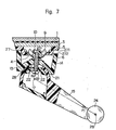
central point 17 of the rotation of the support arm to a central point for of the rotation of the rear view mirror; - FIG. 7 is a cross-sectional view of the rear view mirror assembly of Fig. 2, which shows the support arm rotated about a
contact point 27 between a mounting member and a base member in the clockwise direction; - FIG. 8 is an enlarged cross-sectional view of the rear view mirror assembly of a second embodiment, taken along the line II-II in FIG. 1; and
- FIG. 9 is an enlarged cross-sectional view of the rear view mirror assembly of a third embodiment, taken along the line II-II in FIG. 1.
- The present invention will be described in detail with reference to the accompanying drawings which illustrate different embodiments according to the present invention.
- Referring to Figure 1, a rear view mirror assembly is disposed at an upper central portion of a
windshield 1 of a vehicle. Arear view mirror 25 is rotatably mounted on an inner surface of thewindshield 1 through asupport arm 15, a mountingmember 14 and afirst base member 3. - As shown in Figure 2 and Figure 3, the
first base member 3 is cemented by an adhesive 2 to thewindshield 1. Thefirst base member 3 includes a plurality of screw holes therein, and asecond base member 5 is fixed on thefirst base member 3 by a corresponding plurality ofscrews 29. - The
second base member 5 includes a mountingportion 271 which is disposed in the vicinity of an outer peripheral edge thereof, and is on a substantially flat horizontal surface. Ahook 6 extends from an inner portion of the mountingportion 271. Thehook 6 has-an inner peripheral edge and an upper surface, the inner peripheral edge defining anopening 4 within thesecond base member 5. The upper surface of thehook 6 has a plurality ofsecond projections 8 and a plurality of second recesses 7 thereon. - A
spring 9 is defined within theopening 4 of thesecond base member 5. Thespring 9 includes acap 10, a plurality offirst projections 11 and a plurality offirst recesses 12. Thecap 10 is fixed at a central portion of thespring 9, and includes acavity 102 with aninner end 101 therein. Thecavity 102 of thecap 10 includes a screw hole therein. - The plurality of
first projections 11 of thespring 9 extend outwardly in its radial direction, and engage with the plurality of second recesses 7 of thesecond base member 5. Therefore, thespring 9 engages securely with thesecond base member 5, so that thespring 9 cannot rotate in theopening 4 of thesecond base member 5. Further, thespring 9 can support a predetermined amount of a downward vertical force so that thespring 9 can break away from thehook 6, when more than the predetermined amount of the downward vertical force is applied to thespring 9. - The mounting
member 14 is disposed on the mountingportion 271 of thesecond base member 5. The mountingmember 14 includes an upperperipheral edge 272 and afirst socket portion 13. The upperperipheral edge 272 is in contact with the mountingportion 271 of thesecond base member 5, and thefirst socket portion 13 of the mountingmember 14 is formed in a lower surface of the mountingmember 14. Thefirst socket portion 13 is formed in a semi-spherical concave shape, and has afirst aperture 141 at the central portion of the mountingmember 14. - The
support arm 15 is pivotally mounted on the first i3ocket portion 13 of the mountingmember 14. Thesupport arm 15 has anopposite end 24. Theend 16 of thesupport arm 15 includes an outer surface and an inner surface. The outer surface of thesupport arm 15 has afirst ball portion 161 thereon formed in a semi-spherical convex shape. Thefirst ball portion 161 is mounted on thefirst socket portion 13 of the mountingmember 14. The inner surface of the support arr 15 includes asecond socket portion 162 which is formed in a semi-spherical concave shape. The inner surface of thesupport arm 15 defines a recess within theend 16 of thesupport arm 15, and asecond aperture 21 is opened between thesecond socket portion 162 of the inner surface of thesupport arm 15 and thefirst ball portion 161 on the outer surface of thesupport arm 15. Thesecond aperture 21 has an inner peripheral edge. - A curved or
second ball member 18 having an upper semi-spherical convex surface is slidably mounted on thesecond socket portion 162 of the supportingarm 15. Thesecond ball member 18 has athird aperture 181 and a plurality ofprotrusions 22 on its convex surface. Preferably, at least threeprotrusions 22 are disposed on the upper semi-spherical convex surface. Theprotrusions 22 are normally located within the inner peripheral edge of thesecond aperture 21. - A
bolt 19 is provided for securing the various components together. Thebolt 19 includes a head portion on an end thereof adjacent thesecond ball member 18. The opposite end of thebolt 19 is inserted into thecavity 102 in thecap 10 of thespring 9. An intermediate shank portion of thebolt 19 extends through thethird aperture 181 of thesecond ball member 18, thesecond aperture 21 of thesupport arm 15, and thefirst aperture 141 of the mountingmember 14. A diameter of thesecond aperture 21 is greater than the diameter of thefirst aperture 141 and thethird aperture 181, so that thesupport arm 15 is supported for universal movement. That is, thesupport member 15 can rotate about the vertical axis of the bolt 19 (Fig. 2), theprotrusions 22 rotating within thesecond aperture 21. Thesupport member 15 can also rotate about a central point 17 (Fig. 2) of thesupport arm 15 to an extent defined by the inner peripheral edge of thesecond aperture 21. Rotation about thecentral point 17 requires the inner surface of thesupport arm 15 to ride over theprotrusions 22. - It should be apparent to one skilled in the art that the
bolt 19 may be a screw or a rod. - The opposite end of the
bolt 19 is prevented from being inserted into thecavity 102 of thecap 10 more than a predetermined length by theinner end 101 of thecap 10, so that a bolt length defined between thecap 10 and the head portion of thebolt 19 is constant. The bolt length between thecap 10 and the head portion of thebolt 19 is greater than a sum of the thicknesses of the mountingmember 14 around thefirst aperture 141, the supportingarm 15 around thesecond aperture 21, and thesecond ball member 18 around thethird aperture 181. Therefore, thesupport arm 15 can move along the longitudinal axis of thebolt 19, as well as rotating about acentral portion 17 of thesupport arm 15. - It will be apparent to one skilled in the art that the
bolt 19 may be integral with thesecond ball member 18. - The recess of the
support arm 15 opens downward in a lower portion of thesupport arm 15, and acover 23 is disposed within the recess. Therefore, thecover 23 covers the recess and improves the aesthetic appearance of the rear view mirror assembly. - The opposite end of the
support arm 15 includes aball portion 24, and theball portion 24 formed in a spherical ball shape. Theball portion 24 is rotatably received in aspherical socket portion 241 which is defined within the rear view mirror. 25. - A first unit of the rear view mirror assembly includes the
bolt 19, thespring 9, the mountingmember 14, thesupport arm 15 and thesecond ball member 18. In the first unit of the rear view mirror assembly, thebolt 19 unites thespring 9, the mountingmember 14, thesupport arm 15 and thesecond ball member 18. When more than the predetermined amount of the downward vertical force is applied to thespring 9, the first unit of the rear view mirror assembly can break away from thesecond base member 5. - A
washer 20 is disposed between thecap 10 and the mountingmember 14. Preferably, thewasher 20 is made of synthetic resin. Thewasher 20 includes a hole therein which is slightly smaller than a diameter of thebolt 19. Therefore, thewasher 20 prevents thebolt 19 from moving easily in the hole of thewasher 20, once thebolt 19 is inserted into the hole of thewasher 20. Further, thewasher 20 and thebolt 19 can unite the mountingmember 14, thesupport arm 15 and thesecond ball member 18, and then these components make up a second unit of the rear view mirror assembly. During assembly, the second unit (I. e., mountingmember 14,support arm 15 andsecond ball member 18, all of which are united by thebolt 19 and the washer 20) is attached to thespring 9 by threading thebolt 19 into thecop 10. The assembly of the second unit with thespring 9 forms the first unit. Thespring 9 may be inserted within thesecond base member 5 when the second unit is attached to the spring. - As shown in Figure 2, the plurality of
protrusions 22 of thesecond ball member 18 are normally disposed in thesecond aperture 21 of thesupport arm 15, so that the plurality ofprotrusions 22 normally prevent the rotation of thesupport arm 15 about thecentral point 17. Therefore, it is convenient for a worker to install the second unit of the rear view mirror assembly on thespring 9, because these components of the second unit cannot change their positions due to the interlocked relation between theprotrusions 22 and thesecond aperture 21 of thesupport arm 15. That is, the insertion of theprotrusions 22 within thesecond aperture 21 temporarily maintains the components in position during assembly. As noted above, once assembled, the inner surface of thesupport arm 15 can ride over theprotrusions 22 to permit rotation about thecentral point 17. - Description will be hereunder given of operation of the above-described embodiment.
- As shown in Figure 4, the inner surface of the
support arm 15 can ride on theprotrusion 22 of thesecond ball member 18, when a force "Fl" is applied to acentral point 26 of the ball end 24 of thesupport arm 15. As a result of the force "F1", thesupport arm 15 rotates about acentral point 17 of thesupport arm 15. The intermediate shank portion of thebolt 19 limits the movement of thesupport arm 15 to rotate within a space defined by thesecond aperture 21. That is, the inner peripheral edge of thesecond aperture 21 contacts the intermediate shank portion of thebolt 19 and thus limits the rotation of thesupport arm 15 about thecentral point 17. - When the force "F1" is continuously applied to the
support arm 15 in the horizontal direction in FIG. 4, a first moment M1 in the clockwise direction about apoint 28 is calculated by a first formula (1) as follows:
- In this first formula (1), ℓ1 is a vertical length between the
point 28 and thecentral point 26 of the ball end 24 for therear view mirror 25. Thepoint 28 is defined between thefirst ball portion 161 of thesupport arm 15 and an edge of thefirst socket portion 13 of the mountingmember 14. - A second moment "M2" in the clockwise direction about
point 28 in Fig. 4 is calculated by the second formula (2) as follows: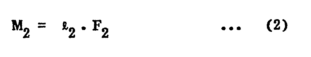
- In the second formula (2), ℓ2 is the horizontal length between
point 28 and thebolt 19, and "F2" is a downward vertical force on thebolt 19. The resiliency of thespring 9 resists the force "F2". - For equilibrium, M1 must equal M2. Therefore, the downward vertical force "F2" along the
bolt 19, which is applied to thespring 9, is calculated by a third formula (3) as follows: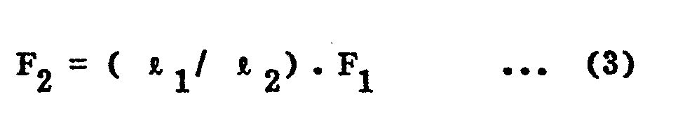
- In Figure 5, a force "F3" is applied to the
central point 26 and a downward vertical force "F4" is applied to thespring 9. If the force "F3" is larger than the force "F1", and a force "F4" is not larger than the predetermined downward vertical force, thesupport arm 15 is further rotated about thepoint 28. Thefirst ball portion 161 of thesupport arm 15 separates partially from thefirst socket portion 13 of the mountingmember 14, and thesupport arm 15 is supported by thespring 9. In this condition, the force "F4" is balanced with a bias force "F5" of thespring 9 so that the moments generated about thepoint 28 are equal. The force "F4" is calculated by a fourth formula (4) as follows:
- Next, if the force "F3" becomes larger, and the force "F4'' becomes larger than the predetermined amount of the downward vertical force, the
spring 9 can break away from thehook 6 of thesecond base member 5. Concurrently the first unit of the rear view mirror assembly can break away when thespring 9 separates from thehook 6. - As shown in Figure 6, when the force "Fl" is applied to the
support arm 15 along the line which connects thecentral point 26 to thecentral point 17 of thesupport arm 15, thesupport arm 15 cannot be rotated about thecentral point 17. - However, the vertical and horizontal components F1v, F1h of the force F1 cause a third moment M3 in the clockwise direction about a
point 27, thepoint 27 being defined between the mountingportion 271 of thesecond base member 5 and theupper edge 272 of the mountingmember 14. The third moment M3 in the clockwise direction about thepoint 27 is calculated by a fifth formula (5) as follows:
- In this fifth formula (5), ℓ is a vertical length between the
point 27 and thecentral point 26 of the rotation of therear view mirror 25, and ℓ5 is a horizontal length between thepoint 27 and thepoint 26. - Therefore, as shown in Figure 7, the
support arm 15 and the mountingmember 14 can be rotated about thepoint 27, so that theupper edge 272 of the mountingmember 14 separates partially from the mountingportion 271 of thesecond base member 5. In this case, both of thesupport arm 15 and the mountingmember 14 are supported by thespring 9. In Figure 7, a downward vertical force "F6" along thebolt 19 generates a fourth moment M4 in the clockwise direction about thepoint 27. The fourth moment M4 is calculated by the following sixth formula (6):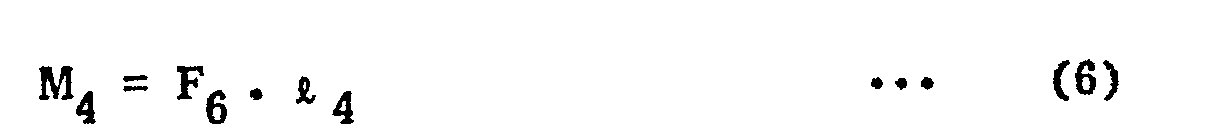
- In this sixth formula (6),
t 4 is a horizontal length between thepoint 27 and thebolt 19. - If M3 equals M4' then the force F6 along the
bolt 19 is balanced with a bias force "F7" of thespring 9 and calculated by a seventh formula (7) as follows:
- Next, if the force "F1" increases and the force "F6" becomes larger than the predetermined amount of the downward vertical force, the
spring 9 can break away from thehook 6 of thesecond base member 5. Therefore, the first unit of the rear view mirror assembly can break away. - A second embodiment of a rear view mirror assembly is shown in Figure 8. The second embodiment is similar to the first embodiment disclosed in Figure 2. However, the second embodiment has several differences disclosed hereunder
- A
third base member 30 includes acavity 441 defined therewithin. Aspring 9 is disposed within thecavity 441 of thethird base member 30, and is mounted on ahook 6 of thethird base member 30. Thespring 9 includes abase plate 39 at a central portion thereof. Abolt 38 extends downwardly from thebase plate 39 of thespring 9, and thebolt 38 has a screw thread thereon. ' - A mounting
member 33 includes a third ball portion 32 at a lower surface thereof, and afourth aperture 34 therein. Thefourth aperture 34 is opened in the third ball portion 32, and thebolt 38 is inserted into thefourth aperture 34. The third ball portion 32 of the mountingmember 33 is formed in a semi-spherical convex shape. - A
support arm 15 includes anend 35 having an outer surface and an inner surface thereof. Athird socket portion 351 is formed on the outer surface of thesupport arm 15, and thethird socket portion 351 is slidably mounted on the third ball portion 32 of the mountingmember 33. Thethird socket portion 351 of thesupport arm 15 is formed in a semi-spherical socket concave shape, and afifth aperture 37 is opened in thethird socket portion 351 of thesupport arm 15. A diameter of thefifth aperture 37 of thesupport arm 15 is greater than a diameter of thefourth aperture 34 of the mountingmember 33, and thebolt 38 is inserted into thefifth aperture 37 of thesupport arm 15. Afourth ball portion 352 is formed in the inner surface of thesupport arm 15, and has a semi-spherical convex shape. Thefifth aperture 37 is opened in thefourth ball portion 352 of thesupport arm 15. - A
fourth socket member 40 is mounted on thefourth ball portion 352 of the support arm. Thefourth socket member 40 includes an upper semi-sphericalconcave surface 401 thereon and asixth aperture 402 which is opened in the upper semi-sphericalconcave surface 401 thereof. A diameter of thesixth aperture 402 of thefourth socket member 40 is smaller than the diameter of thefifth aperture 37 of thesupport arm 15, and thebolt 38 is inserted into thesixth aperture 402 of thefourth socket member 40, so that thesupport arm 15 can rotate about thebolt 38 within a space defined between the third ball portion 32 of the mountingmember 33 and the upper semi-sphericalconcave surface 401 of thefourth socket member 40. - A
nut 41 is mounted on a lower surface of thefourth socket member 40, and thenut 41 engages with the screw thread of thebolt 38. Therefore, thenut 41 can support thefourth socket member 40, thesupport arm 15 and the mountingmember 33 on thehook 6 of thethird base member 30 through thebolt 38 and thespring 9. - A first unit of the rear view mirror assembly includes the
fourth socket member 40, thesupport arm 15, the mountingmember 33, thespring 9 and thebolt 38. - Further, the
fourth socket member 40 includes asecond protrusion 42 on the upper semi-sphericalconcave surface 401 thereof, and thesecond protrusion 42 is disposed around thesixth aperture 402 of thefourth socket member 40. Thesecond protrusion 42 of the fourth socket member is normally disposed within thefifth aperture 37 of thesupport arm 15, so that thesupport arm 15 cannot rotate easily about acentral point 17 of a rotation of thesupport arm 15. However, thefourth ball portion 352 of thesupport arm 15 can ride over thesecond protrusion 42 of thefourth socket member 40, when a force "F is applied to thesupport arm 15. N - A third embodiment of a rear view mirror assembly is shown in Figure 9. The third embodiment is substantially similar to the second embodiment disclosed in Figure 8. However, the major difference between the second embodiment and the third embodiment is a
nut 411. - The
nut 411 includes acavity 413 and aninner end 412, and thecavity 413 is defined within thenut 411. Thenut 411 has a screw hole therein, and abolt 38 is inserted into thecavity 413. Theinner end 412 of thenut 411 prevents abolt 38 from being inserted into thenut 411 more than a predetermined length, so that a length defined between an upper surface of thenut 411 and abase plate 39 of aspring 9 is constant. Therefore, a bias force which is normally caused on thespring 9 is constant, and thenut 411 can support afourth socket member 40, asupport arm 15 and a mountingmember 33 on ahook 6 of athird base member 30 through thespring 9 and thebolt 38. A first unit of the rear view mirror assembly includes thespring 9, the mountingmember 33, thesupport arm 15, thefourth socket member 40, thenut 411 and thebolt 38. - As described herein, the present invention overcomes the shortcomings or the known art by providing a first unit of the rear view mirror assembly which can break away, when a force is applied to the rear view mirror in all directions of the rear view mirror. Further, assembly is facilitated by forming the components into a second sub-unit which is attached to the spring to form the first unit.
- Further, techniques relating to the rear view mirror may be found in European Patent Applications filed by the present Applicants concurrently with the present Application, and all entitled "A REAR VIEW MIRROR ASSEMBLY".
- While the present invention has been described in its preferred embodiments, it is to be understood that the invention is not limited thereto, and may be otherwise embodied within the scope of the following claims.
Claims (10)
Applications Claiming Priority (8)
| Application Number | Priority Date | Filing Date | Title |
|---|---|---|---|
| JP1984111269U JPS6126648U (en) | 1984-07-23 | 1984-07-23 | Indoor mirror mounting structure |
| JP111270/84 | 1984-07-23 | ||
| JP1984111270U JPS6126649U (en) | 1984-07-23 | 1984-07-23 | Indoor mirror mounting structure |
| JP111269/84 | 1984-07-23 | ||
| JP1984111268U JPS6126647U (en) | 1984-07-23 | 1984-07-23 | Indoor mirror mounting structure |
| JP111268/84 | 1984-07-23 | ||
| JP128089/84 | 1984-08-24 | ||
| JP1984128089U JPS6142349U (en) | 1984-08-24 | 1984-08-24 | Indoor mirror mounting structure |
Publications (3)
| Publication Number | Publication Date |
|---|---|
| EP0169731A2 true EP0169731A2 (en) | 1986-01-29 |
| EP0169731A3 EP0169731A3 (en) | 1987-06-24 |
| EP0169731B1 EP0169731B1 (en) | 1989-10-04 |
Family
ID=27469893
Family Applications (4)
| Application Number | Title | Priority Date | Filing Date |
|---|---|---|---|
| EP19850305243 Expired EP0169731B1 (en) | 1984-07-23 | 1985-07-23 | A rear view mirror assembly |
| EP19850305245 Expired EP0169733B1 (en) | 1984-07-23 | 1985-07-23 | A rear view mirror assembly |
| EP19850305244 Expired EP0169732B1 (en) | 1984-07-23 | 1985-07-23 | A rear view mirror assembly |
| EP19850305246 Expired EP0169734B1 (en) | 1984-07-23 | 1985-07-23 | A rear view mirror assembly |
Family Applications After (3)
| Application Number | Title | Priority Date | Filing Date |
|---|---|---|---|
| EP19850305245 Expired EP0169733B1 (en) | 1984-07-23 | 1985-07-23 | A rear view mirror assembly |
| EP19850305244 Expired EP0169732B1 (en) | 1984-07-23 | 1985-07-23 | A rear view mirror assembly |
| EP19850305246 Expired EP0169734B1 (en) | 1984-07-23 | 1985-07-23 | A rear view mirror assembly |
Country Status (2)
| Country | Link |
|---|---|
| EP (4) | EP0169731B1 (en) |
| DE (4) | DE3573402D1 (en) |
Cited By (2)
| Publication number | Priority date | Publication date | Assignee | Title |
|---|---|---|---|---|
| DE4128768A1 (en) * | 1991-08-29 | 1993-03-04 | Austria Metall | SHOCK EQUIPMENT, ESPECIALLY FOR A MOTOR VEHICLE |
| FR2694639A1 (en) * | 1992-08-10 | 1994-02-11 | Rey Jean Yves | Electronic measurement device determining distance between two cars - uses reflected beam to determine distance and detect when car in front starts to move |
Families Citing this family (24)
| Publication number | Priority date | Publication date | Assignee | Title |
|---|---|---|---|---|
| DE3636495A1 (en) * | 1986-10-27 | 1988-04-28 | Bernhard Mittelhaeuser | REAR VIEW MIRROR FOR MOTOR VEHICLES |
| US6822563B2 (en) | 1997-09-22 | 2004-11-23 | Donnelly Corporation | Vehicle imaging system with accessory control |
| US5877897A (en) | 1993-02-26 | 1999-03-02 | Donnelly Corporation | Automatic rearview mirror, vehicle lighting control and vehicle interior monitoring system using a photosensor array |
| US6891563B2 (en) | 1996-05-22 | 2005-05-10 | Donnelly Corporation | Vehicular vision system |
| US7655894B2 (en) | 1996-03-25 | 2010-02-02 | Donnelly Corporation | Vehicular image sensing system |
| US6326613B1 (en) | 1998-01-07 | 2001-12-04 | Donnelly Corporation | Vehicle interior mirror assembly adapted for containing a rain sensor |
| US6124886A (en) | 1997-08-25 | 2000-09-26 | Donnelly Corporation | Modular rearview mirror assembly |
| US6278377B1 (en) | 1999-08-25 | 2001-08-21 | Donnelly Corporation | Indicator for vehicle accessory |
| US6445287B1 (en) | 2000-02-28 | 2002-09-03 | Donnelly Corporation | Tire inflation assistance monitoring system |
| US6420975B1 (en) | 1999-08-25 | 2002-07-16 | Donnelly Corporation | Interior rearview mirror sound processing system |
| US7480149B2 (en) | 2004-08-18 | 2009-01-20 | Donnelly Corporation | Accessory module for vehicle |
| WO2001064481A2 (en) | 2000-03-02 | 2001-09-07 | Donnelly Corporation | Video mirror systems incorporating an accessory module |
| WO2003065084A1 (en) | 2002-01-31 | 2003-08-07 | Donnelly Corporation | Vehicle accessory module |
| ES2391556T3 (en) | 2002-05-03 | 2012-11-27 | Donnelly Corporation | Object detection system for vehicles |
| US7526103B2 (en) | 2004-04-15 | 2009-04-28 | Donnelly Corporation | Imaging system for vehicle |
| WO2006063827A1 (en) | 2004-12-15 | 2006-06-22 | Magna Donnelly Electronics Naas Limited | An accessory module system for a vehicle window |
| WO2008024639A2 (en) | 2006-08-11 | 2008-02-28 | Donnelly Corporation | Automatic headlamp control system |
| US8925891B2 (en) * | 2011-09-14 | 2015-01-06 | Gentex Corporation | Reverse detach mounting system |
| CN102729897B (en) * | 2012-07-18 | 2016-06-29 | 重庆长安汽车股份有限公司 | A kind of automobile rear view mirror lens governor motion |
| US10190610B1 (en) | 2017-10-13 | 2019-01-29 | Gentex Corporation | Mounting assembly for rearview device |
| WO2019111234A1 (en) | 2017-12-08 | 2019-06-13 | Gentex Corporation | Pre-loaded two-lobe spring twist-on rearview mounting assembly |
| US10974650B2 (en) | 2017-12-11 | 2021-04-13 | Gentex Corporation | Rearview device mount and attachment method |
| JP7128959B2 (en) | 2018-10-02 | 2022-08-31 | ジェンテックス コーポレイション | Adjustable mounting mechanism for rearview mirror assembly |
| CN109131086B (en) * | 2018-10-23 | 2021-10-15 | 上海豫兴电子科技有限公司 | Control method and control system of vehicle-mounted camera |
Citations (6)
| Publication number | Priority date | Publication date | Assignee | Title |
|---|---|---|---|---|
| GB1231353A (en) * | 1969-05-29 | 1971-05-12 | ||
| US3601352A (en) * | 1969-01-13 | 1971-08-24 | Ford Motor Co | Breakaway rearview mirror mounting assembly |
| DE7232846U (en) * | 1974-02-28 | Hagus Metallwarenwerk Gmbh | Outside rearview mirror | |
| GB2046687A (en) * | 1979-03-28 | 1980-11-19 | Zipperle W | A motor vehicle mirror |
| DE3022082A1 (en) * | 1979-06-14 | 1981-01-08 | Braas Spegelindustri Ab | Releasable rear view mirror fixing - has base with triangle-shaped spring engaging with three lugs on releasable part |
| JPS5824595A (en) * | 1981-07-24 | 1983-02-14 | ザ・アツプジヨン・カンパニ− | Steroid compound and manufacture |
Family Cites Families (8)
| Publication number | Priority date | Publication date | Assignee | Title |
|---|---|---|---|---|
| DE7407610U (en) * | Dr.-Ing.H.C. F. Porsche Ag, 7000 Stuttgart | |||
| US3131251A (en) * | 1958-06-09 | 1964-04-28 | Libbey Owens Ford Glass Co | Mirror mounting assembly |
| DE1189398B (en) * | 1958-07-24 | 1965-03-18 | Ford Werke Ag | Device for directly attaching a rearview mirror to the windshield of a motor vehicle |
| DE2219500A1 (en) * | 1972-04-21 | 1973-10-31 | Albert & Co C | TWO-PIECE MOTOR VEHICLE REVIEW MIRROR |
| US3928894A (en) * | 1974-11-26 | 1975-12-30 | Illinois Tool Works | Adhesive mounting device |
| IE47816B1 (en) * | 1979-05-18 | 1984-06-27 | Donnelly Mirrors Ltd | Mounting assembly for a vehicle interior rear view mirror |
| US4254931A (en) * | 1979-06-25 | 1981-03-10 | Standard Mirror Company, Inc. | Rear view mirror mount for interior of automobile |
| FR2519918B1 (en) * | 1982-01-21 | 1985-12-20 | Manzoni Bouchot Sa | DEVICE FOR FIXING AN ACCESSORY, IN PARTICULAR A MIRROR ON A WINDSHIELD OR VEHICLE WINDOW |
-
1985
- 1985-07-23 DE DE8585305243T patent/DE3573402D1/en not_active Expired
- 1985-07-23 EP EP19850305243 patent/EP0169731B1/en not_active Expired
- 1985-07-23 EP EP19850305245 patent/EP0169733B1/en not_active Expired
- 1985-07-23 DE DE8585305245T patent/DE3573575D1/en not_active Expired
- 1985-07-23 DE DE8585305244T patent/DE3573403D1/en not_active Expired
- 1985-07-23 EP EP19850305244 patent/EP0169732B1/en not_active Expired
- 1985-07-23 DE DE8585305246T patent/DE3573576D1/en not_active Expired
- 1985-07-23 EP EP19850305246 patent/EP0169734B1/en not_active Expired
Patent Citations (6)
| Publication number | Priority date | Publication date | Assignee | Title |
|---|---|---|---|---|
| DE7232846U (en) * | 1974-02-28 | Hagus Metallwarenwerk Gmbh | Outside rearview mirror | |
| US3601352A (en) * | 1969-01-13 | 1971-08-24 | Ford Motor Co | Breakaway rearview mirror mounting assembly |
| GB1231353A (en) * | 1969-05-29 | 1971-05-12 | ||
| GB2046687A (en) * | 1979-03-28 | 1980-11-19 | Zipperle W | A motor vehicle mirror |
| DE3022082A1 (en) * | 1979-06-14 | 1981-01-08 | Braas Spegelindustri Ab | Releasable rear view mirror fixing - has base with triangle-shaped spring engaging with three lugs on releasable part |
| JPS5824595A (en) * | 1981-07-24 | 1983-02-14 | ザ・アツプジヨン・カンパニ− | Steroid compound and manufacture |
Cited By (2)
| Publication number | Priority date | Publication date | Assignee | Title |
|---|---|---|---|---|
| DE4128768A1 (en) * | 1991-08-29 | 1993-03-04 | Austria Metall | SHOCK EQUIPMENT, ESPECIALLY FOR A MOTOR VEHICLE |
| FR2694639A1 (en) * | 1992-08-10 | 1994-02-11 | Rey Jean Yves | Electronic measurement device determining distance between two cars - uses reflected beam to determine distance and detect when car in front starts to move |
Also Published As
| Publication number | Publication date |
|---|---|
| EP0169732B1 (en) | 1989-10-04 |
| EP0169731A3 (en) | 1987-06-24 |
| EP0169733A2 (en) | 1986-01-29 |
| EP0169733A3 (en) | 1987-07-15 |
| EP0169734A2 (en) | 1986-01-29 |
| EP0169731B1 (en) | 1989-10-04 |
| EP0169732A3 (en) | 1987-07-15 |
| EP0169733B1 (en) | 1989-10-11 |
| EP0169734A3 (en) | 1987-07-08 |
| DE3573402D1 (en) | 1989-11-09 |
| DE3573575D1 (en) | 1989-11-16 |
| DE3573403D1 (en) | 1989-11-09 |
| DE3573576D1 (en) | 1989-11-16 |
| EP0169732A2 (en) | 1986-01-29 |
| EP0169734B1 (en) | 1989-10-11 |
Similar Documents
| Publication | Publication Date | Title |
|---|---|---|
| EP0169731B1 (en) | A rear view mirror assembly | |
| US4645316A (en) | Rear view mirror assembly | |
| US4668059A (en) | Rear view mirror assembly | |
| JP3888672B2 (en) | Reflector movable automotive headlamp | |
| US7686274B2 (en) | Pivoting detent joint | |
| US4867408A (en) | Device for holding a mirror element for rearview mirror | |
| US4626086A (en) | Rear view mirror assembly | |
| KR100743503B1 (en) | Inside rearview mirror apparatus for vehicle | |
| EP0268442A2 (en) | Support and adjustment mechanism for vehicle headlamp | |
| US20190118713A1 (en) | Interior rearview mirror assembly | |
| US4626087A (en) | Rear view mirror assembly | |
| US5022748A (en) | Support for an external rearview mirror for motor vehicles | |
| US5761967A (en) | Mounting frame of a vehicle control pedal unit | |
| EP1043508A2 (en) | A ball joint for cable guide | |
| US6168277B1 (en) | Rearview mirror | |
| US4027548A (en) | Remote control mirror | |
| GB2032365A (en) | Rear view mirror for motor vehicles | |
| GB2248429A (en) | Vehicle sun visor mounting | |
| US5788205A (en) | Rearview mirror mount | |
| US4411403A (en) | Pivot support bracket for mirror assembly | |
| EP0659608B1 (en) | Mirror support bracket | |
| JPH0937191A (en) | Fall preventive device for television receiver | |
| JPS6036494Y2 (en) | Back mirror for vehicle | |
| KR970004074Y1 (en) | Hanger attaching method for vehicle sun-visor | |
| JPS6238257Y2 (en) |
Legal Events
| Date | Code | Title | Description |
|---|---|---|---|
| PUAI | Public reference made under article 153(3) epc to a published international application that has entered the european phase |
Free format text: ORIGINAL CODE: 0009012 |
|
| AK | Designated contracting states |
Designated state(s): DE FR GB |
|
| 17P | Request for examination filed |
Effective date: 19860613 |
|
| PUAL | Search report despatched |
Free format text: ORIGINAL CODE: 0009013 |
|
| AK | Designated contracting states |
Kind code of ref document: A3 Designated state(s): DE FR GB |
|
| 17Q | First examination report despatched |
Effective date: 19881216 |
|
| GRAA | (expected) grant |
Free format text: ORIGINAL CODE: 0009210 |
|
| AK | Designated contracting states |
Kind code of ref document: B1 Designated state(s): DE FR GB |
|
| ET | Fr: translation filed | ||
| REF | Corresponds to: |
Ref document number: 3573402 Country of ref document: DE Date of ref document: 19891109 |
|
| PLBE | No opposition filed within time limit |
Free format text: ORIGINAL CODE: 0009261 |
|
| STAA | Information on the status of an ep patent application or granted ep patent |
Free format text: STATUS: NO OPPOSITION FILED WITHIN TIME LIMIT |
|
| 26N | No opposition filed | ||
| PGFP | Annual fee paid to national office [announced via postgrant information from national office to epo] |
Ref country code: FR Payment date: 19930709 Year of fee payment: 9 |
|
| PGFP | Annual fee paid to national office [announced via postgrant information from national office to epo] |
Ref country code: GB Payment date: 19930712 Year of fee payment: 9 |
|
| PGFP | Annual fee paid to national office [announced via postgrant information from national office to epo] |
Ref country code: DE Payment date: 19930726 Year of fee payment: 9 |
|
| PG25 | Lapsed in a contracting state [announced via postgrant information from national office to epo] |
Ref country code: GB Effective date: 19940723 |
|
| GBPC | Gb: european patent ceased through non-payment of renewal fee |
Effective date: 19940723 |
|
| PG25 | Lapsed in a contracting state [announced via postgrant information from national office to epo] |
Ref country code: FR Effective date: 19950331 |
|
| PG25 | Lapsed in a contracting state [announced via postgrant information from national office to epo] |
Ref country code: DE Effective date: 19950401 |
|
| REG | Reference to a national code |
Ref country code: FR Ref legal event code: ST |