EP1043495A2 - Fuel feed apparatus - Google Patents
Fuel feed apparatus Download PDFInfo
- Publication number
- EP1043495A2 EP1043495A2 EP00107583A EP00107583A EP1043495A2 EP 1043495 A2 EP1043495 A2 EP 1043495A2 EP 00107583 A EP00107583 A EP 00107583A EP 00107583 A EP00107583 A EP 00107583A EP 1043495 A2 EP1043495 A2 EP 1043495A2
- Authority
- EP
- European Patent Office
- Prior art keywords
- fuel
- tank
- feed apparatus
- pump
- pressure regulator
- Prior art date
- Legal status (The legal status is an assumption and is not a legal conclusion. Google has not performed a legal analysis and makes no representation as to the accuracy of the status listed.)
- Granted
Links
- 239000000446 fuel Substances 0.000 title claims abstract description 163
- 239000002828 fuel tank Substances 0.000 claims abstract description 22
- 230000001105 regulatory effect Effects 0.000 claims description 2
- 238000004519 manufacturing process Methods 0.000 description 6
- 239000003502 gasoline Substances 0.000 description 2
- 229920003002 synthetic resin Polymers 0.000 description 2
- 239000000057 synthetic resin Substances 0.000 description 2
- 238000002485 combustion reaction Methods 0.000 description 1
- 230000000694 effects Effects 0.000 description 1
- 239000003350 kerosene Substances 0.000 description 1
- 238000000034 method Methods 0.000 description 1
- 238000012856 packing Methods 0.000 description 1
- 238000005192 partition Methods 0.000 description 1
- 230000002787 reinforcement Effects 0.000 description 1
- 238000011144 upstream manufacturing Methods 0.000 description 1
Images



Classifications
-
- F—MECHANICAL ENGINEERING; LIGHTING; HEATING; WEAPONS; BLASTING
- F02—COMBUSTION ENGINES; HOT-GAS OR COMBUSTION-PRODUCT ENGINE PLANTS
- F02M—SUPPLYING COMBUSTION ENGINES IN GENERAL WITH COMBUSTIBLE MIXTURES OR CONSTITUENTS THEREOF
- F02M37/00—Apparatus or systems for feeding liquid fuel from storage containers to carburettors or fuel-injection apparatus; Arrangements for purifying liquid fuel specially adapted for, or arranged on, internal-combustion engines
- F02M37/04—Feeding by means of driven pumps
- F02M37/08—Feeding by means of driven pumps electrically driven
- F02M37/10—Feeding by means of driven pumps electrically driven submerged in fuel, e.g. in reservoir
- F02M37/103—Mounting pumps on fuel tanks
-
- F—MECHANICAL ENGINEERING; LIGHTING; HEATING; WEAPONS; BLASTING
- F02—COMBUSTION ENGINES; HOT-GAS OR COMBUSTION-PRODUCT ENGINE PLANTS
- F02M—SUPPLYING COMBUSTION ENGINES IN GENERAL WITH COMBUSTIBLE MIXTURES OR CONSTITUENTS THEREOF
- F02M37/00—Apparatus or systems for feeding liquid fuel from storage containers to carburettors or fuel-injection apparatus; Arrangements for purifying liquid fuel specially adapted for, or arranged on, internal-combustion engines
- F02M37/04—Feeding by means of driven pumps
- F02M37/08—Feeding by means of driven pumps electrically driven
- F02M37/10—Feeding by means of driven pumps electrically driven submerged in fuel, e.g. in reservoir
- F02M37/106—Feeding by means of driven pumps electrically driven submerged in fuel, e.g. in reservoir the pump being installed in a sub-tank
Definitions
- This invention relates to an in-tank type fuel feed apparatus and, more particularly, it relates to a technology that can be effectively applied to a fuel feed apparatus of the type that is particularly adapted to be mounted to the bottom of a fuel tank.
- in-tank type fuel feed apparatus having a fuel pump and a strainer arranged inside a fuel tank like the ones disclosed in Japanese Patent Applications Laid-Open Nos. 10-213036 and 8-225023 are popularly used for motor bicycles and motor cars.
- Such in-tank type fuel feed apparatus may be classified into two groups.
- the first group includes a fuel feed apparatus as disclosed in Japanese Patent Application Laid-Open No. 10-213036 and illustrated in FIG. 5 of the accompanying drawings. It is adapted to be fitted to the bottom opening 52 of a fuel tank 51.
- the second group includes a fuel feed apparatus as disclosed in Japanese Patent Application Laid-Open No. 8-225023 and illustrated in FIG. 6 of the accompanying drawings. It is adapted to be placed on the bottom of a fuel tank 61.
- a sub-tank 54 is mounted onto a set plate 53.
- a fuel pump 55 is arranged in the sub-tank 54 by way of a pump holder 60.
- a suction port 55a is arranged at a lower portion of the pump 55.
- a fuel filter 56 is fitted to the port 55a.
- An oil feed pipe 57 is drawn out from an upper portion of the pump 55.
- the pipe 57 is linked to a vehicle side pipe 59 by way of an anti-fuel-flow valve 58.
- the pressure required to open the valve 58 from the side of the pump 55 is selected to be equal to a value greater than the sum of the pressure of fuel head and the internal pressure of the fuel tank 51 so that fuel may not flow out nor disperse by the siphoning phenomenon that may appear there.
- a reserve tank main body 63 is fitted to the bottom of fuel tank 61 by way of a bracket 62.
- a lid 64 is fitted to the top of the main body 63.
- a pump support table 65 is arranged inside the main body 63 and the lid 64 is provided with an opening 69 to correspond to the table 65.
- a curved projection 67 and a keep plate 68 are arranged at the opening 69 in order to hold a fuel pump 66 in position on the table 65.
- the pump 66 is pinched and secured by the curved projection 67 and the keep plate 68 between the lid 64 and the main body 63.
- the fuel pump 66 of a known fuel feed apparatus as illustrated in FIG. 6, shows a stability much greater than that of the apparatus of FIG. 5 because the pump 66 is supported by the pump support table 65.
- the pressure regulator that is arranged downstream relative to the fuel pump has to be disposed outside the reserve tank (sub-tank).
- the pressure regulator is arranged close to the fuel tank to eliminate the fuel return pipe, the returned fuel is fed to the outside of the sub-tank. Therefore, although a sub-tank is provided, the fuel inside has to be discharged outside the sub-tank to make the sub-tank useless, if partly.
- a fuel feed apparatus comprising a fuel pump arranged in a fuel tank, said apparatus being adapted to be mounted into said fuel tank through an opening of the bottom of said fuel tank, and a flange member having bottom wall plate section for closing said opening and a lateral wall section formed integrally with said bottom plate section, the internal space defined by said lateral wall section forms a sub-tank within said fuel tank.
- the flange member operates as a sub-tank to reduce the number of components and the number of steps of manufacturing the apparatus.
- a fuel feed apparatus may additionally comprise a strainer for purifying fuel and the fuel pump and the strainer may be arranged within said space.
- a fuel feed apparatus according to the invention may additionally comprise a pressure regulator and the fuel pump and the pressure regulator may be arranged within said space. In either case, the entire apparatus can be down-sized and the fuel feed apparatus can be provided in the form of a module that is simply mounted into the fuel tank.
- the pressure regulator may be of the so-called return-less type, also the fuel returned from the pressure regulator may be fed back into the sub-tank. Then, all the fuel returned by the pressure regulator is put back into the sub-tank so that all the fuel in the sub-tank can be used without wasting and the engine can be fed with fuel on a highly stable basis.
- a lid may be fitted to the top of said lateral wall of a fuel feed apparatus according to the invention so as to securely hold the fuel pump from above. Then, the fuel pump is secured both at the top and at the bottom to make the apparatus highly resistive against vibrations.
- a lid may be fitted to the top of said lateral wall of a fuel feed apparatus according to the invention and provided with a connecting member having a fuel flow path for connecting said fuel pump and said strainer.
- the lid operates as fuel flow path to further reduce the number of components and hence the entire size of the apparatus.
- the connecting member may be made to hold the fuel pump and the strainer from above. Then, both the fuel pump and the strainer are secured at the top to make the apparatus highly resistive against vibrations.
- a lid may be fitted to the top of said lateral wall of a fuel feed apparatus according to the invention and provided with a connecting member having a fuel flow path for connecting said fuel pump and said pressure regulator.
- the lid operates as fuel flow path to further reduce the number of components and hence the entire size of the apparatus.
- the connecting member may be made to hold the fuel pump and the pressure regulator from above. Then, both the fuel pump and the pressure regulator are secured at the top to make the apparatus highly resistive against vibrations.
- said lateral wall section may comprise a fuel in-take port having a labyrinth structure, with this arrangement, the fuel that has flown into the sub-tank would not flow out easily as the labyrinth blocks any fuel trying to flow out.
- FIG. 1 is a schematic cross sectional lateral view of the first embodiment of fuel feed apparatus according to the invention, illustrating how it is arranged in position.
- FIG. 2 is a partly broken schematic perspective view of the embodiment of fuel feed apparatus of FIG. 1.
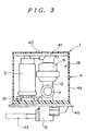
- FIG. 3 is a schematic cross sectional view of the embodiment of FIG. 1 taken along line A-A in FIG. 2.
- the fuel feed apparatus 1 of this embodiment (hereinafter referred to simply as "apparatus") is adapted to operate as in-tank type gasoline feed apparatus to be used with a motor bicycle.
- the apparatus 1 is fitted to an opening 3 formed through the bottom 2a of a fuel tank 2 from below.
- FIG. 2 it comprises a cup-shaped flange (flange member) 4 containing a fuel pump 5, a strainer 6 and a pressure regulator 7 along with other components and a lid 40 for closing the flange 4 and is realized in the form of a module.
- the apparatus 1 purifies fuel 42, sucked up by the pump 5, by means of the strainer 6 and regulate the pressure of the fuel to a predetermined level by means of the pressure regulator 7 before feeding it to the engine by way of a fuel feed pipe 43.
- the flange 4 is made of synthetic resin and comprises a bottom plate (bottom plate section) 4a and a lateral wall (lateral wall section) 4b formed integrally with the bottom plate 4a.
- the apparatus 1 is oil-tightly secured to the tank 2 as it is fitted to the opening 3 by way of a packing 8.
- the fuel feed apparatus 1 according to the invention is a module that can be installed by simply fitting it to the tank 2 and hence can remarkably improve the efficiency of mounting operation.
- the inside of the flange 4 of the apparatus 1 is empty and adapted to contain the pump 5 and other components and operate, at the same time, as a sub-tank 16.
- the flange 4 functions as reservoir so that the fuel 42 sucked up by the pump 5 is temporarily stored in the flange 4 in order to avoid any improper supply of fuel that can arise when the motor vehicle drives up a slope or is fiercely shaken.
- conventional sub-tanks comprise a plurality of components typically as shown in FIG. 5, that of apparatus 1 of the present invention comprises only a flange 4.
- the apparatus 1 has a reduced number of components to consequently reduce the manufacturing cost thereof.
- the flange 4 operates as a sub-tank means that all the major components of the apparatus 1 are contained in the sub-tank 16.
- the pump 5, the strainer 6 and the pressure regulator 7 are housed in the sub-tank 16 to consequently reduce the size of the module.
- a fuel in-take port 17 is formed at the lateral wall 4b of the flange 4 and operates to lead fuel 42 into the sub-tank 16.
- the inside of the port 17 has a labyrinth structure so that the fuel 42 would not flow out of the sub-tank 16.
- a partition wall 18 extends peripherally from an opening 17a to the inside of the flange 4 and the wall 18 and the inner wall of the flange 4 define a labyrinth 19.
- the lid 40 made of synthetic resin is arranged at the top of the flange 4 and has a connecting member 41 integrally formed with it on the lower surface of the lid 40 to produce a fuel flow path.
- the connecting member 41 comes into engagement with the pump 5 and the strainer 6, which are then connected to each other by the fuel flow path defined by the connecting member 41. Therefore, the pipe arranged in conventional fuel feed apparatus to connect the fuel pump and the strainer can be omitted to reduce the number of components and also that of manufacturing steps. Additionally, since the lid 40 and the member 41 are formed integrally, the apparatus 1 shows a reduced overall size.
- the fuel pump 5 and the strainer 6 are held at upper portions thereof by the lid 40.
- the lid 40 operates also as holder for holding the pump 5 and the strainer 6.
- the pump 5 and the strainer 6 of the apparatus 1 are secured both at the top and at the bottom to make them strongly resistive against vibrations without using a stay or a similar device to increase the number of components.
- a fuel suction port 10 is arranged under the pump 5 to draw fuel 42 from the bottom of the sub-tank 16.
- the port 10 is provided with a filter 13 to make fuel 42 get rid of coarse pieces of dirt.
- the apparatus 1 is used in a fuel feed system that may be a so-called return-less system.
- the fuel feed system using the apparatus 1 is provided with the pressure regulator 12 at the side of the fuel feed apparatus.
- a joint 12 is arranged under the strainer 6 and the pressure regulator 12 is connected to the joint 12 and also arranged within the sub-tank 16. All the fuel returned from the pressure regulator 7 is fed back to the sub-tank 16.
- the fuel feed apparatus 1 of the present invention is free from the drawback of the above described known apparatus of returning the fuel 42 in the sub-tank 16 to the outside of the sub-tank 16 so that it can feed fuel to the engine on a highly stable basis.
- the bottom of the joint 12 is connected to a fuel feed port 15 arranged at the bottom of the flange 4. Then, the port 15 is connected to a fuel pipe 43.
- the fuel 42 sucked up by the fuel pump 5 is fed to the port 15 by way of the connecting member 41, the strainer 6 and the joint 12. Then, the fuel 42 is fed from the port 15 to the engine by way of the pipe 43.
- the fuel 42 fed to the pipe 43 is regulated for pressure by the pressure regulator 7 and any excessive fuel produced by the pressure regulator 7 is returned into the sub-tank 16.
- the flange 4 that is fitted to the fuel tank 2 operates also as container for containing the fuel pump 5 and other components.
- the entire apparatus is realized in the form of a module where the flange 4 is made to operate as the sub-tank 16.
- the apparatus is downsized comprising a reduced number of components that can be manufactured with a reduced number of manufacturing steps.
- the lid 40 of the apparatus 1 is made to operate as connecting member 41 and also as support member for supporting the fuel pump 5 and other components to make the apparatus highly resistive against vibrations with a further reduce number of components. Still additionally, any excessive fuel is returned into the sub-tank 16 because the pressure regulator 7 is arranged inside the sub-tank 16. Thus, the fuel 42 in the sub-tank 16 can be fully exploited to supply fuel to the engine on a highly stable basis.
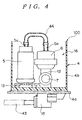
- FIG. 4 is a schematic cross sectional lateral view of Embodiment 2 of fuel feed apparatus according to the invention, illustrating how it is arranged in position, and corresponds to FIG. 3 of the first embodiment. Note that the components that are same as or similar to those of the first embodiment are respectively denoted by the same reference symbols and would not be described any further.
- the apparatus 100 is devoid of the lid 40 of apparatus 1 and the flange 4 is open at the top.
- the fuel pump 5 and the strainer 6 are connected to each other by means of a connecting tube 44 in place of the connecting member 41 of the first embodiment.
- Tube connecting sections 5a and 6a are arranged respectively at the top of the fuel pump 5 and at the top of the strainer 6 and, to be accurate, the tube 44 links both sections 5a and 6a. While the apparatus 100 is devoid of a lid 40 for holding the fuel pump 5 and the strainer 6 from above, the number of components of this embodiment can be further reduced.
- the pressure regulator 7 may be arranged upstream relative to the strainer 6 so that the pump 5 and the pressure regulator 7 (joint 12) may be connected to each other or held by a connecting member 41 or a connecting tube 44. If such is the case, the strainer 6 should not necessarily be arranged within the flange 4 as in the case of the pressure regulator 7 of any of the above embodiments.
- the present invention is described above in terms of a fuel feed apparatus of a motor bicycle, the applicability of the present invention is by no means limited to motor bicycles and it can equally be used as fuel feed apparatus that is applicable to motor cars, carts for carrying caddy bags in golf courses, lawn mowers, industrial machines, portable generators and other machines comprising an internal combustion engine as source of motive power.
- the fuel to be used with a fuel feed apparatus according to the invention is not limited to gasoline but may alternatively be light oil or kerosene oil.
- a fuel feed apparatus has the flange member having a bottom plate and a lateral wall, which is fitted to the bottom of the fuel tank from below and the internal space defined by the lateral wall operates as a sub-tank. Accordingly, it is possible to unify the flange member with the sub-tank, and to reduce a number of components and to improve manufacturing efficiency.
- the fuel pump and at least the strainer or the pressure regulator are arranged in said space to make it possible to downsize the entire apparatus.
- the fuel feed apparatus according to the invention and realized in the form of a module is mounted in position by simply fitting it to the fuel tank to greatly improve the manufacturing efficiency.
- the pressure regulator of the return-less type is arranged also within the above space, the fuel returned by the pressure regulator is brought into the sub-tank to completely use the fuel in the sub-tank without wasting it so that fuel may be fed to the engine on a highly stable basis.
- the fuel pump is secured both at the bottom and at the top of make it highly resistive against vibrations.
- the lid provides a fuel flow path that allows to further reduce the number of components and down-size the entire apparatus. Still additionally, as the connecting member holds the top of the fuel pump and that of the strainer or the pressure regulator, the fuel pump and the strainer or the pressure regulator are reliably secured at the top to make the entire apparatus highly resistive against vibrations.
- the inside of the fuel in-take port is made to have a labyrinth structure, the effect of preventing fuel from flowing out through the fuel in-take port can be further enhanced.
Landscapes
- Engineering & Computer Science (AREA)
- Chemical & Material Sciences (AREA)
- Combustion & Propulsion (AREA)
- Mechanical Engineering (AREA)
- General Engineering & Computer Science (AREA)
- Cooling, Air Intake And Gas Exhaust, And Fuel Tank Arrangements In Propulsion Units (AREA)
Abstract
Description
- This invention relates to an in-tank type fuel feed apparatus and, more particularly, it relates to a technology that can be effectively applied to a fuel feed apparatus of the type that is particularly adapted to be mounted to the bottom of a fuel tank.
- Conventionally, so-called in-tank type fuel feed apparatus having a fuel pump and a strainer arranged inside a fuel tank like the ones disclosed in Japanese Patent Applications Laid-Open Nos. 10-213036 and 8-225023 are popularly used for motor bicycles and motor cars. Such in-tank type fuel feed apparatus may be classified into two groups. The first group includes a fuel feed apparatus as disclosed in Japanese Patent Application Laid-Open No. 10-213036 and illustrated in FIG. 5 of the accompanying drawings. It is adapted to be fitted to the bottom opening 52 of a
fuel tank 51. The second group includes a fuel feed apparatus as disclosed in Japanese Patent Application Laid-Open No. 8-225023 and illustrated in FIG. 6 of the accompanying drawings. It is adapted to be placed on the bottom of afuel tank 61. - In the case of the apparatus of FIG. 5, a
sub-tank 54 is mounted onto aset plate 53. Afuel pump 55 is arranged in thesub-tank 54 by way of apump holder 60. Asuction port 55a is arranged at a lower portion of thepump 55. Afuel filter 56 is fitted to theport 55a. Anoil feed pipe 57 is drawn out from an upper portion of thepump 55. Thepipe 57 is linked to avehicle side pipe 59 by way of an anti-fuel-flow valve 58. The pressure required to open thevalve 58 from the side of thepump 55 is selected to be equal to a value greater than the sum of the pressure of fuel head and the internal pressure of thefuel tank 51 so that fuel may not flow out nor disperse by the siphoning phenomenon that may appear there. - On the other hand, in the case of the apparatus of FIG. 6, a reserve tank
main body 63 is fitted to the bottom offuel tank 61 by way of abracket 62. Alid 64 is fitted to the top of themain body 63. A pump support table 65 is arranged inside themain body 63 and thelid 64 is provided with anopening 69 to correspond to the table 65. Acurved projection 67 and akeep plate 68 are arranged at the opening 69 in order to hold afuel pump 66 in position on the table 65. Thus, thepump 66 is pinched and secured by thecurved projection 67 and the keepplate 68 between thelid 64 and themain body 63. - However, with a known fuel feed apparatus as illustrated in FIG. 5, where the
fuel pump 55 is rigidly secured onto thepump holder 60, thepump 55 is not highly stable relative to vibrations. A technique has also been proposed to rigidly secure thepump 55 to thesub-tank 54 or theset plate 53 by means of a stay in order to improve the stability of the pump. However, the stay does not satisfactorily improve the stability of the pump, while the arrangement of such a stay can increase the number of parts and hence the cost of the fuel feed apparatus. Additionally, if means are provided to satisfactorily stabilize the pump, a reinforcement having a considerable strength has to be used to by turn raise the size and the weight of the apparatus. - The
fuel pump 66 of a known fuel feed apparatus as illustrated in FIG. 6, on the other hand, shows a stability much greater than that of the apparatus of FIG. 5 because thepump 66 is supported by the pump support table 65. However, since thepump 66 is pinched and secured by thelid 64 and themain body 63 in the apparatus of FIG. 6, the pressure regulator that is arranged downstream relative to the fuel pump has to be disposed outside the reserve tank (sub-tank). Thus, if an apparatus as shown in FIG. 6 is applied to a so-called return-less system where the pressure regulator is arranged close to the fuel tank to eliminate the fuel return pipe, the returned fuel is fed to the outside of the sub-tank. Therefore, although a sub-tank is provided, the fuel inside has to be discharged outside the sub-tank to make the sub-tank useless, if partly. - It is the object of the present invention to provide a fuel feed apparatus that can supply fuel on a stable basis and is compact but resistive against vibrations.
- According to the invention, the above object is achieved by providing a fuel feed apparatus comprising a fuel pump arranged in a fuel tank, said apparatus being adapted to be mounted into said fuel tank through an opening of the bottom of said fuel tank, and a flange member having bottom wall plate section for closing said opening and a lateral wall section formed integrally with said bottom plate section, the internal space defined by said lateral wall section forms a sub-tank within said fuel tank.
- In a fuel feed apparatus according to the invention and having a configuration as described above, the flange member operates as a sub-tank to reduce the number of components and the number of steps of manufacturing the apparatus.
- A fuel feed apparatus according to the invention may additionally comprise a strainer for purifying fuel and the fuel pump and the strainer may be arranged within said space. Alternatively, a fuel feed apparatus according to the invention may additionally comprise a pressure regulator and the fuel pump and the pressure regulator may be arranged within said space. In either case, the entire apparatus can be down-sized and the fuel feed apparatus can be provided in the form of a module that is simply mounted into the fuel tank.
- Still additionally, the pressure regulator may be of the so-called return-less type, also the fuel returned from the pressure regulator may be fed back into the sub-tank. Then, all the fuel returned by the pressure regulator is put back into the sub-tank so that all the fuel in the sub-tank can be used without wasting and the engine can be fed with fuel on a highly stable basis.
- Meanwhile, a lid may be fitted to the top of said lateral wall of a fuel feed apparatus according to the invention so as to securely hold the fuel pump from above. Then, the fuel pump is secured both at the top and at the bottom to make the apparatus highly resistive against vibrations.
- Alternatively, a lid may be fitted to the top of said lateral wall of a fuel feed apparatus according to the invention and provided with a connecting member having a fuel flow path for connecting said fuel pump and said strainer. With this arrangement, the lid operates as fuel flow path to further reduce the number of components and hence the entire size of the apparatus. If such is the case, the connecting member may be made to hold the fuel pump and the strainer from above. Then, both the fuel pump and the strainer are secured at the top to make the apparatus highly resistive against vibrations.
- Still alternatively, a lid may be fitted to the top of said lateral wall of a fuel feed apparatus according to the invention and provided with a connecting member having a fuel flow path for connecting said fuel pump and said pressure regulator. With this arrangement, the lid operates as fuel flow path to further reduce the number of components and hence the entire size of the apparatus. If such is the case, the connecting member may be made to hold the fuel pump and the pressure regulator from above. Then, both the fuel pump and the pressure regulator are secured at the top to make the apparatus highly resistive against vibrations.
- Still additionally, said lateral wall section may comprise a fuel in-take port having a labyrinth structure, with this arrangement, the fuel that has flown into the sub-tank would not flow out easily as the labyrinth blocks any fuel trying to flow out.
- The above-described and other objects and novel feature of the present invention will become apparent more fully from the description of the following specification in conjunction with the accompanying drawings.
-
- FIG. 1 is a schematic cross sectional lateral view of Embodiment 1 of fuel feed apparatus according to the invention, illustrating how it is arranged in position.
- FIG. 2 is a partly broken schematic perspective view of the embodiment of fuel feed apparatus of FIG. 1.
- FIG. 3 is a schematic cross sectional view of the embodiment of FIG. 1 taken along line A-A in FIG. 2.
- FIG. 4 is a schematic cross sectional lateral view of Embodiment 2 of fuel feed apparatus according to the invention, illustrating how it is arranged in position.
- FIG. 5 is a schematic cross sectional lateral view of a known fuel feed apparatus.
- FIG. 6 is a schematic cross sectional lateral view of another known fuel feed apparatus.
-
- Now, the present invention will be described by referring to the accompanying drawings that illustrate preferred embodiments of the invention.
- FIG. 1 is a schematic cross sectional lateral view of the first embodiment of fuel feed apparatus according to the invention, illustrating how it is arranged in position. FIG. 2 is a partly broken schematic perspective view of the embodiment of fuel feed apparatus of FIG. 1. FIG. 3 is a schematic cross sectional view of the embodiment of FIG. 1 taken along line A-A in FIG. 2.
- The fuel feed apparatus 1 of this embodiment (hereinafter referred to simply as "apparatus") is adapted to operate as in-tank type gasoline feed apparatus to be used with a motor bicycle. As shown in FIG. 1, the apparatus 1 is fitted to an
opening 3 formed through thebottom 2a of a fuel tank 2 from below. As shown in FIG. 2, it comprises a cup-shaped flange (flange member) 4 containing afuel pump 5, astrainer 6 and apressure regulator 7 along with other components and alid 40 for closing theflange 4 and is realized in the form of a module. The apparatus 1 purifiesfuel 42, sucked up by thepump 5, by means of thestrainer 6 and regulate the pressure of the fuel to a predetermined level by means of thepressure regulator 7 before feeding it to the engine by way of afuel feed pipe 43. - The
flange 4 is made of synthetic resin and comprises a bottom plate (bottom plate section) 4a and a lateral wall (lateral wall section) 4b formed integrally with thebottom plate 4a. The apparatus 1 is oil-tightly secured to the tank 2 as it is fitted to theopening 3 by way of apacking 8. Thus, the fuel feed apparatus 1 according to the invention is a module that can be installed by simply fitting it to the tank 2 and hence can remarkably improve the efficiency of mounting operation. - The inside of the
flange 4 of the apparatus 1 is empty and adapted to contain thepump 5 and other components and operate, at the same time, as a sub-tank 16. In other words, theflange 4 functions as reservoir so that thefuel 42 sucked up by thepump 5 is temporarily stored in theflange 4 in order to avoid any improper supply of fuel that can arise when the motor vehicle drives up a slope or is fiercely shaken. While conventional sub-tanks comprise a plurality of components typically as shown in FIG. 5, that of apparatus 1 of the present invention comprises only aflange 4. Thus, the apparatus 1 has a reduced number of components to consequently reduce the manufacturing cost thereof. - The fact that the
flange 4 operates as a sub-tank means that all the major components of the apparatus 1 are contained in the sub-tank 16. In other words, in a fuel feed apparatus 1 according to the present invention, thepump 5, thestrainer 6 and thepressure regulator 7 are housed in the sub-tank 16 to consequently reduce the size of the module. - A fuel in-
take port 17 is formed at thelateral wall 4b of theflange 4 and operates to leadfuel 42 into the sub-tank 16. The inside of theport 17 has a labyrinth structure so that thefuel 42 would not flow out of the sub-tank 16. More specifically, apartition wall 18 extends peripherally from an opening 17a to the inside of theflange 4 and thewall 18 and the inner wall of theflange 4 define alabyrinth 19. Thus, with this arrangement, thefuel 42 that has flown into the sub-tank 16 would not flow out easily as thelabyrinth 19 blocks any fuel trying to flow out. - As shown in FIGS. 2 and 3, the
lid 40 made of synthetic resin is arranged at the top of theflange 4 and has a connectingmember 41 integrally formed with it on the lower surface of thelid 40 to produce a fuel flow path. Thus as thelid 40 is fitted to theflange 4, the connectingmember 41 comes into engagement with thepump 5 and thestrainer 6, which are then connected to each other by the fuel flow path defined by the connectingmember 41. Therefore, the pipe arranged in conventional fuel feed apparatus to connect the fuel pump and the strainer can be omitted to reduce the number of components and also that of manufacturing steps. Additionally, since thelid 40 and themember 41 are formed integrally, the apparatus 1 shows a reduced overall size. - The
fuel pump 5 and thestrainer 6 are held at upper portions thereof by thelid 40. In other words, thelid 40 operates also as holder for holding thepump 5 and thestrainer 6. Thus, thepump 5 and thestrainer 6 of the apparatus 1 are secured both at the top and at the bottom to make them strongly resistive against vibrations without using a stay or a similar device to increase the number of components. - A
fuel suction port 10 is arranged under thepump 5 to drawfuel 42 from the bottom of the sub-tank 16. Theport 10 is provided with afilter 13 to makefuel 42 get rid of coarse pieces of dirt. - On the other hand, the apparatus 1 is used in a fuel feed system that may be a so-called return-less system. In other words, the fuel feed system using the apparatus 1 is provided with the
pressure regulator 12 at the side of the fuel feed apparatus. A joint 12 is arranged under thestrainer 6 and thepressure regulator 12 is connected to the joint 12 and also arranged within the sub-tank 16. All the fuel returned from thepressure regulator 7 is fed back to the sub-tank 16. Thus, the fuel feed apparatus 1 of the present invention is free from the drawback of the above described known apparatus of returning thefuel 42 in the sub-tank 16 to the outside of the sub-tank 16 so that it can feed fuel to the engine on a highly stable basis. - The bottom of the joint 12 is connected to a
fuel feed port 15 arranged at the bottom of theflange 4. Then, theport 15 is connected to afuel pipe 43. Thus, thefuel 42 sucked up by thefuel pump 5 is fed to theport 15 by way of the connectingmember 41, thestrainer 6 and the joint 12. Then, thefuel 42 is fed from theport 15 to the engine by way of thepipe 43. Thefuel 42 fed to thepipe 43 is regulated for pressure by thepressure regulator 7 and any excessive fuel produced by thepressure regulator 7 is returned into the sub-tank 16. - Thus, as described above, with a fuel feed apparatus 1 according to the invention, the
flange 4 that is fitted to the fuel tank 2 operates also as container for containing thefuel pump 5 and other components. Additionally, the entire apparatus is realized in the form of a module where theflange 4 is made to operate as the sub-tank 16. As a result, the apparatus is downsized comprising a reduced number of components that can be manufactured with a reduced number of manufacturing steps. - Additionally, the
lid 40 of the apparatus 1 is made to operate as connectingmember 41 and also as support member for supporting thefuel pump 5 and other components to make the apparatus highly resistive against vibrations with a further reduce number of components. Still additionally, any excessive fuel is returned into the sub-tank 16 because thepressure regulator 7 is arranged inside the sub-tank 16. Thus, thefuel 42 in the sub-tank 16 can be fully exploited to supply fuel to the engine on a highly stable basis. - Now, Embodiment 2 of
fuel feed apparatus 100 according to the invention will be described below. FIG. 4 is a schematic cross sectional lateral view of Embodiment 2 of fuel feed apparatus according to the invention, illustrating how it is arranged in position, and corresponds to FIG. 3 of the first embodiment. Note that the components that are same as or similar to those of the first embodiment are respectively denoted by the same reference symbols and would not be described any further. - The
apparatus 100 is devoid of thelid 40 of apparatus 1 and theflange 4 is open at the top. Thefuel pump 5 and thestrainer 6 are connected to each other by means of a connectingtube 44 in place of the connectingmember 41 of the first embodiment.Tube connecting sections fuel pump 5 and at the top of thestrainer 6 and, to be accurate, thetube 44 links bothsections apparatus 100 is devoid of alid 40 for holding thefuel pump 5 and thestrainer 6 from above, the number of components of this embodiment can be further reduced. - Detailed description has hereinabove been given of the invention achieved by the present inventor with reference to the embodiments. However, the present invention should not be limited to the embodiments described above and may be variously modified within the scope not departing from the gist.
- For example, while the
fuel pump 5 and thestrainer 6 are connected by the connectingmember 41 or the connectingtube 44 in any of the above embodiments, thepressure regulator 7 may be arranged upstream relative to thestrainer 6 so that thepump 5 and the pressure regulator 7 (joint 12) may be connected to each other or held by a connectingmember 41 or a connectingtube 44. If such is the case, thestrainer 6 should not necessarily be arranged within theflange 4 as in the case of thepressure regulator 7 of any of the above embodiments. - Additionally, while the present invention is described above in terms of a fuel feed apparatus of a motor bicycle, the applicability of the present invention is by no means limited to motor bicycles and it can equally be used as fuel feed apparatus that is applicable to motor cars, carts for carrying caddy bags in golf courses, lawn mowers, industrial machines, portable generators and other machines comprising an internal combustion engine as source of motive power. Still additionally, the fuel to be used with a fuel feed apparatus according to the invention is not limited to gasoline but may alternatively be light oil or kerosene oil.
- As described above in detail, a fuel feed apparatus according to the invention has the flange member having a bottom plate and a lateral wall, which is fitted to the bottom of the fuel tank from below and the internal space defined by the lateral wall operates as a sub-tank. Accordingly, it is possible to unify the flange member with the sub-tank, and to reduce a number of components and to improve manufacturing efficiency.
- According to the invention, the fuel pump and at least the strainer or the pressure regulator are arranged in said space to make it possible to downsize the entire apparatus. Then, the fuel feed apparatus according to the invention and realized in the form of a module is mounted in position by simply fitting it to the fuel tank to greatly improve the manufacturing efficiency.
- Additionally, as the pressure regulator of the return-less type is arranged also within the above space, the fuel returned by the pressure regulator is brought into the sub-tank to completely use the fuel in the sub-tank without wasting it so that fuel may be fed to the engine on a highly stable basis.
- On the other hand, as a lid is arranged at the top of the lateral wall to hold the fuel pump from above, the fuel pump is secured both at the bottom and at the top of make it highly resistive against vibrations.
- Additionally, as a connecting member having a fuel flow path in the inside and operating to link the fuel pump and the strainer or the pressure regulator is arranged at the top of the lateral wall, the lid provides a fuel flow path that allows to further reduce the number of components and down-size the entire apparatus. Still additionally, as the connecting member holds the top of the fuel pump and that of the strainer or the pressure regulator, the fuel pump and the strainer or the pressure regulator are reliably secured at the top to make the entire apparatus highly resistive against vibrations.
- Finally, if the inside of the fuel in-take port is made to have a labyrinth structure, the effect of preventing fuel from flowing out through the fuel in-take port can be further enhanced.
Claims (11)
- A fuel feed apparatus comprising:a fuel pump arranged in a fuel tank;said apparatus being adapted to be mounted into said fuel tank through an opening of the bottom of said fuel tank; anda flange member having bottom wall plate section for closing said opening and a lateral wall section formed integrally with said bottom plate section;the internal space defined by said lateral wall section providing a sub-tank within said fuel tank.
- A fuel feed apparatus according to claim 1, further comprising a strainer for purifying fuel, said fuel pump and said strainer being arranged within said space.
- A fuel feed apparatus according to claim 1, further comprising a pressure regulator for regulating the fuel supply pressure, said fuel pump and said pressure regulator being arranged within said space.
- A fuel feed apparatus according to claim 3, wherein said pressure regulator is of the return-less type.
- A fuel feed apparatus according to claim 3 or 4, wherein the fuel returned from said pressure regulator is fed back into said sub-tank.
- A fuel feed apparatus according to any of claims 1 through 5, further comprising a lid to be fitted to an upper portion of said lateral wall section, said lid being adapted to hold said fuel pump from above.
- A fuel feed apparatus according to claim 2, further comprising a lid to be fitted to an upper portion of said lateral wall section, said lid having a connecting member provided with a fuel flow path connecting said fuel pump and said strainer.
- A fuel feed apparatus according to claim 7, wherein said connecting member is adapted to hold said fuel pump and said strainer from above.
- A fuel feed apparatus according to claim 3 or 4, further comprising a lid to be fitted to an upper portion of said lateral wall section, said lid having a connecting member provided with a fuel flow path connecting said fuel pump and said pressure regulator.
- A fuel feed apparatus according to claim 9, wherein said connecting member is adapted to hold said fuel pump and said pressure regulator from above.
- A fuel feed apparatus according to any of claims 1 through 10, wherein said lateral wall section comprises a fuel in-take port having a labyrinth structure.
Applications Claiming Priority (2)
| Application Number | Priority Date | Filing Date | Title |
|---|---|---|---|
| JP10321199 | 1999-04-09 | ||
| JP10321199A JP4248075B2 (en) | 1999-04-09 | 1999-04-09 | Fuel supply device |
Publications (3)
| Publication Number | Publication Date |
|---|---|
| EP1043495A2 true EP1043495A2 (en) | 2000-10-11 |
| EP1043495A3 EP1043495A3 (en) | 2001-03-07 |
| EP1043495B1 EP1043495B1 (en) | 2005-08-10 |
Family
ID=14348182
Family Applications (1)
| Application Number | Title | Priority Date | Filing Date |
|---|---|---|---|
| EP20000107583 Expired - Lifetime EP1043495B1 (en) | 1999-04-09 | 2000-04-07 | Fuel feed apparatus |
Country Status (4)
| Country | Link |
|---|---|
| EP (1) | EP1043495B1 (en) |
| JP (1) | JP4248075B2 (en) |
| CN (1) | CN1153902C (en) |
| TW (1) | TW493037B (en) |
Cited By (8)
| Publication number | Priority date | Publication date | Assignee | Title |
|---|---|---|---|---|
| WO2003044357A1 (en) * | 2001-11-20 | 2003-05-30 | Mitsubishi Denki Kabushiki Kaisha | Fuel supply system for vehicle |
| US6863814B2 (en) | 2002-06-28 | 2005-03-08 | Denko Corporation | In-tank type fuel feed apparatus |
| US7717466B2 (en) * | 2004-01-30 | 2010-05-18 | Yamaha Hatsudoki Kabushiki Kaisha | Mounting structure for fuel pump of vehicle engine and vehicle installing the same |
| WO2011086039A1 (en) * | 2010-01-13 | 2011-07-21 | Emitec Gesellschaft Für Emissionstechnologie Mbh | Device having a tank and a delivery unit for reductants |
| WO2011160836A1 (en) * | 2010-06-22 | 2011-12-29 | Robert Seuffer Gmbh & Co. Kg | Tank module for a liquid tank |
| WO2012126548A1 (en) * | 2011-03-21 | 2012-09-27 | Albonair Gmbh | Exhaust gas post treatment system |
| EP2706208A1 (en) * | 2012-09-05 | 2014-03-12 | Magneti Marelli S.p.A. | A fluid feeding device for an exhaust system of an internal combustion diesel engine provided with exhaust gas after-treatment |
| US11125196B2 (en) * | 2019-05-10 | 2021-09-21 | Walbro Llc | Bottom mount fuel pump assembly |
Families Citing this family (13)
| Publication number | Priority date | Publication date | Assignee | Title |
|---|---|---|---|---|
| JP2000301958A (en) * | 1999-04-16 | 2000-10-31 | Mitsuba Corp | Fuel supply device |
| CN1270279C (en) | 2001-05-21 | 2006-08-16 | 世嘉股份有限公司 | Image processing apparatus and game apparatus |
| JP4563920B2 (en) * | 2005-10-31 | 2010-10-20 | 本田技研工業株式会社 | Fuel supply device |
| JP4785576B2 (en) * | 2006-03-17 | 2011-10-05 | 株式会社ケーヒン | Fuel supply system for motorcycles |
| JP4575335B2 (en) * | 2006-06-30 | 2010-11-04 | 本田技研工業株式会社 | Fuel tank |
| KR100799770B1 (en) | 2006-08-31 | 2008-02-01 | (주)모토닉 | Fuel supply device for gas fuel vehicle |
| JP2008075528A (en) * | 2006-09-21 | 2008-04-03 | Keihin Corp | Mounting structure of fuel supply device for motorcycle |
| JP4944568B2 (en) * | 2006-10-26 | 2012-06-06 | 株式会社ケーヒン | Fuel supply device |
| JP5284160B2 (en) * | 2009-03-30 | 2013-09-11 | 本田技研工業株式会社 | Fuel supply device |
| DE102010004614B4 (en) | 2010-01-13 | 2025-03-13 | Vitesco Technologies GmbH | Device for providing liquid reducing agent |
| CN101898508A (en) * | 2010-08-03 | 2010-12-01 | 力帆实业(集团)股份有限公司 | Oil locking tank |
| JP2012087728A (en) * | 2010-10-21 | 2012-05-10 | Nifco Inc | Fuel filter case and fuel filter device |
| CN113771615B (en) * | 2021-09-01 | 2022-12-09 | 江苏耀坤液压股份有限公司 | High cleanliness steel oil tank for engineering machinery |
Citations (2)
| Publication number | Priority date | Publication date | Assignee | Title |
|---|---|---|---|---|
| JPH08225023A (en) | 1995-12-07 | 1996-09-03 | Nifco Inc | Swirling tank device for automobile fuel tank |
| JPH10213036A (en) | 1997-01-31 | 1998-08-11 | Mitsubishi Electric Corp | Vehicle fuel supply system |
Family Cites Families (5)
| Publication number | Priority date | Publication date | Assignee | Title |
|---|---|---|---|---|
| US5511957A (en) * | 1994-09-27 | 1996-04-30 | Walbro Corporation | High capacity fuel pump and filter combination |
| DE19508978C2 (en) * | 1995-03-13 | 1997-02-13 | Daimler Benz Ag | Fuel tank for motor vehicles |
| DE19531424A1 (en) * | 1995-08-26 | 1997-02-27 | Bosch Gmbh Robert | Fuel extraction equipment for fuel tanks, with underside insertion |
| DE19605952A1 (en) * | 1996-02-17 | 1997-08-21 | Bosch Gmbh Robert | Quick-change filter for internal combustion engine fuel supply |
| US6065452A (en) * | 1997-11-19 | 2000-05-23 | Mitsubishi Denki Kabushiki Kaisha | Fuel feeder for vehicles |
-
1999
- 1999-04-09 JP JP10321199A patent/JP4248075B2/en not_active Expired - Fee Related
-
2000
- 2000-03-29 TW TW89105774A patent/TW493037B/en not_active IP Right Cessation
- 2000-04-07 EP EP20000107583 patent/EP1043495B1/en not_active Expired - Lifetime
- 2000-04-07 CN CNB001049852A patent/CN1153902C/en not_active Expired - Fee Related
Patent Citations (2)
| Publication number | Priority date | Publication date | Assignee | Title |
|---|---|---|---|---|
| JPH08225023A (en) | 1995-12-07 | 1996-09-03 | Nifco Inc | Swirling tank device for automobile fuel tank |
| JPH10213036A (en) | 1997-01-31 | 1998-08-11 | Mitsubishi Electric Corp | Vehicle fuel supply system |
Cited By (13)
| Publication number | Priority date | Publication date | Assignee | Title |
|---|---|---|---|---|
| WO2003044357A1 (en) * | 2001-11-20 | 2003-05-30 | Mitsubishi Denki Kabushiki Kaisha | Fuel supply system for vehicle |
| US6863814B2 (en) | 2002-06-28 | 2005-03-08 | Denko Corporation | In-tank type fuel feed apparatus |
| US7717466B2 (en) * | 2004-01-30 | 2010-05-18 | Yamaha Hatsudoki Kabushiki Kaisha | Mounting structure for fuel pump of vehicle engine and vehicle installing the same |
| RU2542193C2 (en) * | 2010-01-13 | 2015-02-20 | Эмитек Гезельшафт Фюр Эмиссионстехнологи Мбх | Device with reservoir and supply device for reducing agent |
| WO2011086039A1 (en) * | 2010-01-13 | 2011-07-21 | Emitec Gesellschaft Für Emissionstechnologie Mbh | Device having a tank and a delivery unit for reductants |
| WO2011086038A1 (en) * | 2010-01-13 | 2011-07-21 | Emitec Gesellschaft Für Emissionstechnologie Mbh | Device having a tank and a delivery unit for reductants |
| US10041392B2 (en) | 2010-01-13 | 2018-08-07 | Emitec Gesellschaft Fuer Emissionstechnologie Mbh | Apparatus having a tank and a delivery unit for reducing agent |
| US9840958B2 (en) | 2010-01-13 | 2017-12-12 | Emitec Gesellschaft Fuer Emissionstechnologie Mbh | Apparatus having a tank and a delivery unit for reducing agent |
| US9074610B2 (en) | 2010-06-22 | 2015-07-07 | Seuffer gmbH & Co. KG | Tank module for a liquid tank |
| WO2011160836A1 (en) * | 2010-06-22 | 2011-12-29 | Robert Seuffer Gmbh & Co. Kg | Tank module for a liquid tank |
| WO2012126548A1 (en) * | 2011-03-21 | 2012-09-27 | Albonair Gmbh | Exhaust gas post treatment system |
| EP2706208A1 (en) * | 2012-09-05 | 2014-03-12 | Magneti Marelli S.p.A. | A fluid feeding device for an exhaust system of an internal combustion diesel engine provided with exhaust gas after-treatment |
| US11125196B2 (en) * | 2019-05-10 | 2021-09-21 | Walbro Llc | Bottom mount fuel pump assembly |
Also Published As
| Publication number | Publication date |
|---|---|
| TW493037B (en) | 2002-07-01 |
| CN1153902C (en) | 2004-06-16 |
| JP4248075B2 (en) | 2009-04-02 |
| EP1043495A3 (en) | 2001-03-07 |
| EP1043495B1 (en) | 2005-08-10 |
| CN1270279A (en) | 2000-10-18 |
| JP2000297713A (en) | 2000-10-24 |
Similar Documents
| Publication | Publication Date | Title |
|---|---|---|
| EP1043495B1 (en) | Fuel feed apparatus | |
| US6260543B1 (en) | Fuel delivery module with integrated filter | |
| JP5571366B2 (en) | Filter device | |
| US5951050A (en) | Integral reservoir for tank | |
| US7451745B2 (en) | Fuel tank for motorcycle | |
| US5341842A (en) | Bottom mount fuel tank module for an automobile | |
| KR101131326B1 (en) | Vehicle fuel supply device and fuel filter structure | |
| US6719539B1 (en) | Fuel feeder | |
| KR100359702B1 (en) | Fuel Injection Device for Backbone Type Autobicycle | |
| CN102030061A (en) | Scooter-type vehicle | |
| US7150260B2 (en) | Integrated air induction system | |
| JP2003176762A (en) | Fuel hose mounting structure for fuel injection engine | |
| JP2002527677A (en) | Fuel feed module | |
| EP1045132B1 (en) | Fuel feed apparatus | |
| US20050087175A1 (en) | Air-fuel mixing and delivery apparatus for an internal combustion engine | |
| EP1600625B1 (en) | Vehicle fuel supply construction | |
| CN1300902A (en) | Fuel supplier for IC engine of vehicle | |
| EP1980478B1 (en) | Motorcycle | |
| JP2003148267A (en) | Vehicle fuel pump unit | |
| JP4442997B2 (en) | Fuel supply device | |
| JP3726174B2 (en) | Fuel injection device for motorcycles | |
| JP2000301958A (en) | Fuel supply device | |
| EP1045133A2 (en) | Fuel feed apparatus | |
| JP2000297717A (en) | Fuel supply device | |
| JP4079546B2 (en) | Fuel supply device |
Legal Events
| Date | Code | Title | Description |
|---|---|---|---|
| PUAI | Public reference made under article 153(3) epc to a published international application that has entered the european phase |
Free format text: ORIGINAL CODE: 0009012 |
|
| AK | Designated contracting states |
Kind code of ref document: A2 Designated state(s): FR IT |
|
| AX | Request for extension of the european patent |
Free format text: AL;LT;LV;MK;RO;SI |
|
| PUAL | Search report despatched |
Free format text: ORIGINAL CODE: 0009013 |
|
| AK | Designated contracting states |
Kind code of ref document: A3 Designated state(s): AT BE CH CY DE DK ES FI FR GB GR IE IT LI LU MC NL PT SE |
|
| AX | Request for extension of the european patent |
Free format text: AL;LT;LV;MK;RO;SI |
|
| 17P | Request for examination filed |
Effective date: 20010831 |
|
| AKX | Designation fees paid |
Free format text: FR IT |
|
| 17Q | First examination report despatched |
Effective date: 20040705 |
|
| REG | Reference to a national code |
Ref country code: DE Ref legal event code: 8566 |
|
| GRAP | Despatch of communication of intention to grant a patent |
Free format text: ORIGINAL CODE: EPIDOSNIGR1 |
|
| GRAS | Grant fee paid |
Free format text: ORIGINAL CODE: EPIDOSNIGR3 |
|
| GRAA | (expected) grant |
Free format text: ORIGINAL CODE: 0009210 |
|
| AK | Designated contracting states |
Kind code of ref document: B1 Designated state(s): FR IT |
|
| ET | Fr: translation filed | ||
| PLBE | No opposition filed within time limit |
Free format text: ORIGINAL CODE: 0009261 |
|
| STAA | Information on the status of an ep patent application or granted ep patent |
Free format text: STATUS: NO OPPOSITION FILED WITHIN TIME LIMIT |
|
| 26N | No opposition filed |
Effective date: 20060511 |
|
| PGFP | Annual fee paid to national office [announced via postgrant information from national office to epo] |
Ref country code: FR Payment date: 20080312 Year of fee payment: 9 |
|
| PGFP | Annual fee paid to national office [announced via postgrant information from national office to epo] |
Ref country code: IT Payment date: 20080428 Year of fee payment: 9 |
|
| REG | Reference to a national code |
Ref country code: FR Ref legal event code: ST Effective date: 20091231 |
|
| PG25 | Lapsed in a contracting state [announced via postgrant information from national office to epo] |
Ref country code: FR Free format text: LAPSE BECAUSE OF NON-PAYMENT OF DUE FEES Effective date: 20091222 |
|
| PG25 | Lapsed in a contracting state [announced via postgrant information from national office to epo] |
Ref country code: IT Free format text: LAPSE BECAUSE OF NON-PAYMENT OF DUE FEES Effective date: 20090407 |