EP1043271A1 - Vorrichtung zur Teiloxidation von Kohlenwasserstoffen - Google Patents
Vorrichtung zur Teiloxidation von Kohlenwasserstoffen Download PDFInfo
- Publication number
- EP1043271A1 EP1043271A1 EP00201138A EP00201138A EP1043271A1 EP 1043271 A1 EP1043271 A1 EP 1043271A1 EP 00201138 A EP00201138 A EP 00201138A EP 00201138 A EP00201138 A EP 00201138A EP 1043271 A1 EP1043271 A1 EP 1043271A1
- Authority
- EP
- European Patent Office
- Prior art keywords
- synthesis gas
- catalyst bed
- reactors
- collection vessel
- partial oxidation
- Prior art date
- Legal status (The legal status is an assumption and is not a legal conclusion. Google has not performed a legal analysis and makes no representation as to the accuracy of the status listed.)
- Withdrawn
Links
Images


Classifications
-
- C—CHEMISTRY; METALLURGY
- C01—INORGANIC CHEMISTRY
- C01B—NON-METALLIC ELEMENTS; COMPOUNDS THEREOF; METALLOIDS OR COMPOUNDS THEREOF NOT COVERED BY SUBCLASS C01C
- C01B3/00—Hydrogen; Gaseous mixtures containing hydrogen; Separation of hydrogen from mixtures containing it; Purification of hydrogen
- C01B3/02—Production of hydrogen or of gaseous mixtures containing a substantial proportion of hydrogen
- C01B3/32—Production of hydrogen or of gaseous mixtures containing a substantial proportion of hydrogen by reaction of gaseous or liquid organic compounds with gasifying agents, e.g. water, carbon dioxide, air
- C01B3/34—Production of hydrogen or of gaseous mixtures containing a substantial proportion of hydrogen by reaction of gaseous or liquid organic compounds with gasifying agents, e.g. water, carbon dioxide, air by reaction of hydrocarbons with gasifying agents
- C01B3/38—Production of hydrogen or of gaseous mixtures containing a substantial proportion of hydrogen by reaction of gaseous or liquid organic compounds with gasifying agents, e.g. water, carbon dioxide, air by reaction of hydrocarbons with gasifying agents using catalysts
- C01B3/386—Catalytic partial combustion
-
- B—PERFORMING OPERATIONS; TRANSPORTING
- B01—PHYSICAL OR CHEMICAL PROCESSES OR APPARATUS IN GENERAL
- B01J—CHEMICAL OR PHYSICAL PROCESSES, e.g. CATALYSIS OR COLLOID CHEMISTRY; THEIR RELEVANT APPARATUS
- B01J8/00—Chemical or physical processes in general, conducted in the presence of fluids and solid particles; Apparatus for such processes
- B01J8/02—Chemical or physical processes in general, conducted in the presence of fluids and solid particles; Apparatus for such processes with stationary particles, e.g. in fixed beds
- B01J8/0242—Chemical or physical processes in general, conducted in the presence of fluids and solid particles; Apparatus for such processes with stationary particles, e.g. in fixed beds the fluid flow within the bed being predominantly vertical
-
- B—PERFORMING OPERATIONS; TRANSPORTING
- B01—PHYSICAL OR CHEMICAL PROCESSES OR APPARATUS IN GENERAL
- B01J—CHEMICAL OR PHYSICAL PROCESSES, e.g. CATALYSIS OR COLLOID CHEMISTRY; THEIR RELEVANT APPARATUS
- B01J8/00—Chemical or physical processes in general, conducted in the presence of fluids and solid particles; Apparatus for such processes
- B01J8/02—Chemical or physical processes in general, conducted in the presence of fluids and solid particles; Apparatus for such processes with stationary particles, e.g. in fixed beds
- B01J8/0278—Feeding reactive fluids
-
- C—CHEMISTRY; METALLURGY
- C01—INORGANIC CHEMISTRY
- C01B—NON-METALLIC ELEMENTS; COMPOUNDS THEREOF; METALLOIDS OR COMPOUNDS THEREOF NOT COVERED BY SUBCLASS C01C
- C01B3/00—Hydrogen; Gaseous mixtures containing hydrogen; Separation of hydrogen from mixtures containing it; Purification of hydrogen
- C01B3/02—Production of hydrogen or of gaseous mixtures containing a substantial proportion of hydrogen
- C01B3/32—Production of hydrogen or of gaseous mixtures containing a substantial proportion of hydrogen by reaction of gaseous or liquid organic compounds with gasifying agents, e.g. water, carbon dioxide, air
- C01B3/323—Catalytic reaction of gaseous or liquid organic compounds other than hydrocarbons with gasifying agents
-
- B—PERFORMING OPERATIONS; TRANSPORTING
- B01—PHYSICAL OR CHEMICAL PROCESSES OR APPARATUS IN GENERAL
- B01J—CHEMICAL OR PHYSICAL PROCESSES, e.g. CATALYSIS OR COLLOID CHEMISTRY; THEIR RELEVANT APPARATUS
- B01J2208/00—Processes carried out in the presence of solid particles; Reactors therefor
- B01J2208/00008—Controlling the process
- B01J2208/00017—Controlling the temperature
- B01J2208/00477—Controlling the temperature by thermal insulation means
- B01J2208/00495—Controlling the temperature by thermal insulation means using insulating materials or refractories
-
- B—PERFORMING OPERATIONS; TRANSPORTING
- B01—PHYSICAL OR CHEMICAL PROCESSES OR APPARATUS IN GENERAL
- B01J—CHEMICAL OR PHYSICAL PROCESSES, e.g. CATALYSIS OR COLLOID CHEMISTRY; THEIR RELEVANT APPARATUS
- B01J2208/00—Processes carried out in the presence of solid particles; Reactors therefor
- B01J2208/00796—Details of the reactor or of the particulate material
- B01J2208/00805—Details of the particulate material
- B01J2208/00814—Details of the particulate material the particulate material being provides in prefilled containers
-
- B—PERFORMING OPERATIONS; TRANSPORTING
- B01—PHYSICAL OR CHEMICAL PROCESSES OR APPARATUS IN GENERAL
- B01J—CHEMICAL OR PHYSICAL PROCESSES, e.g. CATALYSIS OR COLLOID CHEMISTRY; THEIR RELEVANT APPARATUS
- B01J2208/00—Processes carried out in the presence of solid particles; Reactors therefor
- B01J2208/00796—Details of the reactor or of the particulate material
- B01J2208/00823—Mixing elements
- B01J2208/00831—Stationary elements
- B01J2208/00849—Stationary elements outside the bed, e.g. baffles
-
- B—PERFORMING OPERATIONS; TRANSPORTING
- B01—PHYSICAL OR CHEMICAL PROCESSES OR APPARATUS IN GENERAL
- B01J—CHEMICAL OR PHYSICAL PROCESSES, e.g. CATALYSIS OR COLLOID CHEMISTRY; THEIR RELEVANT APPARATUS
- B01J2208/00—Processes carried out in the presence of solid particles; Reactors therefor
- B01J2208/02—Processes carried out in the presence of solid particles; Reactors therefor with stationary particles
- B01J2208/021—Processes carried out in the presence of solid particles; Reactors therefor with stationary particles comprising a plurality of beds with flow of reactants in parallel
-
- C—CHEMISTRY; METALLURGY
- C01—INORGANIC CHEMISTRY
- C01B—NON-METALLIC ELEMENTS; COMPOUNDS THEREOF; METALLOIDS OR COMPOUNDS THEREOF NOT COVERED BY SUBCLASS C01C
- C01B2203/00—Integrated processes for the production of hydrogen or synthesis gas
- C01B2203/02—Processes for making hydrogen or synthesis gas
- C01B2203/0205—Processes for making hydrogen or synthesis gas containing a reforming step
- C01B2203/0227—Processes for making hydrogen or synthesis gas containing a reforming step containing a catalytic reforming step
- C01B2203/0233—Processes for making hydrogen or synthesis gas containing a reforming step containing a catalytic reforming step the reforming step being a steam reforming step
-
- C—CHEMISTRY; METALLURGY
- C01—INORGANIC CHEMISTRY
- C01B—NON-METALLIC ELEMENTS; COMPOUNDS THEREOF; METALLOIDS OR COMPOUNDS THEREOF NOT COVERED BY SUBCLASS C01C
- C01B2203/00—Integrated processes for the production of hydrogen or synthesis gas
- C01B2203/02—Processes for making hydrogen or synthesis gas
- C01B2203/025—Processes for making hydrogen or synthesis gas containing a partial oxidation step
- C01B2203/0261—Processes for making hydrogen or synthesis gas containing a partial oxidation step containing a catalytic partial oxidation step [CPO]
-
- C—CHEMISTRY; METALLURGY
- C01—INORGANIC CHEMISTRY
- C01B—NON-METALLIC ELEMENTS; COMPOUNDS THEREOF; METALLOIDS OR COMPOUNDS THEREOF NOT COVERED BY SUBCLASS C01C
- C01B2203/00—Integrated processes for the production of hydrogen or synthesis gas
- C01B2203/08—Methods of heating or cooling
- C01B2203/0805—Methods of heating the process for making hydrogen or synthesis gas
- C01B2203/0838—Methods of heating the process for making hydrogen or synthesis gas by heat exchange with exothermic reactions, other than by combustion of fuel
- C01B2203/0844—Methods of heating the process for making hydrogen or synthesis gas by heat exchange with exothermic reactions, other than by combustion of fuel the non-combustive exothermic reaction being another reforming reaction as defined in groups C01B2203/02 - C01B2203/0294
-
- C—CHEMISTRY; METALLURGY
- C01—INORGANIC CHEMISTRY
- C01B—NON-METALLIC ELEMENTS; COMPOUNDS THEREOF; METALLOIDS OR COMPOUNDS THEREOF NOT COVERED BY SUBCLASS C01C
- C01B2203/00—Integrated processes for the production of hydrogen or synthesis gas
- C01B2203/08—Methods of heating or cooling
- C01B2203/0872—Methods of cooling
- C01B2203/0883—Methods of cooling by indirect heat exchange
-
- C—CHEMISTRY; METALLURGY
- C01—INORGANIC CHEMISTRY
- C01B—NON-METALLIC ELEMENTS; COMPOUNDS THEREOF; METALLOIDS OR COMPOUNDS THEREOF NOT COVERED BY SUBCLASS C01C
- C01B2203/00—Integrated processes for the production of hydrogen or synthesis gas
- C01B2203/10—Catalysts for performing the hydrogen forming reactions
- C01B2203/1005—Arrangement or shape of catalyst
- C01B2203/1029—Catalysts in the form of a foam
-
- C—CHEMISTRY; METALLURGY
- C01—INORGANIC CHEMISTRY
- C01B—NON-METALLIC ELEMENTS; COMPOUNDS THEREOF; METALLOIDS OR COMPOUNDS THEREOF NOT COVERED BY SUBCLASS C01C
- C01B2203/00—Integrated processes for the production of hydrogen or synthesis gas
- C01B2203/10—Catalysts for performing the hydrogen forming reactions
- C01B2203/1041—Composition of the catalyst
- C01B2203/1047—Group VIII metal catalysts
- C01B2203/1064—Platinum group metal catalysts
-
- C—CHEMISTRY; METALLURGY
- C01—INORGANIC CHEMISTRY
- C01B—NON-METALLIC ELEMENTS; COMPOUNDS THEREOF; METALLOIDS OR COMPOUNDS THEREOF NOT COVERED BY SUBCLASS C01C
- C01B2203/00—Integrated processes for the production of hydrogen or synthesis gas
- C01B2203/10—Catalysts for performing the hydrogen forming reactions
- C01B2203/1041—Composition of the catalyst
- C01B2203/1082—Composition of support materials
-
- C—CHEMISTRY; METALLURGY
- C01—INORGANIC CHEMISTRY
- C01B—NON-METALLIC ELEMENTS; COMPOUNDS THEREOF; METALLOIDS OR COMPOUNDS THEREOF NOT COVERED BY SUBCLASS C01C
- C01B2203/00—Integrated processes for the production of hydrogen or synthesis gas
- C01B2203/12—Feeding the process for making hydrogen or synthesis gas
- C01B2203/1205—Composition of the feed
-
- C—CHEMISTRY; METALLURGY
- C01—INORGANIC CHEMISTRY
- C01B—NON-METALLIC ELEMENTS; COMPOUNDS THEREOF; METALLOIDS OR COMPOUNDS THEREOF NOT COVERED BY SUBCLASS C01C
- C01B2203/00—Integrated processes for the production of hydrogen or synthesis gas
- C01B2203/12—Feeding the process for making hydrogen or synthesis gas
- C01B2203/1276—Mixing of different feed components
-
- C—CHEMISTRY; METALLURGY
- C01—INORGANIC CHEMISTRY
- C01B—NON-METALLIC ELEMENTS; COMPOUNDS THEREOF; METALLOIDS OR COMPOUNDS THEREOF NOT COVERED BY SUBCLASS C01C
- C01B2203/00—Integrated processes for the production of hydrogen or synthesis gas
- C01B2203/14—Details of the flowsheet
- C01B2203/142—At least two reforming, decomposition or partial oxidation steps in series
-
- C—CHEMISTRY; METALLURGY
- C01—INORGANIC CHEMISTRY
- C01B—NON-METALLIC ELEMENTS; COMPOUNDS THEREOF; METALLOIDS OR COMPOUNDS THEREOF NOT COVERED BY SUBCLASS C01C
- C01B2203/00—Integrated processes for the production of hydrogen or synthesis gas
- C01B2203/16—Controlling the process
- C01B2203/1614—Controlling the temperature
- C01B2203/1619—Measuring the temperature
Definitions
- the present invention relates to an apparatus suitable for the catalytic partial oxidation of a hydrocarbonaceous feedstock and to a catalytic partial oxidation process using this apparatus.
- the partial oxidation of hydrocarbonaceous feedstocks, in particular hydrocarbons, in the presence of a catalyst is an attractive route for the preparation of mixtures of carbon monoxide and hydrogen, normally referred to as synthesis gas.
- the partial oxidation of paraffinic hydrocarbons is an exothermic reaction represented by the equation: C n H 2n+2 + n/2 O 2 ⁇ n CO + (n+1) H 2
- the catalytic partial oxidation process For successful operation at a commercial scale, the catalytic partial oxidation process must be able to achieve a high conversion of the hydrocarbon feedstock at very high throughputs.
- the catalytic partial oxidation of gaseous hydrocarbons at a gas hourly space velocity in the order of 1,000,000 Nl/kg/h or more is known, for example from US-A-5,648,582.
- a pre-heated mixture of a hydrocarbonaceous feedstock and a oxygen-containing gas is formed at elevated pressure and led to the partial oxidation zone, i.e. the catalyst.
- a oxygen-containing gas typically in amounts giving an oxygen-to-carbon ratio in the range of from 0.3 to 0.8.
- Such mixtures at such conditions are highly reactive and explosive.
- the mixing zone is the zone upstream of the partial oxidation zone wherein hydrocarbonaceous feedstock and oxygen-containing gas are both present.
- the residence time of the feed mixture in the mixing zone should be below the auto ignition delay time of that mixture. Flash-back of flames from the catalyst to the mixing zone should be avoided and oxygen-rich zones in the mixing zone should be minimised.
- the catalytic partial oxidation reaction proceeds at very short contact times (in the order of tens of milliseconds), it is necessary that the reactants are well-mixed when contacting the catalyst. Otherwise, the reaction will proceed at an undesirable stoichiometry and the desired product selectivity will not be obtained. Also, in order to avoid thermomechanical stresses in the catalyst bed, the mixture entering the partial oxidation zone should be well-mixed.
- the residence time of the feed mixture in the mixing zone depends on the ratio of mixer volume and throughput of feed mixture.
- the linear velocity of the feed mixture through the catalyst bed is bound to an upper limit, in order to limit the pressure drop over the catalyst bed. Therefore, also the linear velocity of the feed mixture leaving the mixer, and thus the throughput of feed mixture, is bound to an upper limit.
- a mixer having a small volume is preferred.
- the downstream part of the mixer is preferably in the form of a diffuser, or a diffuser is placed between the mixer and the catalyst bed.
- the volume of a single mixer can for example be minimised by placing a non-porous insert in the mixing zone, such as disclosed in WO 98/30322.
- a plurality of small volume mixers is typically used.
- a larger mixer having a plurality of mixing nozzles or a plurality of inlet holes for at least one of the reactants may be used, thus creating a plurality of smaller mixing areas.
- Catalytic partial oxidation reactors having a plurality of relatively small mixers are known in the art, for example from EP-A 303 438/439 and WO 98/49095.
- a reactor having a plurality of small mixers upstream of a larger partial oxidation zone comprising a sequence of catalyst discs in the form of honeycomb monoliths.
- a similar configuration i.e. a plurality of small mixers upstream of a larger catalytic partial oxidation zone in the form of a fixed bed of catalyst, has been disclosed in WO 98/49095.
- the feed components are well-mixed before contacting the catalytic partial oxidation zone and the residence time of the feed mixture in the mixing zone is below the auto ignition delay time.
- a disadvantage of a plurality of small mixers upstream of a larger fixed bed of catalyst is that recirculation zones easily occur between the exits of adjacent mixers. In recirculation zones, residence time is high, resulting in the danger of auto ignition.
- Another disadvantage of the use of a plurality of small mixers upstream of a larger fixed bed of catalyst is the relative high sensitivity to mechanical failure of the catalyst bed.
- a catalyst bed in the form of ceramic foam high pressure drops over the catalyst bed can occur, resulting in high mechanical stresses over the catalyst bed, whereas the possibilities for support are minimal due to the relatively large diameter.
- thermal stresses within the catalyst bed are high, due to the large diameter.
- the present invention relates to a apparatus for the catalytic partial oxidation of a hydrocarbonaceous feedstock, comprising
- each mixer is provided with a catalyst bed.
- the catalyst beds can be relatively well supported, thus reducing the risk of mechanical failure.
- failure of one of the catalyst beds occurs, this will not result in a mandatory shut-down of the process.
- a manifold of reactors each comprising a mixer and a catalyst bed, is mounted on a synthesis gas collection vessel.
- Each mixer is fed, via conduits or the like, with the reactants, i.e. a hydrocarbonaceous feedstock and an oxygen-containing gas, optionally together with other components.
- the feed mixture formed in the mixer is fed to the catalyst bed of the same reactor, where it is converted into hot synthesis gas.
- the reactors are mounted in the wall of the synthesis gas collection vessel, such that the conduits for feeding the reactants are located at the outside of the vessel and the downstream surface of the catalyst bed is in fluid communication with the inside of the vessel.
- the hot synthesis gas is collected in the vessel before it flows via an outlet to a cooler.
- the reactors are mounted in such a position that, in the case of mechanical failure of a catalyst bed, particles of the bed will fall to the bottom of the synthesis gas collection vessel, without touching the mixer.
- the reactors are mounted in a top-down position, i.e. with the mixer above the catalyst bed.
- the angle between the longitudinal axis of the catalyst bed and the vertical is maximum 60°, more preferably maximum 45°.
- the mounting in top-down position is preferably achieved by positioning a reactor with its longitudinal axis perpendicular to the wall, in a substantial horizontal wall of the synthesis gas collection vessel, for example in the top wall of the vessel.
- diagonal positioning of the reactors in a substantial vertical wall of the vessel is also possible.
- the synthesis gas collection vessel of the apparatus of the invention may be any vessel suitable for the collection of hot synthesis gas.
- Suitable synthesis gas collection vessels are known in the art of gasification processes. Typically, these vessels are made of low-steel alloys, for example chromium molybdenum alloys.
- the inner surface of such vessels is typically provided with a refractory liner, for example refractory bricks, or with a water-cooled membrane.
- the inner surface of the bottom of the synthesis gas collection vessel according to the invention must be able to withstand the temperature of hot particles from failed catalyst beds. Therefore, the inner surface of the synthesis gas collection vessel bottom is preferably protected by a heat-resistant material, for example refractory bricks such as known in the art of gasification processes.
- the process can be continued.
- the supply of feed mixture to the reactor comprising the failed catalyst bed would be stopped as soon as possible after the failure.
- the synthesis gas collection vessel is suitably large enough to allow slipped feed mixture to burn almost completely in the direct environment of the mixer, without the flames reaching the synthesis gas collection vessel outlet or other downstream parts of the apparatus, such as a cooler.
- the flame length from flames evolving from a damaged reactor, and therewith the preferred dimensions of the synthesis gas collection vessel will mainly depend on the temperature of the synthesis gas in the collection vessel and the radius of the mixer.
- the reactors are mounted on the synthesis gas collection vessel, relatively close to each other, such that a compact apparatus is obtained.
- the distance between the central longitudinal axes of adjacent reactors is less than three times the largest catalyst bed diameter, preferably less than two times the largest catalyst bed diameter, more preferably less than 1.5 times.
- the reactors are preferably mounted such that each reactor penetrates through the vessel wall at the point where its diameter is smallest.
- the means for mounting the reactors may be located at the inside or at the outside of the synthesis gas collection vessel.
- the manifold of reactors is mounted in such a way on the synthesis gas collection vessel that the reactors can be replaced independently from each other.
- An advantage of this embodiment is that damaged catalysts can be replaced during hot standby.
- the independent replaceability of the reactors requires that the hole through which a reactor penetrates the vessel wall has at least the diameter of the reactor at its largest point, otherwise the reactor cannot be removed to the outside of the vessel.
- each reactor is provided, at the outside of the vessel, with means for mounting the reactor on the vessel.
- the means for mounting the reactor comprises a flange or the like, which has a larger diameter than the hole in the vessel wall through which the reactor is mounted.
- the distance between two adjacent reactors in this embodiment is typically in the order of two or three times the catalyst bed diameter or larger.
- the hot synthesis gas that is collected in the vessel flows via an outlet of the vessel to means suitable for cooling synthesis gas.
- the hot synthesis gas produced may be cooled by a conventional synthesis gas cooler, such as a multi tubular cooler, or by a water quench.
- a conventional synthesis gas cooler such as a multi tubular cooler, or by a water quench.
- Multi tubular coolers and water quenches are known in the art.
- a multi tubular cooler may be vertically or horizontally mounted on the synthesis gas collection vessel. Especially in the case of a compact, transportable apparatus, a horizontally-mounted cooler is preferred to facilitate replacement of the apparatus. Also, this results in a low point of gravity which is desirable for barge-mounted apparatuses.
- the hot synthesis gas may be cooled by means of an endothermic reaction unit, such as for example a steam methane reforming unit.
- an endothermic reaction unit such as for example a steam methane reforming unit.
- Steam methane reforming units are known in the art.
- An example of a very suitable steam methane reforming unit is a unit comprising a plurality of reformer tubes filled with catalyst, such as disclosed in for example US 4,741,885.
- the endothermic reaction unit is mounted on the synthesis gas collection vessel in such a way that the hot synthesis gas produced can contact the endothermic reaction zone externally and can thus provide the heat required for the endothermic reaction.
- the temperature of the synthesis gas will typically be reduced from about 900-1100 °C to about 500-600 °C.
- the synthesis gas leaving the endothermic reaction unit may be further cooled by a conventional synthesis gas cooler or a water quench.
- the reforming unit is preferably vertically mounted on the upper part of the synthesis gas collection vessel.
- the reactors of the apparatus of the present invention may comprises any type of suitable mixer.
- Mixers suitable for forming a pre-heated mixture of hydrocarbons and an oxygen-containing gas are known in the art of catalytic partial oxidation (reference is made to EP-A-303 438 and WO 98/49095).
- mixers known in the art acetylene production a process wherein a pre-heated mixture of hydrocarbons, typically methane, and an oxygen-containing gas is formed to feed the burning chamber wherein acetylene is produced, may suitably be used in the reactors of the apparatus according to the present invention. Due to the relatively low pressure applied during the acetylene production process, these mixers usually have a relatively large volume. In order to limit the risk of explosions at the higher pressures applied in the catalytic partial oxidation process, mixers designed for the acetylene production will have to be scaled-down before being applied in the catalytic partial oxidation process.
- mixers examples include cross-flow mixers, co-annular mixers, rotating mixers, i.e. mixers creating a swirl component in the flow of the mixture formed.
- Mixers comprising an insert in order to minimise the mixing volume can very suitably be used in the apparatus according to the present invention. It is a particular advantage of the apparatus of the present invention that mixers comprising a converging diffuser exit can be used with a far decreased risk of the occurrence of recirculation zones, and thus auto-ignition.
- the reactors of the apparatus of the present invention comprise a catalyst bed that is suitable for the partial oxidation of a hydrocarbonaceous feedstock.
- the catalyst bed typically comprises catalytically active material supported on a catalyst carrier in a fixed arrangement.
- Catalyst compositions suitable for the use in the partial oxidation of hydrocarbonaceous feeds are known in the art.
- Such catalysts generally comprises, as the catalytically active material, a metal selected from Group VIII of the Periodic Table of the Elements. References in this specification to the Periodic Table of the Elements are to the CAS version, as published in the CRC Handbook of Chemistry and Physics, 68th Edition.
- Catalysts comprising, as the catalytically active component, a metal selected from rhodium, iridium, palladium and platinum are preferred. Catalysts comprising rhodium or iridium are most preferred.
- Suitable carrier materials are well known in the art and include refractory oxides, such as silica, alumina, titania, zirconia and mixtures thereof, and metals. High-alloy, alumina-containing steel, such as fecralloy-type materials are particularly suitable metals.
- the catalyst may comprise the catalytically active metal in any suitable amount to achieve the required level of activity. Typically, the catalyst comprises the active metal in an amount in the range of from 0.01 to 20% by weight, preferably from 0.02 to 10% by weight, more preferably from 0.1 to 7.5% by weight.
- the catalyst may comprise a promoter or performance-enhancing compound. Suitable promoters are known in the art.
- the fixed arrangement may have any suitable form, provided that the arrangement is permeable to gas.
- the arrangement suitably has a void fraction in the range of from 0.4 to 0.95, preferably in the range of from 0.6 to 0.9.
- suitable fixed arrangements are a fixed bed of catalyst carrier particles, such as refractory oxide particles, an arrangements of metal wires or gauzes, or a porous metal or ceramic monolithic structure, such as a honeycomb or a foam, or combinations thereof.
- a preferred catalyst bed is in the form of a ceramic foam.
- Suitable ceramic foams are commercially available.
- Preferred ceramic foams have a number of pores per cm in the range of from 20 to 120, more preferably in the range of from 25 to 100 pores per cm.
- the catalyst bed may be connected to the mixer by means known in the art, for example by means of a catalyst mounting as disclosed in WO 98/05423.
- the reactors are monitored in order to detect failure of any of the catalyst beds. Rapid detection of failure is important in order to be able to stop the supply of feed mixture through the failed catalyst bed as soon as possible and thus avoid the presence of highly reactive and explosive feed mixture within the synthesis gas collection vessel. Failure of a catalyst bed will result in a flame evolving from the mixer of the failed reactor. Detection of those flames can suitably be done by monitoring radiation or fluctuations in radiation, for example by means of a sensor behind a sapphire or quartz window or an optical fibre positioned in the centre of the bottom of the synthesis gas collection vessel.
- Burn-out of the mixers can be monitored by thermocouples connected to the mixers.
- the thermocouples are preferably connected in series to form a thermopile, wherein each thermopile covers a group of mixers that can be shut-off after detection of failure.
- the apparatus in Figure 1 comprises a synthesis gas collection vessel 1 having a synthesis gas outlet 2.
- the synthesis gas collection vessel has a steel wall 3.
- the inside of the steel wall 3 is protected by a refractory liner 4.
- Via outlet 2, hot synthesis gas will flow to a synthesis gas cooler (not shown).
- the reactors are mounted in such a way that the mixer is positioned above the catalyst bed.
- Each reactor 5 is provided with conduits 6 and 7, for supplying hydrocarbonaceous feedstock and oxygen-containing gas, respectively, to the mixer.
- Conduits 6 and 7 are fed with hydrocarbonaceous feedstock and oxygen-containing gas by feed distributor systems 8 and 9, respectively.
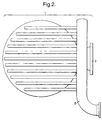
- FIG 2 is a schematic top view of the apparatus of Figure 1, showing the shape of synthesis gas collection vessel 1.
- the feed distributor system 8 for the hydrocarbonaceous feedstock is shown.
- FIG 3 is an enlargement of a reactor 5 of the apparatus of Figure 1.
- the reactor 5 comprises a catalyst bed 10 in the form of a ceramic foam and a mixer 11 which comprises a non-porous insert 12 in order to minimise the volume of the mixing zone.
- a porous shield 13 is placed to improve the velocity profile of the feed mixture, and so minimising unintentional ignition.
- the catalyst bed 10 is connected to the mixer 11 by means of catalyst mounting 14.
- the mixer 11 may be connected to the vessel wall 3 by means known in the art, for example by a bayonet connection (not shown).
- FIG 4 shows another embodiment of the apparatus according to the invention.
- the apparatus of Figure 4 comprises a synthesis gas collection vessel 1, a manifold of reactors 5 that are mounted in the synthesis gas collection vessel wall 3 in such a way that they can be replaced independently from each other, and a steam methane reforming reaction unit 16 that is vertically mounted on the synthesis gas collection vessel 1.
- the stream methane reforming reaction unit 16 comprises a plurality of reformer tubes 17 filled with catalyst (not shown). Via inlet 18, the reactants for the steam reforming reaction, i.e. methane and steam, are fed to the catalyst filled tubes 17.
- the reformer tubes 17 are open-ended.
- Hot synthesis gas produced in the catalyst beds of reactors 5 flows into the steam methane reforming reaction unit 16, there heating externally the reformer tubes 17.
- the reaction unit 16 comprises an outlet 19 via which the synthesis gas produced in both the catalyst beds of the reactors 5 and the reformer tubes 17 flows to a synthesis gas cooler (not shown).
- the synthesis gas collection vessel 1 of the apparatus of Figure 4 further comprises a man hole 20, to create the possibility of access to the inside of the vessel.
- the inner surface of the upper part of the synthesis gas collection vessel wall 3, i.e. the part wherein the reactors 5 are mounted, is lined with a water-cooled membrane 21 in order to protect the wall against hot synthesis gas.
- FIG 5 is an enlargement of a cross-section of two independently replaceable reactors 5 of the apparatus of Figure 4 through the plane B-B.
- the reactor 5 is mounted in the synthesis gas collection vessel wall 3 such that it penetrates the wall at the point where its diameter is largest. In the embodiment shown in Figure 4, the reactor has its largest diameter at the height of the mixer insert 12.
- the reactor is mounted on the vessel wall 3.
- the hydrocarbon feedstock supplied by conduit 6 enters the mixing zone through inlet hole 25.
- the temperature in the mixer is measure by means of a thermocouple 26.
- each reactor is connected to hydrocarbon feedstock distributor system 8 and oxygen-containing gas distributor 9, respectively, from which the respective reactants are distributed to the different mixers 11.
- the distributors are preferably placed between the reactors 5.
- Figure 6 is a schematic top view of the apparatus of Figure 4. Not shown are the conduits 6 and 7 that provide the reactants to the individual mixers.
- the present invention further relates to a process for the catalytic partial oxidation of a hydrocarbonaceous feedstock, which process comprises contacting each catalyst bed of the apparatus according to the invention with a feed mixture comprising a hydrocarbonaceous feedstock and an oxygen-containing gas in amounts giving an oxygen-to-carbon ratio in the range of from 0.3 to 0.8, at a pressure in the range of from 2 to 150 bara, a temperature in the range of from 750 to 1400 °C and a gas space velocity in the range of from 20,000 to 100,000,000 Nl/kg/h.
- Reference herein to temperature is to the temperature of the gas leaving the catalyst bed.
- the hydrocarbonaceous feedstock is in the gaseous phase when contacting the catalyst bed.
- the feedstock may contain compounds that are liquid and/or compounds that are gaseous under standard conditions of temperature and pressure (i.e. at 0 °C and 1 atm.).
- the process is particularly suitable for the partial oxidation of methane, natural gas, associated gas or other sources of light hydrocarbons.
- light hydrocarbons is a reference to hydrocarbons having from 1 to 5 carbon atoms.
- the process may be advantageously applied in the conversion of gas from naturally occurring reserves of methane which contain substantial amounts of carbon dioxide.
- the feed preferably comprises methane in an amount of at least 50% by volume, more preferably at least 70% by volume, especially at least 80% by volume.
- the process is also suitable for the conversion of feedstocks being gaseous when contacting the catalyst bed during operation, but being liquid under standard conditions of temperature and pressure.
- these feedstocks have an average carbon number of at least 6 and contain up to 25 carbon atoms in their molecules.
- Examples of such feedstocks are hydrocarbon feedstocks boiling in the range of from 50 °C to 500 °C, preferably in the range of from 60 °C to 350 °C.
- the process is particular suitable for the partial oxidation of liquid hydrocarbon feedstocks, such as naphtha feedstocks boiling between 35 °C and 150 °C, kerosene feedstocks boiling between 150 °C and 200 °C or synthetic gas oil feedstocks boiling between 200 °C and 500 °C, in particular between 200 °C and 300 °C.
- liquid hydrocarbon feedstocks such as naphtha feedstocks boiling between 35 °C and 150 °C, kerosene feedstocks boiling between 150 °C and 200 °C or synthetic gas oil feedstocks boiling between 200 °C and 500 °C, in particular between 200 °C and 300 °C.
- oxygenates being gaseous and/or being liquid under standard condition of temperature and pressure
- Oxygenates to be used as (part of) the feedstock in the process according to the present invention are defined as molecules containing apart from carbon and hydrogen atoms at least 1 oxygen atom which is linked to either one or two carbon atoms or to a carbon atom and a hydrogen atom.
- suitable oxygenates comprise methanol, ethanol, dimethyl ether and the like.
- mixtures of hydrocarbons and oxygenates as defined hereinbefore can be used as feedstock in the process according to the present invention.
- the hydrocarbonaceous feedstock is contacted with the catalyst bed as a mixture with an oxygen-containing gas.
- oxygen-containing gases are air, oxygen-enriched air or pure oxygen.
- the feed mixture may optionally comprise steam.
- the feed mixture may comprise carbon dioxide in a concentration of up to 60% by volume of the total feed mixture.
- the hydrocarbonaceous feedstock and the oxygen-containing gas are mixed in such amounts that the resulting feed mixture has an oxygen-to-carbon ratio in the range of from 0.3 to 0.8, preferably in the range of from 0.45 to 0.75.
- References herein to the oxygen-to-carbon ratio refer to the ratio of oxygen in the form of molecules (O 2 ) to carbon atoms present in the hydrocarbon feedstock. Oxygen-to-carbon ratios in the region of the stoichiometric ratio of 0.5, i.e. ratios in the range of from 0.45 to 0.65, are especially preferred.
- the steam-to-carbon ratio is preferably in the range of from above 0.0 to 3.0, more preferably from 0.0 to 2.0.
- the hydrocarbonaceous feedstock, the oxygen-containing gas and steam, if present, are preferably well mixed prior to being contacted with the catalyst bed.
- the feed mixture is preferably preheated prior to contacting the catalyst bed.
- the composition of the feed mixture is equal in each reactor of the apparatus according to the invention.
- the catalyst beds in the different reactors and the reactants supplied to the different reactors will be equal to each other.
- the apparatus according to the invention may be provided with different groups of reactors, comprising different catalyst beds and being supplied with different reactants or a different ratio of reactants.
- the feed mixture is preferably contacted with the catalyst bed under adiabatic conditions.
- adiabatic is a reference to reaction conditions under which substantially all heat loss and radiation from the reaction zone are prevented, with the exception of hot gas leaving the catalyst bed.
- elevated pressures that is pressures significantly above atmospheric pressure are most suitably applied in the process of the present invention.
- the process is typically operated at pressures in the range of from 2 to 150 bara.
- the process is operated at pressures in the range of from 2 to 100 bara, especially from 5 to 50 bara.
- the feed mixture is preferably contacted with the catalyst bed at a temperature in the range of from 850 to 1350 °C, more preferably of from 900 to 1300 °C.
- the feed mixture may be provided during the operation of the process at any suitable space velocity. It is an advantage of the process of the present invention that very high gas space velocities can be achieved.
- gas space velocities for the process (expressed in normal litres of gas per kilogram of catalyst per hour, wherein normal litres refers to litres under STP conditions, i.e. 0 °C and 1 atm.) are in the range of from 20,000 to 100,000,000 Nl/kg/h, more preferably in the range of from 50,000 to 50,000,000 Nl/kg/h.
- Space velocities in the range of from 500,000 to 30,000,000 Nl/kg/h are particularly suitable for use in the process.
Landscapes
- Chemical & Material Sciences (AREA)
- Organic Chemistry (AREA)
- Chemical Kinetics & Catalysis (AREA)
- Engineering & Computer Science (AREA)
- Combustion & Propulsion (AREA)
- Health & Medical Sciences (AREA)
- General Health & Medical Sciences (AREA)
- Inorganic Chemistry (AREA)
- Physics & Mathematics (AREA)
- Fluid Mechanics (AREA)
- Hydrogen, Water And Hydrids (AREA)
Priority Applications (1)
| Application Number | Priority Date | Filing Date | Title |
|---|---|---|---|
| EP00201138A EP1043271A1 (de) | 1999-03-30 | 2000-03-29 | Vorrichtung zur Teiloxidation von Kohlenwasserstoffen |
Applications Claiming Priority (3)
| Application Number | Priority Date | Filing Date | Title |
|---|---|---|---|
| EP99302490 | 1999-03-30 | ||
| EP99302490 | 1999-03-30 | ||
| EP00201138A EP1043271A1 (de) | 1999-03-30 | 2000-03-29 | Vorrichtung zur Teiloxidation von Kohlenwasserstoffen |
Publications (1)
| Publication Number | Publication Date |
|---|---|
| EP1043271A1 true EP1043271A1 (de) | 2000-10-11 |
Family
ID=26072056
Family Applications (1)
| Application Number | Title | Priority Date | Filing Date |
|---|---|---|---|
| EP00201138A Withdrawn EP1043271A1 (de) | 1999-03-30 | 2000-03-29 | Vorrichtung zur Teiloxidation von Kohlenwasserstoffen |
Country Status (1)
| Country | Link |
|---|---|
| EP (1) | EP1043271A1 (de) |
Cited By (3)
| Publication number | Priority date | Publication date | Assignee | Title |
|---|---|---|---|---|
| WO2004044095A2 (en) * | 2002-11-13 | 2004-05-27 | Regents Of The University Of Minnesota | Catalytic partial oxidation of hydrocarbons |
| US7255848B2 (en) | 2002-10-01 | 2007-08-14 | Regents Of The Univeristy Of Minnesota | Production of hydrogen from alcohols |
| US7683232B2 (en) | 2004-05-25 | 2010-03-23 | Regents Of The University Of Minnesota | Production of olefins having a functional group |
Citations (6)
| Publication number | Priority date | Publication date | Assignee | Title |
|---|---|---|---|---|
| EP0303439A2 (de) * | 1987-08-14 | 1989-02-15 | DAVY McKEE CORPORATION | Gasmischer und -verteiler für einen Reaktor |
| EP0442164A1 (de) * | 1990-01-10 | 1991-08-21 | Shell Internationale Researchmaatschappij B.V. | Festbettreaktor |
| WO1997037929A1 (en) * | 1996-04-11 | 1997-10-16 | Snamprogetti S.P.A. | Equipment for partial oxidation reactions |
| WO1998005423A1 (en) * | 1996-08-05 | 1998-02-12 | Shell Internationale Research Maatschappij B.V. | Catalyst support and process using the same |
| WO1998030322A1 (en) * | 1997-01-07 | 1998-07-16 | Shell Internationale Research Maatschappij B.V. | Fluid mixer and process using the same |
| WO1998049095A1 (en) * | 1997-04-25 | 1998-11-05 | Exxon Research And Engineering Company | Distributed injection catalytic partial oxidation process and apparatus for producing synthesis gas |
-
2000
- 2000-03-29 EP EP00201138A patent/EP1043271A1/de not_active Withdrawn
Patent Citations (6)
| Publication number | Priority date | Publication date | Assignee | Title |
|---|---|---|---|---|
| EP0303439A2 (de) * | 1987-08-14 | 1989-02-15 | DAVY McKEE CORPORATION | Gasmischer und -verteiler für einen Reaktor |
| EP0442164A1 (de) * | 1990-01-10 | 1991-08-21 | Shell Internationale Researchmaatschappij B.V. | Festbettreaktor |
| WO1997037929A1 (en) * | 1996-04-11 | 1997-10-16 | Snamprogetti S.P.A. | Equipment for partial oxidation reactions |
| WO1998005423A1 (en) * | 1996-08-05 | 1998-02-12 | Shell Internationale Research Maatschappij B.V. | Catalyst support and process using the same |
| WO1998030322A1 (en) * | 1997-01-07 | 1998-07-16 | Shell Internationale Research Maatschappij B.V. | Fluid mixer and process using the same |
| WO1998049095A1 (en) * | 1997-04-25 | 1998-11-05 | Exxon Research And Engineering Company | Distributed injection catalytic partial oxidation process and apparatus for producing synthesis gas |
Cited By (6)
| Publication number | Priority date | Publication date | Assignee | Title |
|---|---|---|---|---|
| US7255848B2 (en) | 2002-10-01 | 2007-08-14 | Regents Of The Univeristy Of Minnesota | Production of hydrogen from alcohols |
| WO2004044095A2 (en) * | 2002-11-13 | 2004-05-27 | Regents Of The University Of Minnesota | Catalytic partial oxidation of hydrocarbons |
| WO2004044095A3 (en) * | 2002-11-13 | 2004-07-01 | Univ Minnesota | Catalytic partial oxidation of hydrocarbons |
| US7262334B2 (en) | 2002-11-13 | 2007-08-28 | Regents Of The University Of Minnesota | Catalytic partial oxidation of hydrocarbons |
| US7534372B2 (en) | 2002-11-13 | 2009-05-19 | Regents Of The University Of Minnesota | Catalytic partial oxidation of hydrocarbons |
| US7683232B2 (en) | 2004-05-25 | 2010-03-23 | Regents Of The University Of Minnesota | Production of olefins having a functional group |
Similar Documents
| Publication | Publication Date | Title |
|---|---|---|
| CA2383833C (en) | Mixing device | |
| US7255840B2 (en) | Autothermal reactor and method for production of synthesis gas | |
| EP0303439B1 (de) | Gasmischer und -verteiler für einen Reaktor | |
| US7261751B2 (en) | Synthesis gas process comprising partial oxidation using controlled and optimized temperature profile | |
| AU610219B2 (en) | Production of synthesis gas from hydrocarbonaceous feedstock | |
| US20080028680A1 (en) | Process to Prepare Synthesis Gas | |
| US6887456B2 (en) | Catalyst system for enhanced flow syngas production | |
| US4758375A (en) | Conversion process | |
| US7416571B2 (en) | Compact mixer for the mixing of gaseous hydrocarbon and gaseous oxidants | |
| US6790431B2 (en) | Reactor for temperature moderation | |
| CA2582999C (en) | Reforming apparatus and method for syngas generation | |
| US7105107B2 (en) | Use of nonmicroporous support for syngas catalyst | |
| US10941088B1 (en) | Method and reactor for oxidative coupling of methane | |
| AU2009296206A1 (en) | Combined synthesis gas generator | |
| EP1043271A1 (de) | Vorrichtung zur Teiloxidation von Kohlenwasserstoffen | |
| WO2012112065A1 (ru) | Способ и устройство для получения синтез - газа | |
| US7008597B1 (en) | Catalytic reactor | |
| US7491380B2 (en) | Catalytic reactor | |
| EP1307281B1 (de) | Strömungsverteiler |
Legal Events
| Date | Code | Title | Description |
|---|---|---|---|
| PUAI | Public reference made under article 153(3) epc to a published international application that has entered the european phase |
Free format text: ORIGINAL CODE: 0009012 |
|
| AK | Designated contracting states |
Kind code of ref document: A1 Designated state(s): AT BE CH CY DE DK ES FI FR GB GR IE IT LI LU MC NL PT SE |
|
| AX | Request for extension of the european patent |
Free format text: AL;LT;LV;MK;RO;SI |
|
| AKX | Designation fees paid | ||
| STAA | Information on the status of an ep patent application or granted ep patent |
Free format text: STATUS: THE APPLICATION IS DEEMED TO BE WITHDRAWN |
|
| 18D | Application deemed to be withdrawn |
Effective date: 20010412 |
|
| REG | Reference to a national code |
Ref country code: DE Ref legal event code: 8566 |