EP1043191A1 - Back monitoring apparatus for vehicle - Google Patents
Back monitoring apparatus for vehicle Download PDFInfo
- Publication number
- EP1043191A1 EP1043191A1 EP00105731A EP00105731A EP1043191A1 EP 1043191 A1 EP1043191 A1 EP 1043191A1 EP 00105731 A EP00105731 A EP 00105731A EP 00105731 A EP00105731 A EP 00105731A EP 1043191 A1 EP1043191 A1 EP 1043191A1
- Authority
- EP
- European Patent Office
- Prior art keywords
- vehicle
- predicted path
- cornering portion
- loci
- monitoring apparatus
- Prior art date
- Legal status (The legal status is an assumption and is not a legal conclusion. Google has not performed a legal analysis and makes no representation as to the accuracy of the status listed.)
- Granted
Links
- 238000012544 monitoring process Methods 0.000 title claims abstract description 29
- 238000000034 method Methods 0.000 claims abstract description 5
- 238000012790 confirmation Methods 0.000 abstract description 3
- 238000010586 diagram Methods 0.000 description 10
- 230000003287 optical effect Effects 0.000 description 3
- 230000005540 biological transmission Effects 0.000 description 2
- 238000006243 chemical reaction Methods 0.000 description 2
- 239000013256 coordination polymer Substances 0.000 description 2
- 241000380131 Ammophila arenaria Species 0.000 description 1
- 230000004075 alteration Effects 0.000 description 1
- 239000003086 colorant Substances 0.000 description 1
Images


Classifications
-
- B—PERFORMING OPERATIONS; TRANSPORTING
- B60—VEHICLES IN GENERAL
- B60R—VEHICLES, VEHICLE FITTINGS, OR VEHICLE PARTS, NOT OTHERWISE PROVIDED FOR
- B60R1/00—Optical viewing arrangements; Real-time viewing arrangements for drivers or passengers using optical image capturing systems, e.g. cameras or video systems specially adapted for use in or on vehicles
- B60R1/20—Real-time viewing arrangements for drivers or passengers using optical image capturing systems, e.g. cameras or video systems specially adapted for use in or on vehicles
- B60R1/22—Real-time viewing arrangements for drivers or passengers using optical image capturing systems, e.g. cameras or video systems specially adapted for use in or on vehicles for viewing an area outside the vehicle, e.g. the exterior of the vehicle
- B60R1/23—Real-time viewing arrangements for drivers or passengers using optical image capturing systems, e.g. cameras or video systems specially adapted for use in or on vehicles for viewing an area outside the vehicle, e.g. the exterior of the vehicle with a predetermined field of view
- B60R1/26—Real-time viewing arrangements for drivers or passengers using optical image capturing systems, e.g. cameras or video systems specially adapted for use in or on vehicles for viewing an area outside the vehicle, e.g. the exterior of the vehicle with a predetermined field of view to the rear of the vehicle
-
- B—PERFORMING OPERATIONS; TRANSPORTING
- B60—VEHICLES IN GENERAL
- B60R—VEHICLES, VEHICLE FITTINGS, OR VEHICLE PARTS, NOT OTHERWISE PROVIDED FOR
- B60R2300/00—Details of viewing arrangements using cameras and displays, specially adapted for use in a vehicle
- B60R2300/30—Details of viewing arrangements using cameras and displays, specially adapted for use in a vehicle characterised by the type of image processing
- B60R2300/302—Details of viewing arrangements using cameras and displays, specially adapted for use in a vehicle characterised by the type of image processing combining image information with GPS information or vehicle data, e.g. vehicle speed, gyro, steering angle data
-
- B—PERFORMING OPERATIONS; TRANSPORTING
- B60—VEHICLES IN GENERAL
- B60R—VEHICLES, VEHICLE FITTINGS, OR VEHICLE PARTS, NOT OTHERWISE PROVIDED FOR
- B60R2300/00—Details of viewing arrangements using cameras and displays, specially adapted for use in a vehicle
- B60R2300/40—Details of viewing arrangements using cameras and displays, specially adapted for use in a vehicle characterised by the details of the power supply or the coupling to vehicle components
- B60R2300/404—Details of viewing arrangements using cameras and displays, specially adapted for use in a vehicle characterised by the details of the power supply or the coupling to vehicle components triggering from stand-by mode to operation mode
-
- B—PERFORMING OPERATIONS; TRANSPORTING
- B60—VEHICLES IN GENERAL
- B60R—VEHICLES, VEHICLE FITTINGS, OR VEHICLE PARTS, NOT OTHERWISE PROVIDED FOR
- B60R2300/00—Details of viewing arrangements using cameras and displays, specially adapted for use in a vehicle
- B60R2300/80—Details of viewing arrangements using cameras and displays, specially adapted for use in a vehicle characterised by the intended use of the viewing arrangement
- B60R2300/806—Details of viewing arrangements using cameras and displays, specially adapted for use in a vehicle characterised by the intended use of the viewing arrangement for aiding parking
-
- B—PERFORMING OPERATIONS; TRANSPORTING
- B60—VEHICLES IN GENERAL
- B60R—VEHICLES, VEHICLE FITTINGS, OR VEHICLE PARTS, NOT OTHERWISE PROVIDED FOR
- B60R2300/00—Details of viewing arrangements using cameras and displays, specially adapted for use in a vehicle
- B60R2300/80—Details of viewing arrangements using cameras and displays, specially adapted for use in a vehicle characterised by the intended use of the viewing arrangement
- B60R2300/8066—Details of viewing arrangements using cameras and displays, specially adapted for use in a vehicle characterised by the intended use of the viewing arrangement for monitoring rearward traffic
-
- B—PERFORMING OPERATIONS; TRANSPORTING
- B60—VEHICLES IN GENERAL
- B60R—VEHICLES, VEHICLE FITTINGS, OR VEHICLE PARTS, NOT OTHERWISE PROVIDED FOR
- B60R2300/00—Details of viewing arrangements using cameras and displays, specially adapted for use in a vehicle
- B60R2300/80—Details of viewing arrangements using cameras and displays, specially adapted for use in a vehicle characterised by the intended use of the viewing arrangement
- B60R2300/8086—Details of viewing arrangements using cameras and displays, specially adapted for use in a vehicle characterised by the intended use of the viewing arrangement for vehicle path indication
Definitions
- the present invention relates to a back monitoring apparatus for a vehicle, and more particularly to a back monitoring apparatus for a vehicle for displaying a predicted path of the vehicle according to a steering angle when the vehicle is backed up in such a manner that it is superposed on a back image on a monitor.
- a back monitoring apparatus for confirming the back of a vehicle has become prevalent.
- the feature of a back monitoring apparatus resides in that it permits a vehicle driver to confirm the back (environment) easily in such a manner that the blind spot of a rearview mirror is monitored by a video camera. This feature is efficient the case where the environment of a direct back corner of the vehicle is hidden from view by a cabin as in a truck.
- Some back monitor apparatus not only displays a back image for a driver, but also displays a predicted path locus of a rear wheel according to a steering angle when the vehicle is backed up which is superposed on the image on a monitor, thereby improving the operability of a driver.
- An example of these monitoring apparatus is disclosed in JPA64-14700.
- the display of the predicted path locus of the rear wheel disclosed in the above prior art permits the moving direction and vehicle width of one's own vehicle to be visually recognized at first sight. Therefore, the driver can easily back up the vehicle for parking.
- a front wheel 101a located outside of the turning turns widely unlike the path of a rear wheel 102a corresponding to it. Therefore, when the driver is plunged into the operation of driving carefully viewing only the interior of the predicted path lines of the rear wheels 102a and 102b, a front body 100a which turns more widely than the rear wheel 102a may be brought into contact with an obstacle 103.
- An object of the present invention is to provide a back monitor which can improve the safety confirmation and operation by a driver when a vehicle is backed up, by displaying a predicted path locus with excellent visibility in order to display a predicted path of the vehicle according to a steering angle when the vehicle is backed up in such a manner that it is superposed on a back image picked up by a video camera on a monitor.
- a back monitoring apparatus for a vehicle comprising:
- the predicted path direction of the vehicle and vehicle width can be known so that the back confirmation and operability by the driver can be improved.
- the minimum cornering portion of the vehicle is an inner rear wheel
- the maximum cornering portion of the vehicle is a front corner of an outer shape of the vehicle
- the predicted path locus of the vehicle includes that of an outer rear wheel.
- the predicted loci are displayed in display formats in which they are distinguishable from each other.
- the display format is composed of a line type, a display color, a line width and a combination thereof.
- the predicted path loci of both rear wheels and the maximum cornering portion are displayed in different display formats each composed of a line type, a display color, a line width and a combination thereof, a difference in the predicted path loci can be made clear and the driver can easily discern the difference.
- the predicted path locus of the maximum cornering portion can be displayed using the computed turning radius.
- FIGs. 2-10 an explanation will be given of an embodiment of the back monitoring apparatus for a vehicle according to the present invention.
- Fig. 2 is a block diagram showing an embodiment of the back-monitoring apparatus for a vehicle according to the present invention.
- the back monitoring apparatus includes a controller 1, a video camera 2 serving as an image pick-up means and a monitor 3 serving as display means.
- the controller 1 includes a steering sensor 4, a back sensor 5, a storage unit 6, a control unit 7 serving as a means for computing a predicted path locus and a signal processing unit 8.
- the video camera 2 which is attached to the outside of the vehicle, for example, supplies image data obtained by picking up the back scene of the vehicle to the controller 1.
- the monitor 3 displays a superposed image of the back image taken by the video camera 2 and supplied from the controller 1 and a predicted path locus when the vehicle is backed up which is computed by the controller 7.
- a steering sensor 4 produces a signal indicative of turning information of a vehicle according to a handling helm angle (steering angle) which varies by a handling operation when the vehicle is backed up.
- the back sensor 5 produces an ON/OFF signal for determining whether or not the vehicle is being backed up.
- the back sensor 5 is attached to e.g. a transmission mechanism (not shown) of the vehicle. When the gear position of the transmission mechanism is shifted to the back (reverse) position which is used when the vehicle is backed up, an ON signal is produced. When it is shifted to the other position than the reverse, an OFF signal is produced.
- the storage unit 6 stores parameter values required to compute the exhibition position of the predicted path locus of a vehicle on a monitor screen of the monitor 3.
- the storage unit 6 stores a display format selecting table which includes a plural kinds of lines (e.g. solid line, dotted line, etc.), a plurality of display colors (white, black, red, etc.), and a plurality of line widths).
- the storage unit 6 is a frame memory which temporarily stores image data captured from the video camera 2.
- the control section 7, which can be constructed of a microcomputer, etc., serves to compute the plotting position on the monitor screen of the monitor 3 of the predicted path locus of the vehicle according to the steering angle when the vehicle is backed up.
- the signal processing unit 8 superposes data of the plotting position thus computed on the image signal outputted from the video camera 2 and sends the resultant image to the monitor 3.
- a vehicle 100 moves to turn backward, it turns around a certain point p (center point) extended from a rear wheel shaft 102c.
- the turning radius of the vehicle is determined by the distance between the center point p and each of wheels 101a, 101b; and 102a, 102b. Therefore, the turning radii R1, R2, R3 and R4 of the predicted path loci 103a, 103b, 103c and 103d of the wheels 101a, 101b, 102a and 102b are from one another.
- the inner rear wheel 102b turns along the innermost line.
- the car body provides a minimum turning radius in the vicinity of the inner side 100b of the inner rear wheel. Further, it provides a maximum turning radius in the vicinity of the a front bumper corner 100a. Therefore, the vehicle 100 passes the back space confined by the minimum turning radius and the maximum turning radius. For this reason, the car body will not be brought into contact with an obstacle as long as the driver can monitor such a back space through the video camera.
- the present invention superposedly displays the predicted path loci 103a, 103c of the rear wheels 102a and 102b and a part of the car body providing the maximum turning radius (hereinafter referred to as a maximum cornering portion) (i.e. predicted path locus of the front corner 100a of the outer shape of the vehicle) on a back image taken from the video camera 2.
- a maximum cornering portion i.e. predicted path locus of the front corner 100a of the outer shape of the vehicle
- the driver can confirm the running direction and the presence or absence of a vehicle traveling space.
- the driver can know his monitoring rage through the exhibition of the maximum cornering portion, i.e. the predicted path locus of the front corner 100a.
- the driver may confuse these loci.
- these predicted path loci are discriminated from one another using different exhibition formats with respect to a line kind, line color, width, etc. For example, the predicted paths of the rear wheels 102a and 102b are exhibited in solid line, whereas that of the maximum cornering portion 100a is exhibited in dotted line. In this way, the driver can easily discriminate these predicted path loci from one another.
- control section 7 When the vehicle is backed up, the control section 7 receives an ON signal from the back sensor 5 representative of that the vehicle is being moved backward and also receives the signal from the steering sensor 4 representative of the turning information of the vehicle corresponding to the steering angle.
- control section 7 On the basis of the signal representative of the turning information of the vehicle according to the steering angle from the steering sensor 4 and the parameter values read from the storage unit 6, the control section 7 computes the plotting positions of the monitoring screen of the monitor 3 of the predicted path loci of the rear wheels 102a and 102b and the maximum cornering portion 100a.
- x r B tan ⁇ (leftward steering ⁇ > 0, rightward steering ⁇ ⁇ 0)
- R max
- B a distance between a front wheel shaft 101c and the rear wheel shaft 102c
- ⁇ a steering angle
- W vehicle width (distance between the outer walls of left and right tires)
- L front corner of the outer shape of the vehicle (i.e. the front bumper corner on the side of the outer rear wheel in this example) and the rear wheel shaft 102c.
- the locus computed by Equation (5) is picked up by a video camera installed at a position displaced from the center of the back of the vehicle 100 by dx in a X-direction and dy in a Y-direction in a direction of an optical axis having a lying angle of ⁇ .
- the respective points P(x, y) on the locus are converted from a spatial coordinate to a plane coordinate (pick-up plate) by Equation (7).
- the coordinate standard point of the pick-up plate 2a is an optical axis of the video camera 2.
- ⁇ x tan -1 x-dx
- Wx a horizontal view angle of the video camera 2
- Wy a vertical view angle of the video camera 2
- k a lens aberration coefficient
- f a focal distance of the video camera
- Cpx number of pixels on the pick-up plate 2a of the video camera in a horizontal direction
- Cpy number of pixels on the pick-up plate 2a of the video camera in a vertical direction
- E a distance between the back of the vehicle 100 and the rear wheel axis 102c
- h a vehicle height of the vehicle 100.
- Equation (10) The coordinate standard point on the monitor is an optical axis of the video camera 2 (see Fig. 9).
- [g x ,g y ] CG x CP x ⁇ p x , CG y CP y ⁇ p y
- CGx number of pixels on the monitor in the horizontal direction
- Cgy number of pixels on the monitor in the vertical direction.
- the predicted path loci of the vehicle rear wheels 102a and 102b according to the steering angle and that of the maximum cornering portion 100a of the car body can be displayed on the monitor 3.
- the control section 7 supplies to the signal processing section 8 the position data the predicted path loci of the vehicle rear wheels 102a and 102b according to the steering angle and that of the maximum cornering portion 100a of the car body, and display format information of the kind of line, display color or line width or any combination thereof which is read from the display format table stored in the storage unit 6.
- the signal processing unit 8 superposes the data of the respective path loci inclusive of the selected display format on the back image signal produced from the video camera 2, and send the superposed data to the monitor 3.
- the monitor 3 displays the predicted path loci superposed on the back image on the monitoring screen. For example, the predicted path loci of the vehicle rear wheels 102a and 102b are displayed in white solid line, and that of the maximum cornering portion 100a of the car body is displayed in red dotted line.
- the driver can know the space through the vehicle passes. This makes it easy to ensure the back safety and improve the operability.
- step S1 When the vehicle starts to back up (step S1), the control section 7 starts to acquire the signal according to the steering angle from the steering sensor 4 (step S2). In accordance with the turning information from the steering sensor 4, the control section 7 computes the predicted path loci of the vehicle rear wheels 102a, 102b and supplies these computed predicted path loci to the signal processing section 8 as information to be displayed in solid line (step S3).
- the signal processing section 8 superposes the predicted path loci information of the vehicle rear wheels 102a, 102b supplied from the control section 7 on the back image data produced from the video camera 2, and supplies the information thus created to the monitor 3.
- the monitor 3 displays the predicted path loci of the vehicle rear wheels 102a, 102b superposed in solid line on the back image on the monitor screen.
- the control section 7 computes the predicted path locus of the maximum cornering portion 100a and supplies the computed locus to the signal processing section 8 as information to be exhibited in dotted line (step S5).
- the signal processing section 8 superposes the predicted path locus information of the maximum cornering portion 100a supplied from the control section 7 on the back image data produced from the video camera 2, and supplies the information thus created to the monitor 3.
- the monitor 3 displays the predicted path locus of the maximum cornering portion 100a superposed in dotted line on the back image and the predicted loci of the vehicle path rear wheels 102a, 102b (step S6).
Abstract
Description
- The present invention relates to a back monitoring apparatus for a vehicle, and more particularly to a back monitoring apparatus for a vehicle for displaying a predicted path of the vehicle according to a steering angle when the vehicle is backed up in such a manner that it is superposed on a back image on a monitor.
- In recent years, a back monitoring apparatus for confirming the back of a vehicle has become prevalent. The feature of a back monitoring apparatus resides in that it permits a vehicle driver to confirm the back (environment) easily in such a manner that the blind spot of a rearview mirror is monitored by a video camera. This feature is efficient the case where the environment of a direct back corner of the vehicle is hidden from view by a cabin as in a truck. Some back monitor apparatus not only displays a back image for a driver, but also displays a predicted path locus of a rear wheel according to a steering angle when the vehicle is backed up which is superposed on the image on a monitor, thereby improving the operability of a driver. An example of these monitoring apparatus is disclosed in JPA64-14700.
- The display of the predicted path locus of the rear wheel disclosed in the above prior art permits the moving direction and vehicle width of one's own vehicle to be visually recognized at first sight. Therefore, the driver can easily back up the vehicle for parking. However, as shown in Fig. 11, in backing-up of the vehicle, when a vehicle 100 is turned clockwise rearwards, a front wheel 101a located outside of the turning turns widely unlike the path of a rear wheel 102a corresponding to it. Therefore, when the driver is plunged into the operation of driving carefully viewing only the interior of the predicted path lines of the rear wheels 102a and 102b, a front body 100a which turns more widely than the rear wheel 102a may be brought into contact with an obstacle 103.
- An object of the present invention is to provide a back monitor which can improve the safety confirmation and operation by a driver when a vehicle is backed up, by displaying a predicted path locus with excellent visibility in order to display a predicted path of the vehicle according to a steering angle when the vehicle is backed up in such a manner that it is superposed on a back image picked up by a video camera on a monitor.
- In order to attain the above object, in accordance with the present invention, there is provided a back monitoring apparatus for a vehicle comprising:
- a predicted path locus computing means for computing a predicted path locus of a vehicle corresponding to a steering angle when the vehicle is backed up;
- a signal processing means for processing the predicted path locus so as to be superposed on a back image picked up by an image pick-up means; and
- a monitoring means for displaying an image from the data
thus superposed,
wherein the predicted path locus computing means computes predicted path loci of a minimum cornering portion and a maximum cornering portion of the vehicle, - the signal processing means processes the predicted path loci of the minimum cornering portion and the maximum cornering portion so as to be superposed on data of the back image; and
- the monitoring means simultaneously displays the predicted path loci of the minimum cornering portion and the maximum cornering portion superposed the back image, which are supplied from the signal processing means.
-
- In this configuration, since the predicted path loci of the minimum cornering portion and the maximum cornering portion superposed on the back image are simultaneously displayed, the predicted path direction of the vehicle and vehicle width can be known so that the back confirmation and operability by the driver can be improved.
- Preferably, the minimum cornering portion of the vehicle is an inner rear wheel, the maximum cornering portion of the vehicle is a front corner of an outer shape of the vehicle, the predicted path locus of the vehicle includes that of an outer rear wheel.
- In this configuration, since the predicted path loci of both rear wheels and the maximum cornering portion are simultaneously displayed, a driver can discern the back-up direction and presence or absence of accessible space of the vehicle.
- Preferably, the predicted loci are displayed in display formats in which they are distinguishable from each other.
- In this configuration, since the predicted path loci of both rear wheels and the maximum cornering portion which are simultaneously displayed can be recognized individually according to their different display formats, they can be displayed with good visibility so that the predicted path loci of the rear wheels can be distinguishable from the maximum cornering portion.
- Preferably, the display format is composed of a line type, a display color, a line width and a combination thereof. In this configuration, since the predicted path loci of both rear wheels and the maximum cornering portion are displayed in different display formats each composed of a line type, a display color, a line width and a combination thereof, a difference in the predicted path loci can be made clear and the driver can easily discern the difference.
- Preferably, the predicted path locus of the maximum cornering portion has a turning radius computed from
- In this configuration, the predicted path locus of the maximum cornering portion can be displayed using the computed turning radius.
- The above and other objects and features of the present invention will be more apparent from the following description taken in conjunction with the accompanying drawings.
-
- Fig. 1 is a block diagram of a basic arrangement of the back monitoring apparatus for a vehicle according to the present invention;
- Fig. 2 is a block diagram of an embodiment of the back monitoring apparatus for a vehicle according to the present invention;
- Fig. 3 is a schematic diagram for explaining the turning manner of the front and rear wheels and their turning radii when a vehicle is backed up;
- Fig. 4 is a schematic diagram for explaining a method of computing predicted path loci;
- Figs. 5A and 5B are schematic plan and side views for explaining the state where a video camera is attached, respectively;
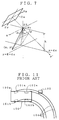
- Figs. 6 and 7 are schematic diagrams for explaining coordinate conversion from a spatial coordinate to an image pick-up plate, respectively;
- Fig. 8 is a schematic diagram for explaining the coordinate standard point on an image pick-up plate of a video camera;
- Fig. 9 is a schematic diagram for explaining the standard point of a monitor screen;
- Fig. 10 is a flowchart showing the operation in the block diagram of Fig. 2; and
- Fig. 11 is a schematic diagram for explaining the predicted path locus of a conventional back monitoring apparatus for a vehicle.
-
- Now referring to Figs. 2-10, an explanation will be given of an embodiment of the back monitoring apparatus for a vehicle according to the present invention.
- Fig. 2 is a block diagram showing an embodiment of the back-monitoring apparatus for a vehicle according to the present invention. In Fig. 2, the back monitoring apparatus includes a controller 1, a video camera 2 serving as an image pick-up means and a monitor 3 serving as display means. The controller 1 includes a steering sensor 4, a back sensor 5, a storage unit 6, a control unit 7 serving as a means for computing a predicted path locus and a signal processing unit 8. The video camera 2, which is attached to the outside of the vehicle, for example, supplies image data obtained by picking up the back scene of the vehicle to the controller 1. The monitor 3 displays a superposed image of the back image taken by the video camera 2 and supplied from the controller 1 and a predicted path locus when the vehicle is backed up which is computed by the controller 7.
- In the controller 1, a steering sensor 4 produces a signal indicative of turning information of a vehicle according to a handling helm angle (steering angle) which varies by a handling operation when the vehicle is backed up. The back sensor 5 produces an ON/OFF signal for determining whether or not the vehicle is being backed up. The back sensor 5 is attached to e.g. a transmission mechanism (not shown) of the vehicle. When the gear position of the transmission mechanism is shifted to the back (reverse) position which is used when the vehicle is backed up, an ON signal is produced. When it is shifted to the other position than the reverse, an OFF signal is produced.
- The storage unit 6 stores parameter values required to compute the exhibition position of the predicted path locus of a vehicle on a monitor screen of the monitor 3. The storage unit 6 stores a display format selecting table which includes a plural kinds of lines (e.g. solid line, dotted line, etc.), a plurality of display colors (white, black, red, etc.), and a plurality of line widths). The storage unit 6 is a frame memory which temporarily stores image data captured from the video camera 2.
- The control section 7, which can be constructed of a microcomputer, etc., serves to compute the plotting position on the monitor screen of the monitor 3 of the predicted path locus of the vehicle according to the steering angle when the vehicle is backed up. The signal processing unit 8 superposes data of the plotting position thus computed on the image signal outputted from the video camera 2 and sends the resultant image to the monitor 3.
- Referring to Fig. 3, an explanation will be given of the summary of the present invention.
- As shown in Fig. 3, during a low speed running (slippage of tires is negligible), when a vehicle 100 moves to turn backward, it turns around a certain point p (center point) extended from a rear wheel shaft 102c. In this case, the turning radius of the vehicle is determined by the distance between the center point p and each of wheels 101a, 101b; and 102a, 102b. Therefore, the turning radii R1, R2, R3 and R4 of the predicted path loci 103a, 103b, 103c and 103d of the wheels 101a, 101b, 102a and 102b are from one another. The inner rear wheel 102b turns along the innermost line. Likewise, the car body provides a minimum turning radius in the vicinity of the inner side 100b of the inner rear wheel. Further, it provides a maximum turning radius in the vicinity of the a front bumper corner 100a. Therefore, the vehicle 100 passes the back space confined by the minimum turning radius and the maximum turning radius. For this reason, the car body will not be brought into contact with an obstacle as long as the driver can monitor such a back space through the video camera.
- In view of such a fact, the present invention superposedly displays the predicted path loci 103a, 103c of the rear wheels 102a and 102b and a part of the car body providing the maximum turning radius (hereinafter referred to as a maximum cornering portion) (i.e. predicted path locus of the front corner 100a of the outer shape of the vehicle) on a back image taken from the video camera 2. Thus, the driver can confirm the running direction and the presence or absence of a vehicle traveling space. In addition, the driver can know his monitoring rage through the exhibition of the maximum cornering portion, i.e. the predicted path locus of the front corner 100a.
- In this case, if the predicted path loci of the rear wheels and the maximum cornering portion are exhibited in the same line, the driver may confuse these loci. Taking this into consideration, in accordance with the present invention, these predicted path loci are discriminated from one another using different exhibition formats with respect to a line kind, line color, width, etc. For example, the predicted paths of the rear wheels 102a and 102b are exhibited in solid line, whereas that of the maximum cornering portion 100a is exhibited in dotted line. In this way, the driver can easily discriminate these predicted path loci from one another.
- A detailed explanation will be given of the operation of the present invention.
- When the vehicle is backed up, the control section 7 receives an ON signal from the back sensor 5 representative of that the vehicle is being moved backward and also receives the signal from the steering sensor 4 representative of the turning information of the vehicle corresponding to the steering angle.
- On the basis of the signal representative of the turning information of the vehicle according to the steering angle from the steering sensor 4 and the parameter values read from the storage unit 6, the control section 7 computes the plotting positions of the monitoring screen of the monitor 3 of the predicted path loci of the rear wheels 102a and 102b and the maximum cornering portion 100a.
- An explanation will be given of a method of computing the plotting positions of the predicted path loci.
- As shown in Fig. 4, it is assumed that the vehicle 100 corners around a point P (Xr, 0) on an X-Y coordinate with an origin of the mid point of the rear wheel shaft 102c. Further, it is assumed that the turning radius of the inner rear wheel 102b is Rin, that of the outer rear wheel 102a is Rout, and that of the maximum cornering portion of the vehicle is Rmax. Incidentally, these turning radii can be computed using equations representative of the relationship between the steering angle and the turning radii which have been acquired experimentally. By replacing the vehicle by a tricycle, the turning radii R1n, Rout and Rmax can be approximated as represented by Equations (1), (2), (3) and (4).
- The locus coordinate of the vehicle which corners with the turning radius R around the point P (Xr, 0) can be obtained from Equation (5)
- Now, as shown in Figs. 5A and 5B, it is assumed that the locus computed by Equation (5) is picked up by a video camera installed at a position displaced from the center of the back of the vehicle 100 by dx in a X-direction and dy in a Y-direction in a direction of an optical axis having a lying angle of . In this case, as shown in Figs. 6 and 7, the respective points P(x, y) on the locus are converted from a spatial coordinate to a plane coordinate (pick-up plate) by Equation (7). The coordinate standard point of the pick-up plate 2a is an optical axis of the video camera 2.

- Further, coordinate conversion is made from the image pick-up plate 2a to the monitor 3. Therefore, the points of the locus are displayed on the coordinate computed by Equation (10). The coordinate standard point on the monitor is an optical axis of the video camera 2 (see Fig. 9).
- Thus, on the basis of the coordinates of the locus points computed from Equations (1) - (10), the predicted path loci of the vehicle rear wheels 102a and 102b according to the steering angle and that of the maximum cornering portion 100a of the car body can be displayed on the monitor 3.
- The control section 7 supplies to the signal processing section 8 the position data the predicted path loci of the vehicle rear wheels 102a and 102b according to the steering angle and that of the maximum cornering portion 100a of the car body, and display format information of the kind of line, display color or line width or any combination thereof which is read from the display format table stored in the storage unit 6. The signal processing unit 8 superposes the data of the respective path loci inclusive of the selected display format on the back image signal produced from the video camera 2, and send the superposed data to the monitor 3. The monitor 3 displays the predicted path loci superposed on the back image on the monitoring screen. For example, the predicted path loci of the vehicle rear wheels 102a and 102b are displayed in white solid line, and that of the maximum cornering portion 100a of the car body is displayed in red dotted line.
- Therefore, by confirming the predicted path loci of the vehicle rear wheels 102a, 102b and the maximum cornering portion 100a, the driver can know the space through the vehicle passes. This makes it easy to ensure the back safety and improve the operability.
- Referring to the flowchart shown in Fig. 10, an explanation will be given of the above operation.
- When the vehicle starts to back up (step S1), the control section 7 starts to acquire the signal according to the steering angle from the steering sensor 4 (step S2). In accordance with the turning information from the steering sensor 4, the control section 7 computes the predicted path loci of the vehicle rear wheels 102a, 102b and supplies these computed predicted path loci to the signal processing section 8 as information to be displayed in solid line (step S3).
- The signal processing section 8 superposes the predicted path loci information of the vehicle rear wheels 102a, 102b supplied from the control section 7 on the back image data produced from the video camera 2, and supplies the information thus created to the monitor 3. The monitor 3 displays the predicted path loci of the vehicle rear wheels 102a, 102b superposed in solid line on the back image on the monitor screen. Next, the control section 7 computes the predicted path locus of the maximum cornering portion 100a and supplies the computed locus to the signal processing section 8 as information to be exhibited in dotted line (step S5).
- The signal processing section 8 superposes the predicted path locus information of the maximum cornering portion 100a supplied from the control section 7 on the back image data produced from the video camera 2, and supplies the information thus created to the monitor 3. The monitor 3 displays the predicted path locus of the maximum cornering portion 100a superposed in dotted line on the back image and the predicted loci of the vehicle path rear wheels 102a, 102b (step S6).
Claims (7)
- A back monitoring apparatus for a vehicle comprising:a predicted path locus computing means for computing a predicted path locus of a vehicle corresponding to a steering angle when the vehicle is backed up;a signal processing means for processing the predicted path locus so as to be superposed on a back image picked up by an image pick-up means; anda monitoring means for displaying an image from the data thus superposed,
wherein said predicted path locus computing means computes predicted path loci of a minimum cornering portion and a maximum cornering portion of the vehicle,said signal processing means processes said predicted path loci of the minimum cornering portion and the maximum cornering portion so as to be superposed on said back image; andsaid monitoring means simultaneously displays said predicted path loci of the minimum cornering portion and the maximum cornering portion superposed said back image, which are supplied from said signal processing means . - A back monitoring apparatus according to claim 1, wherein said minimum cornering portion of the vehicle is an inner rear wheel, said maximum cornering portion of the vehicle is a front corner of an outer shape of the vehicle, and the predicted path locus of the vehicle includes that of an outer rear wheel.
- A back monitoring apparatus according to claim 1, wherein said predicted loci are displayed in display formats in which they are distinguishable from each other.
- A back monitoring apparatus according to claim 2, wherein said predicted loci are displayed in display formats in which they are distinguishable from each other.
- A back monitoring apparatus according to claim 3, wherein each said display formats is composed of a line type a display color, a line width and a combination thereof.
- A back monitoring apparatus according to claim 4, wherein each said display formats is composed of a line type a display color, a line width and a combination thereof.
- A back monitoring apparatus according to claim 2, wherein said predicted path locus of the maximum cornering portion has a turning radius computed from
Applications Claiming Priority (2)
| Application Number | Priority Date | Filing Date | Title |
|---|---|---|---|
| JP7585699 | 1999-03-19 | ||
| JP7585699 | 1999-03-19 |
Publications (2)
| Publication Number | Publication Date |
|---|---|
| EP1043191A1 true EP1043191A1 (en) | 2000-10-11 |
| EP1043191B1 EP1043191B1 (en) | 2003-07-30 |
Family
ID=13588304
Family Applications (1)
| Application Number | Title | Priority Date | Filing Date |
|---|---|---|---|
| EP00105731A Expired - Lifetime EP1043191B1 (en) | 1999-03-19 | 2000-03-17 | Back monitoring apparatus for vehicle |
Country Status (3)
| Country | Link |
|---|---|
| US (1) | US6463363B1 (en) |
| EP (1) | EP1043191B1 (en) |
| DE (1) | DE60004121T2 (en) |
Cited By (1)
| Publication number | Priority date | Publication date | Assignee | Title |
|---|---|---|---|---|
| US6564130B2 (en) * | 1999-12-24 | 2003-05-13 | Kabushiki Kaisha Toyoda Jidoshokki Seisakusho | Steering assist apparatus |
Families Citing this family (16)
| Publication number | Priority date | Publication date | Assignee | Title |
|---|---|---|---|---|
| US7983817B2 (en) * | 1995-06-07 | 2011-07-19 | Automotive Technologies Internatinoal, Inc. | Method and arrangement for obtaining information about vehicle occupants |
| DE60139236D1 (en) * | 2000-05-12 | 2009-08-27 | Toyota Jidoshokki Kariya Kk | HELP REVERSE A VEHICLE |
| EP1158803A3 (en) * | 2000-05-24 | 2003-12-10 | Matsushita Electric Industrial Co., Ltd. | Rendering device for generating a display image |
| EP1168248A3 (en) * | 2000-06-30 | 2003-12-10 | Matsushita Electric Industrial Co., Ltd. | Rendering device |
| JP3947375B2 (en) * | 2001-08-24 | 2007-07-18 | アイシン精機株式会社 | Parking assistance device |
| US7068289B2 (en) * | 2001-09-14 | 2006-06-27 | Honda Giken Kogyo Kabushiki Kaisha | Rearview monitoring apparatus for vehicle |
| JP4427953B2 (en) * | 2003-01-29 | 2010-03-10 | 株式会社豊田自動織機 | Parking assistance device |
| JP3938559B2 (en) * | 2003-08-28 | 2007-06-27 | アイシン精機株式会社 | Vehicle reverse support device |
| JP4852919B2 (en) * | 2005-07-25 | 2012-01-11 | アイシン・エィ・ダブリュ株式会社 | Vehicle ride control system and vehicle ride control method |
| JP5018149B2 (en) * | 2006-04-26 | 2012-09-05 | 日産自動車株式会社 | Driver feeling adjustment device |
| DE102007049821A1 (en) * | 2007-10-16 | 2009-04-23 | Daimler Ag | Method for calibrating an arrangement with at least one omnidirectional camera and an optical display unit |
| WO2009093371A1 (en) * | 2008-01-22 | 2009-07-30 | Sharp Kabushiki Kaisha | Display system, display control device, image display device |
| JP5035321B2 (en) | 2009-11-02 | 2012-09-26 | 株式会社デンソー | Vehicle periphery display control device and program for vehicle periphery display control device |
| US9598106B2 (en) | 2011-08-12 | 2017-03-21 | Toyota Jidosha Kabushiki Kaisha | Parking assistance device |
| KR20130037274A (en) * | 2011-10-06 | 2013-04-16 | 엘지이노텍 주식회사 | An apparatus and method for assisting parking using the multi-view cameras |
| WO2015076830A1 (en) | 2013-11-22 | 2015-05-28 | General Electric Company | Fatty acid biodispersant and methods of use |
Family Cites Families (7)
| Publication number | Priority date | Publication date | Assignee | Title |
|---|---|---|---|---|
| JPS6080953A (en) | 1983-10-12 | 1985-05-08 | Niles Parts Co Ltd | Rear monitoring device for car having distance measuring marker |
| JPS6414700A (en) | 1987-07-08 | 1989-01-18 | Aisin Aw Co | Device for displaying prospective track of vehicle |
| JP2901112B2 (en) * | 1991-09-19 | 1999-06-07 | 矢崎総業株式会社 | Vehicle periphery monitoring device |
| US5670935A (en) * | 1993-02-26 | 1997-09-23 | Donnelly Corporation | Rearview vision system for vehicle including panoramic view |
| GB9317983D0 (en) * | 1993-08-28 | 1993-10-13 | Lucas Ind Plc | A driver assistance system for a vehicle |
| JPH10147178A (en) | 1996-11-18 | 1998-06-02 | Dx Antenna Co Ltd | Rear monitoring device for vehicle |
| JP3787218B2 (en) | 1997-05-14 | 2006-06-21 | クラリオン株式会社 | Vehicle rear monitoring device |
-
2000
- 2000-03-17 US US09/527,249 patent/US6463363B1/en not_active Expired - Fee Related
- 2000-03-17 EP EP00105731A patent/EP1043191B1/en not_active Expired - Lifetime
- 2000-03-17 DE DE60004121T patent/DE60004121T2/en not_active Expired - Fee Related
Non-Patent Citations (1)
| Title |
|---|
| PATENT ABSTRACTS OF JAPAN * |
Cited By (1)
| Publication number | Priority date | Publication date | Assignee | Title |
|---|---|---|---|---|
| US6564130B2 (en) * | 1999-12-24 | 2003-05-13 | Kabushiki Kaisha Toyoda Jidoshokki Seisakusho | Steering assist apparatus |
Also Published As
| Publication number | Publication date |
|---|---|
| EP1043191B1 (en) | 2003-07-30 |
| DE60004121T2 (en) | 2004-04-15 |
| DE60004121D1 (en) | 2003-09-04 |
| US6463363B1 (en) | 2002-10-08 |
Similar Documents
| Publication | Publication Date | Title |
|---|---|---|
| EP1043191B1 (en) | Back monitoring apparatus for vehicle | |
| US10000155B2 (en) | Method and device for reproducing a lateral and/or rear surrounding area of a vehicle | |
| EP1452390B1 (en) | Apparatus and method for monitoring the immediate surroundings of a vehicle | |
| US7684593B2 (en) | Driving support system and method of producing overhead view image | |
| EP1129904B1 (en) | Monitoring device of blind zones around vehicles | |
| EP1288071B1 (en) | Parking assist system | |
| US6348858B2 (en) | Method and device for surveillance of the rearward observation area of motor vehicles | |
| US7423521B2 (en) | Vehicular visual assistance system | |
| EP0825064B1 (en) | Apparatus for checking blind spots of vehicle | |
| US20090022423A1 (en) | Method for combining several images to a full image in the bird's eye view | |
| US20170232898A1 (en) | Surrounding image display apparatus for a vehicle | |
| US20030045973A1 (en) | Motor vehicle parking support unit and method thereof | |
| US20040056955A1 (en) | Monitoring device for a motor vehicle | |
| US8477191B2 (en) | On-vehicle image pickup apparatus | |
| US20060066835A1 (en) | Method for operating an electronic viewing system and vehicle comprising an electronic viewing system | |
| US8537221B2 (en) | Lane change control system | |
| US10988144B2 (en) | Driver assistance system and method for a motor vehicle for displaying an augmented reality | |
| JP4600999B2 (en) | Vehicle perimeter monitoring device | |
| JP2010006129A (en) | Vehicle rear information display and vehicle rear information display method | |
| JP2000339598A (en) | Monitor device for vehicle | |
| JP2006163756A (en) | Vehicular view supporting device | |
| JP2003087781A (en) | Vehicle peripheral environment display device | |
| JPH0385069A (en) | On-vehicle backward confirmation camera system | |
| JP2000272416A (en) | Drive support device | |
| JP7359243B1 (en) | Vehicle indirect visibility providing system and vehicle indirect visibility providing method |
Legal Events
| Date | Code | Title | Description |
|---|---|---|---|
| PUAI | Public reference made under article 153(3) epc to a published international application that has entered the european phase |
Free format text: ORIGINAL CODE: 0009012 |
|
| AK | Designated contracting states |
Kind code of ref document: A1 Designated state(s): DE FR IT |
|
| AX | Request for extension of the european patent |
Free format text: AL;LT;LV;MK;RO;SI |
|
| 17P | Request for examination filed |
Effective date: 20010410 |
|
| AKX | Designation fees paid |
Free format text: DE FR IT |
|
| GRAH | Despatch of communication of intention to grant a patent |
Free format text: ORIGINAL CODE: EPIDOS IGRA |
|
| GRAH | Despatch of communication of intention to grant a patent |
Free format text: ORIGINAL CODE: EPIDOS IGRA |
|
| GRAA | (expected) grant |
Free format text: ORIGINAL CODE: 0009210 |
|
| AK | Designated contracting states |
Designated state(s): DE FR IT |
|
| REF | Corresponds to: |
Ref document number: 60004121 Country of ref document: DE Date of ref document: 20030904 Kind code of ref document: P |
|
| ET | Fr: translation filed | ||
| PLBE | No opposition filed within time limit |
Free format text: ORIGINAL CODE: 0009261 |
|
| STAA | Information on the status of an ep patent application or granted ep patent |
Free format text: STATUS: NO OPPOSITION FILED WITHIN TIME LIMIT |
|
| 26N | No opposition filed |
Effective date: 20040504 |
|
| PGFP | Annual fee paid to national office [announced via postgrant information from national office to epo] |
Ref country code: FR Payment date: 20060308 Year of fee payment: 7 |
|
| PGFP | Annual fee paid to national office [announced via postgrant information from national office to epo] |
Ref country code: DE Payment date: 20060309 Year of fee payment: 7 |
|
| PGFP | Annual fee paid to national office [announced via postgrant information from national office to epo] |
Ref country code: IT Payment date: 20060331 Year of fee payment: 7 |
|
| REG | Reference to a national code |
Ref country code: FR Ref legal event code: ST Effective date: 20071130 |
|
| PG25 | Lapsed in a contracting state [announced via postgrant information from national office to epo] |
Ref country code: DE Free format text: LAPSE BECAUSE OF NON-PAYMENT OF DUE FEES Effective date: 20071002 |
|
| PG25 | Lapsed in a contracting state [announced via postgrant information from national office to epo] |
Ref country code: FR Free format text: LAPSE BECAUSE OF NON-PAYMENT OF DUE FEES Effective date: 20070402 |
|
| PG25 | Lapsed in a contracting state [announced via postgrant information from national office to epo] |
Ref country code: IT Free format text: LAPSE BECAUSE OF NON-PAYMENT OF DUE FEES Effective date: 20070317 |