EP1041237A1 - Method and arrangement for automatic bow adjustment of venetian blind slats - Google Patents
Method and arrangement for automatic bow adjustment of venetian blind slats Download PDFInfo
- Publication number
- EP1041237A1 EP1041237A1 EP00302767A EP00302767A EP1041237A1 EP 1041237 A1 EP1041237 A1 EP 1041237A1 EP 00302767 A EP00302767 A EP 00302767A EP 00302767 A EP00302767 A EP 00302767A EP 1041237 A1 EP1041237 A1 EP 1041237A1
- Authority
- EP
- European Patent Office
- Prior art keywords
- strip material
- deviation
- levelling
- bow
- predetermined
- Prior art date
- Legal status (The legal status is an assumption and is not a legal conclusion. Google has not performed a legal analysis and makes no representation as to the accuracy of the status listed.)
- Granted
Links
- 238000000034 method Methods 0.000 title claims abstract description 17
- 239000000463 material Substances 0.000 claims abstract description 100
- 230000003287 optical effect Effects 0.000 claims abstract description 25
- 238000005452 bending Methods 0.000 claims abstract description 10
- 230000013011 mating Effects 0.000 claims abstract description 8
- 238000005259 measurement Methods 0.000 claims description 17
- 238000011144 upstream manufacturing Methods 0.000 claims description 4
- 230000002401 inhibitory effect Effects 0.000 claims description 3
- 230000008901 benefit Effects 0.000 abstract description 3
- 230000003247 decreasing effect Effects 0.000 abstract description 3
- 238000004519 manufacturing process Methods 0.000 description 12
- 230000005540 biological transmission Effects 0.000 description 9
- 238000003860 storage Methods 0.000 description 6
- 239000003086 colorant Substances 0.000 description 4
- 238000010276 construction Methods 0.000 description 4
- 230000007246 mechanism Effects 0.000 description 3
- 230000008569 process Effects 0.000 description 3
- 230000008859 change Effects 0.000 description 2
- 238000010586 diagram Methods 0.000 description 2
- 230000036961 partial effect Effects 0.000 description 2
- 230000002441 reversible effect Effects 0.000 description 2
- 230000004308 accommodation Effects 0.000 description 1
- XAGFODPZIPBFFR-UHFFFAOYSA-N aluminium Chemical compound [Al] XAGFODPZIPBFFR-UHFFFAOYSA-N 0.000 description 1
- 229910052782 aluminium Inorganic materials 0.000 description 1
- 239000004411 aluminium Substances 0.000 description 1
- 238000005520 cutting process Methods 0.000 description 1
- 230000002349 favourable effect Effects 0.000 description 1
- 238000007689 inspection Methods 0.000 description 1
- 238000012986 modification Methods 0.000 description 1
- 230000004048 modification Effects 0.000 description 1
- 230000002035 prolonged effect Effects 0.000 description 1
- 239000002699 waste material Substances 0.000 description 1
Images


Classifications
-
- E—FIXED CONSTRUCTIONS
- E06—DOORS, WINDOWS, SHUTTERS, OR ROLLER BLINDS IN GENERAL; LADDERS
- E06B—FIXED OR MOVABLE CLOSURES FOR OPENINGS IN BUILDINGS, VEHICLES, FENCES OR LIKE ENCLOSURES IN GENERAL, e.g. DOORS, WINDOWS, BLINDS, GATES
- E06B9/00—Screening or protective devices for wall or similar openings, with or without operating or securing mechanisms; Closures of similar construction
- E06B9/24—Screens or other constructions affording protection against light, especially against sunshine; Similar screens for privacy or appearance; Slat blinds
- E06B9/26—Lamellar or like blinds, e.g. venetian blinds
- E06B9/266—Devices or accessories for making or mounting lamellar blinds or parts thereof
-
- Y—GENERAL TAGGING OF NEW TECHNOLOGICAL DEVELOPMENTS; GENERAL TAGGING OF CROSS-SECTIONAL TECHNOLOGIES SPANNING OVER SEVERAL SECTIONS OF THE IPC; TECHNICAL SUBJECTS COVERED BY FORMER USPC CROSS-REFERENCE ART COLLECTIONS [XRACs] AND DIGESTS
- Y10—TECHNICAL SUBJECTS COVERED BY FORMER USPC
- Y10T—TECHNICAL SUBJECTS COVERED BY FORMER US CLASSIFICATION
- Y10T29/00—Metal working
- Y10T29/39—Venetian blind assembling
-
- Y—GENERAL TAGGING OF NEW TECHNOLOGICAL DEVELOPMENTS; GENERAL TAGGING OF CROSS-SECTIONAL TECHNOLOGIES SPANNING OVER SEVERAL SECTIONS OF THE IPC; TECHNICAL SUBJECTS COVERED BY FORMER USPC CROSS-REFERENCE ART COLLECTIONS [XRACs] AND DIGESTS
- Y10—TECHNICAL SUBJECTS COVERED BY FORMER USPC
- Y10T—TECHNICAL SUBJECTS COVERED BY FORMER US CLASSIFICATION
- Y10T29/00—Metal working
- Y10T29/53—Means to assemble or disassemble
- Y10T29/53039—Means to assemble or disassemble with control means energized in response to activator stimulated by condition sensor
- Y10T29/53061—Responsive to work or work-related machine element
Definitions
- the present invention relates to a method and an arrangement for automatic bow adjustment for a venetian blind assembly machine.
- Strip material from which venetian blinds are made is typically supplied in rolls or coils at one end of the machine.
- the leading end of the strip of material is fed through a levelling station, where offset rollers are positioned to receive the strip material and reversibly bend the material to remove the innate bend that results from storage in a coil condition.
- the strip material passes through a forming section where mating concave and convex upper and lower form rollers to create a transverse curvature in the strip material.
- slats are punched and cut from the strip material, whereafter they are fed to a lacing station, in which the slats are fed into the gaps between the vertical cords of a venetian blind cord ladder.
- the object of the levelling station is to remove the innate bend of the strip material that results from storage in a coiled condition and to produce substantially straight longitudinal slats for the blind.
- the extent of reverse bending of the strip material in the levelling station depends on parameters such as the dimensions for the blind. Different sizes of slat width and even different colours of blinds require different degree of reverse bending. Insufficient bending or over-bending of the strip material will have the result that the slats produced from the strip material have a bow in the longitudinal direction, either provided with an "upbow" curvature or a "downbow” curvature, lying outside acceptable predetermined deviations.
- the bow adjustments have been done more or less "manually" (that is, not automatically), by trial and error.
- the basic adjustment, as well as the continuous adjustment during production, of the levelling station has been based on experience.
- adjustments have been carried out continuously by visually controlling if there is a bow of the slats lying outside the predetermined deviations and thereafter manually adjusting the levelling station for such deviations.
- the manual adjustment of the levelling station leads to a large waste of strip material, since produced slats with an unacceptable bow must be rejected and the line must be emptied of strip material.
- manually adjusting the process is inefficient and time consuming, as the production must be stopped and restarted during the adjustments.
- the manual adjustment is especially inefficient when there is a change of dimensions or colours of the slats for production of a new blind in the machine.
- a further object is to achieve a venetian blind assembly machine, which operates more efficiently and can be easily controlled to an increasing extent with respect to what is known in the art. Yet a further purpose is to achieve an economically favourable production of venetian blinds and to minimise the drawbacks of prior art processes.
- the above mentioned problem has been solved with the present invention by providing a method for automatic bow adjustment for a venetian blind assembly machine.
- the bow adjustment station comprises rollers for guiding, bending and levelling a strip material. Further, it comprises a forming section where mating concave and convex upper and lower form rollers are arranged for creating a transverse curvature in the strip material.
- it includes the steps of: providing levelling through means for offsetting in order to straighten the bow of the strip material within a predetermined deviation on a predetermined length of strip material; measuring the deviation through optical means providing a deviation signal; and adjusting the levelling by said means for offsetting through the deviation signal, if said measured deviation exceeds a predetermined deviation value, in order to keep the deviation within said predetermined deviation value.
- An advantage with the method of the present invention is that the bow adjustment is better controlled and the manual bow adjustment can be completely avoided.
- the adjustments can be accomplished with an increasing rapidity when there is a change of the dimensions and the colours of the strip material in the production.
- a further advantage with the method of the present invention is that a decreased wastage of strip material is obtained. Hence, a much more cost efficient production of venetian blinds can be achieved.
- the present invention also relates to an arrangement for automatic bow adjustment for a venetian blind assembly machine.
- the bow adjustment station comprises rollers for guiding, bending and levelling a strip material. Further, it comprises a forming section where mating concave and convex upper and lower form rollers are arranged for creating a transverse curvature in the strip material.
- it includes: means for offsetting strip material, providing levelling in order to straighten the bow of the strip material within a predetermined deviation on a predetermined length of strip material; means for optically measuring the deviation, providing a deviation signal; and means for adjusting the levelling by said means for offsetting through the deviation signal, if said measured deviation exceeds a predetermined deviation value, in order to keep the deviation within said predetermined deviation value.
- the apparatus includes a supply section 32, means for offsetting in the form of a levelling station 34, a forming section 36, an accumulator station 38, a punch and cut section 40 and a lacing section 42.
- Aluminium strip material 43 from which venetian blinds are made is typically supplied in rolls or coils 44, which are stored at the supply section 32 on a rotatable shaft 46.
- the leading end of the strip of material is fed through the levelling station 34.
- Offset rollers 48 are positioned to receive the strip material and reversibly bend the material to remove the innate bend that results from storage in a coil condition.
- the strip material passes through a forming section 36 where mating concave and convex upper and lower form rollers 50 are positioned to create a transverse curvature in the strip material.
- An upwardly extending accumulator chamber 52 is provided at the accumulator station 38 so that a length of strip material can be stored in a loop 54. This storage is required to enable subsequent processing steps of the strip material to be intermittent.
- the strip material passes between idler rollers 56 and 58 which may have a surface adapted to remove any irregularities from the surface of the strip material.
- the strip After passing through the accumulator station 38 and idler rollers 56 and 58, the strip is driven by drive wheels 60 and 62, one of which can be driven by an electric motor.
- the drive wheels 60 and 62 cause the strip material to be fed at predetermined intervals into the punch and cut section 40, where first and second punches 66 and 68 are disposed upstream and downstream from a central cutter 70.
- the cutter 70 will cut the continuous strip into individual slats 71 of the required length.
- the punches 66 or 68 are adapted to punch holes (not shown) in the slat material strip for the accommodation of lift cords in the finished blind.
- the strip material is fed by an outfeed drive roller 72 and outfeed backup roller 74 towards the lacing section 42. Longitudinal movement of the slat material automatically feeds it through a plurality of a downstreamly spaced ladder lacing stations 78. In these ladder lacing stations 78 the slat material is laced into flexible ladder supports 76 which serve to interconnect the individual slats of a blind. Downstream of the last operative lacing station 78 or combined therewith is a stop 80 against which the leading end of each slat abuts.
- a computerised control system housed in a control unit 82 may be designed automatically to accept information and process such information depending on parameters such as the required dimensions for the finished blind. It will also be appreciated that different sizes of slat width (generally 25 mm or 16 mm) and different colours of blinds require different ladder supports. Depending on the number of ladder supports the number of lacing stations 78 that will be operative will be variable for each blind under construction. Such information is also accommodated by the computerised control system.
- Figure 2a to 5d illustrate the principle construction of a means for offsetting in the form of a levelling station 100 (generally comparable to the levelling station 34 in Figure 1) and a forming section 102 (generally comparable to the forming section 36 in Figure 1) in an arrangement for automatic bow adjustment according to the present invention.
- the levelling station 100 includes at least one upper roller 104 and a confronting lower roller 106, and the forming section 102 comprises generally an upper roller 108 and a confronting lower roller 110. All rollers serve for guiding a strip material 112 (similar to the strip material 43 of Figure 1) continuously in a forward direction of the production line.
- the levelling station 100 as well as the forming section 102 may of course comprise additional rollers (not shown).
- the rollers 104, 106 of the levelling station 100 are also adapted to receive the strip material and reversibly bend the material to remove the innate bend that usually results from prolonged storage of the strip in a coiled condition.
- the object of the rollers 104, 106 is to fine-adjust the levelling of the strip material continuously, suitably without interruption of the production cycle.
- the positioning of the rollers 104, 106 is preferably adjusted automatically by an electric supply of power (not shown but conventional).
- the power supply is transmitted through a shaft 114 and a power transmission belt 116 in connection to a screw spindle mechanism or the like (not shown but conventional) for providing the vertical position of the rollers 104, 106.
- the construction of said mechanism for providing the levelling can be made in various ways well known to the person skilled in the art.
- the rollers 104, 106 can be arranged on a vertically positioned plate, which is pivotally arranged with respect to the axle of roller 108 in the forming section.
- Figures 3a to 3d illustrate schematically rollers 104 and 106 and rollers 108 and 110 arranged on a levelling plate 105.
- Figures 3c and 3d correspond to Figures 3a and 3b with added detail and roller 110 partially cut away.
- Rollers 104 and 106 are mounted rotatably on levelling plate 105 and levelling plate 105 is rotatable about the axis of roller 108.
- the strip material In the absence of rollers 104 and 106, the strip material would pass in a straight horizontal path through the apparatus as shown by the broken line P. In particular, it would be passed from a previous set of rollers or guides (not illustrated but conventional) to rollers 108 and 110. As illustrated in Figures 3a and 3b, by tilting the levelling plate 105, the rollers 104 and 106 are deflected so as to move the strip material from its otherwise straight path. Thus, by deflecting the strip material around the rollers 104 and 106 in this way, the strip material may be appropriately levelled.
- the levelling plate 105 is attached to a threaded shaft 114 by means of a pivot 114a.
- the threaded shaft 114 passes through a threaded pulley wheel 115 which is rotatable by means of transmission belt 116.
- the transmission belt 116 to rotate the pulley wheel 115, the threaded shaft 114 is caused to move up and down and rotate the levelling plate 105 about the axis of roller 108. In this way, by controlling the transmission belt 116, the levelling operation may be conducted automatically.
- the forming section 102 is schematically illustrated.
- mating concave and convex upper 108 and lower 110 form rollers are arranged for creating a transverse curvature in the strip material 112.
- the applied pressure of the rollers 108, 110 is preferably adjusted electrically by an electric supply of power (not shown but conventional).
- a shaft 118 provided with screw threads is engaged to a supporting structure (not shown but conventional).
- the shaft 118 is engaged by its thread in a threaded pulley wheel 119 which is rotated by a supply of power via a power transmission belt 120.
- the shaft is freely rotatably mounted in a member 122, suitably attached to the lower roller 110, for adjusting the applied pressure by the rollers 108, 110.
- the shaft 118 is movable in an axial and substantially vertical direction (as indicated by the arrows in fig.4).
- the member 122 can be an arm portion 124 attached at one end to the axle of the lower roller 110.
- the other end of the arm portion 124 may be in the form of a sleeve part 126 in which the lower part of the shaft 118 is internally arranged and freely axially movable.
- a spring 128 is arranged on the lower part of the shaft 118, in between the lower end 130 of the shaft and the sleeve part 126 of the arm portion 124.
- the spring 128 acts on the member 122 as a prestressing force of the lower roller 110.
- the shaft is arranged to move in an axial direction with rotation of the pulley wheel 119 and is restrained from rotation about its axis.
- the lower end 130 is movable up and down, such that the spring is compressed and relaxed and the lower roller 110 provides a increasing or decreasing pressure towards the strip material 112.
- the applied pressure by the rollers 108, 100 also contributes to reversibly bend the strip material 112, in addition to the levelling station 100. Accordingly, during production, the rollers 108, 110 are more or less fixed in a predetermined position with pressure acting on the strip material while the rollers 104, 106 of the levelling station 100 are pivoted up or down for the fine adjustment of the levelling.
- the angle with which the strip material is introduced in the nip between the rollers 108, 110 in the forming section will vary.
- the coarse adjustment of the pressure and/or levelling towards the strip material is positioned with rollers 108, 110 from the start, while the fine adjustment for the levelling of the strip material is done with rollers 104, 106 of the levelling station.
- FIGS. 5a to 5d illustrate the forming section in greater detail.
- lower roller 110 is rotatable on arm portion 124 about a pivot 124a on the levelling plate. In this way, as illustrated in Figures 5a and 5b, lower roller 110 may be pivoted towards and away from upper roller 108.
- the arm portion 124 has a sleeve part 126 through which the shaft 118 extends.
- a spring 128 is positioned around the shaft 118 and is sandwiched between the sleeve part 126 and the lower end 130 of the shaft 118.
- the spring 128 is compressed so as to create additional pressure on sleeve part 126, thereby urging roller 110 to pivot about pivot 124a and create additional pressure between the rollers 108 and 110.
- the pressure between the rollers 108 and 110 can be varied according to the strip material being used.
- the shaft 118 has a threaded portion 118a at at least one end.
- the threaded portion 118a engages with a threaded pulley wheel 119 such that rotation of the pulley wheel 119 causes shaft 118 to move up or down as illustrated in Figures 5c and 5d.
- a transmission belt 120 is provided to drive the pulley 119.
- the apparatus is able automatically to adjust the pressure provided between the upper and lower rollers 108 and 110 for forming the strip material appropriately.
- an accumulator station 140 (similar to the accumulator station 38 of Figure 1) is suitably provided for in the arrangement for automatic bow adjustment according to the present invention.
- An accumulator chamber 142 (similar to the accumulator chamber 52 of Figure 1), being upwardly extended, is provided at the accumulator station 140 so that a length of strip material 112 can be accumulated in a loop 144. This storage is required to enable subsequent processing steps of the strip material 112 to be intermittent.
- Optical means 146 is preferably arranged at the wall 148 of the accumulator chamber 142. The optical means is connected to a computerised control system via power and control cable 147.
- the optical means 146 can be a laser, ultraviolet or infrared operating means, or photoelectric sensors.
- the optical means is preferably a laser.
- levelling is provided through means for offsetting at the levelling station 100 in order to straighten the bow of the strip material within a predetermined deviation on a predetermined length of strip material.
- optical means 146 at the accumulator station, deviations are continuously measured, during the movement of the strip material, through optical means 146.
- the optical means 146 provides a deviation signal, which is registered and treated in a computer.
- the levelling by said means for offsetting 100 is adjusted through the deviation signal, if said measured deviation exceeds a predetermined deviation, in order to keep the deviation within said predetermined deviation.
- the optical means should preferably be able to measure deviations of, for example, ⁇ 0.2 mm along a certain length of the strip material, i.e. within a range between 400 mm and 1200 mm.
- the strip material 112 is in a fixed position during the measurement of the optical means 146.
- supporting means 150, 152 can be attached to the accumulator chamber 142.
- the supporting means 150, 152 are preferably attached to said accumulator chamber of said accumulator station, each on one of an upstream and downstream side of said means for optical measurement 146.
- FIG. 7 a schematic principal block diagram 400 for an embodiment of the automatic bow adjustment according to the present invention is depicted.
- An operator panel 410 and a bar code reader 415 provides a Man Machine Interface (MMI) for the venetian blind machine, i.e., means for parameter setting of the machine such as with parameters for the specific strip material 43, 112 in use through means for offsetting 34, 100, 102 in order to straighten the bow of the strip material 43, 112 within a predetermined deviation on a predetermined length of strip material.
- MMI Man Machine Interface
- a PC control system 420 for the parameter setting is governed by a kernel 430 connected to digital 440 and analogue 450 I/O interfaces, respectively, for control of means 100, 102 regarding i.a. bow adjustment via signals emanating from the means for optical measurement 146.
- Switches 442 and 444 are connected to the digital interface 440 for On/Off control of the setting of motor means M1 and M2, respectively, in a slat profiling unit 460.
- Motors M1 and M2 are preferably of the type stepper, servo or the like motors.
- the motor M1 provides a coarse adjustment transmitted via the power transmission belt 120, which is also connected to an axis (not shown) of the motor Ml, in a manner known by those skilled in the art.
- M1 is connected to an input of the I/O interface 450 through a weight indicator 470 providing a position signal, for example inputted as pressure in kilogram, for the coarse adjustment of rollers 110, 108.
- the motor M2 is connected to an axis 114 via its axis (not shown), in a manner known by those skilled in the art, via the power transmission belt 116.
- M2 provides the fine adjustment for levelling in accordance with the present invention through the axis 114 connected to the levelling station 100 in a known manner for those skilled in the art.
- Means 146 for optical measurement of deviation in bending of the strip material transmits its signals picked up to the PC control system 420 which outputs control signals to the motor M2 in accordance with the measured deviation, thus compensating the bow to be within a predetermined deviation, for example, ⁇ 0.2 mm.
- the device 480 indicated as a field regulator in Fig. 7, inputs a value for deviations to the control system 420, used to make necessary calculations and determinations for regulation via M2 etc.
- the strip accumulator unit 490 comprises a rectifier 495 for input of a trigger signal to the control system 420 for trigging the measurement period of an optical means during for example cutting of the strip material.
- said deviation signal is used as a feedback signal, thus inhibiting time periods for control measurement of said bow and unnecessary loss of strip material compared with possible feed-forward measurements by placing the optical means before station 100 and/or section 102.
- the optical means e.g. the preferred laser measurements
- the means for offsetting and in addition, possibly have means for controlling the deviation after the forming section without using a feed-back signal. If the laser measurements are made before the means for offsetting (i.e. even before the levelling station, there will be no feedback signal, but rather feed-forward measurements). However, the most preferred arrangement is still after the forming section as stated in claims 2 and 6.
Landscapes
- Engineering & Computer Science (AREA)
- Structural Engineering (AREA)
- Architecture (AREA)
- Civil Engineering (AREA)
- Blinds (AREA)
- Bending Of Plates, Rods, And Pipes (AREA)
Abstract
Description
- The present invention relates to a method and an arrangement for automatic bow adjustment for a venetian blind assembly machine.
- The production of venetian blinds of different sizes and types in venetian blind assembly machines is previously known in the art. Strip material from which venetian blinds are made is typically supplied in rolls or coils at one end of the machine. The leading end of the strip of material is fed through a levelling station, where offset rollers are positioned to receive the strip material and reversibly bend the material to remove the innate bend that results from storage in a coil condition. Subsequently, the strip material passes through a forming section where mating concave and convex upper and lower form rollers to create a transverse curvature in the strip material. Further on in the line of the assembly machine, slats are punched and cut from the strip material, whereafter they are fed to a lacing station, in which the slats are fed into the gaps between the vertical cords of a venetian blind cord ladder.
- The object of the levelling station is to remove the innate bend of the strip material that results from storage in a coiled condition and to produce substantially straight longitudinal slats for the blind. The extent of reverse bending of the strip material in the levelling station depends on parameters such as the dimensions for the blind. Different sizes of slat width and even different colours of blinds require different degree of reverse bending. Insufficient bending or over-bending of the strip material will have the result that the slats produced from the strip material have a bow in the longitudinal direction, either provided with an "upbow" curvature or a "downbow" curvature, lying outside acceptable predetermined deviations. According to the prior art production of venetian blinds, the bow adjustments have been done more or less "manually" (that is, not automatically), by trial and error. The basic adjustment, as well as the continuous adjustment during production, of the levelling station has been based on experience. During production, adjustments have been carried out continuously by visually controlling if there is a bow of the slats lying outside the predetermined deviations and thereafter manually adjusting the levelling station for such deviations.
- The manual adjustment of the levelling station leads to a large waste of strip material, since produced slats with an unacceptable bow must be rejected and the line must be emptied of strip material. In addition, manually adjusting the process is inefficient and time consuming, as the production must be stopped and restarted during the adjustments. The manual adjustment is especially inefficient when there is a change of dimensions or colours of the slats for production of a new blind in the machine.
- Therefore, it is an object of the present invention to overcome or ameliorate at least one of the disadvantages of the prior art and to achieve less wastage of the strip material. A further object is to achieve a venetian blind assembly machine, which operates more efficiently and can be easily controlled to an increasing extent with respect to what is known in the art. Yet a further purpose is to achieve an economically favourable production of venetian blinds and to minimise the drawbacks of prior art processes.
- The above mentioned problem has been solved with the present invention by providing a method for automatic bow adjustment for a venetian blind assembly machine. The bow adjustment station comprises rollers for guiding, bending and levelling a strip material. Further, it comprises a forming section where mating concave and convex upper and lower form rollers are arranged for creating a transverse curvature in the strip material. In addition it includes the steps of: providing levelling through means for offsetting in order to straighten the bow of the strip material within a predetermined deviation on a predetermined length of strip material; measuring the deviation through optical means providing a deviation signal; and adjusting the levelling by said means for offsetting through the deviation signal, if said measured deviation exceeds a predetermined deviation value, in order to keep the deviation within said predetermined deviation value.
- An advantage with the method of the present invention is that the bow adjustment is better controlled and the manual bow adjustment can be completely avoided. Thus, the adjustments can be accomplished with an increasing rapidity when there is a change of the dimensions and the colours of the strip material in the production.
- A further advantage with the method of the present invention is that a decreased wastage of strip material is obtained. Hence, a much more cost efficient production of venetian blinds can be achieved.
- In addition, the present invention also relates to an arrangement for automatic bow adjustment for a venetian blind assembly machine. The bow adjustment station comprises rollers for guiding, bending and levelling a strip material. Further, it comprises a forming section where mating concave and convex upper and lower form rollers are arranged for creating a transverse curvature in the strip material. In addition it includes: means for offsetting strip material, providing levelling in order to straighten the bow of the strip material within a predetermined deviation on a predetermined length of strip material; means for optically measuring the deviation, providing a deviation signal; and means for adjusting the levelling by said means for offsetting through the deviation signal, if said measured deviation exceeds a predetermined deviation value, in order to keep the deviation within said predetermined deviation value.
- Embodiments of the present invention are described, without restricting the scope of the present invention thereto with reference to the accompanying drawings, in which:
- Figure 1 is a schematic front elevation illustrating a prior art slat assembly apparatus and showing various processing stations.
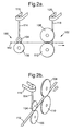
- Figure 2a shows a schematic side view of a levelling and forming station in an arrangement for automatic bow adjustment according to the present invention.
- Figure 2b illustrates schematically a partial perspective view of the levelling and forming station of fig. 2a;
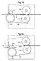
- Figures 3a to 3d illustrate a levelling and forming station according to the present invention;
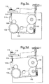
- Figure 4 illustrates schematically another partial perspective view of the levelling and forming station of fig. 2a;
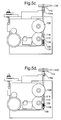
- Figures 5a to 5d illustrate a levelling and forming station according to the present invention;
- Figure 6 shows a schematic side view of an accumulator station in the arrangement for automatic bow adjustment according to the present invention;
- Figure 7 shows a principal diagram of connections for the automatic bow adjustment according to the present invention.
-
- An
apparatus 30 for assembling venetian blinds is illustrated in figure 1. The apparatus includes asupply section 32, means for offsetting in the form of alevelling station 34, a formingsection 36, anaccumulator station 38, a punch andcut section 40 and alacing section 42. -
Aluminium strip material 43 from which venetian blinds are made is typically supplied in rolls orcoils 44, which are stored at thesupply section 32 on arotatable shaft 46. The leading end of the strip of material is fed through thelevelling station 34.Offset rollers 48 are positioned to receive the strip material and reversibly bend the material to remove the innate bend that results from storage in a coil condition. - After the
levelling station 34, the strip material passes through a formingsection 36 where mating concave and convex upper andlower form rollers 50 are positioned to create a transverse curvature in the strip material. An upwardly extendingaccumulator chamber 52 is provided at theaccumulator station 38 so that a length of strip material can be stored in aloop 54. This storage is required to enable subsequent processing steps of the strip material to be intermittent. - From the
accumulator station 38, the strip material passes betweenidler rollers - After passing through the
accumulator station 38 andidler rollers drive wheels - The
drive wheels section 40, where first andsecond punches 66 and 68 are disposed upstream and downstream from acentral cutter 70. Thecutter 70 will cut the continuous strip intoindividual slats 71 of the required length. Thepunches 66 or 68 are adapted to punch holes (not shown) in the slat material strip for the accommodation of lift cords in the finished blind. - Coming from the cut and
punch section 40, the strip material is fed by an outfeeddrive roller 72 and outfeedbackup roller 74 towards thelacing section 42. Longitudinal movement of the slat material automatically feeds it through a plurality of a downstreamly spacedladder lacing stations 78. In theseladder lacing stations 78 the slat material is laced into flexible ladder supports 76 which serve to interconnect the individual slats of a blind. Downstream of the lastoperative lacing station 78 or combined therewith is astop 80 against which the leading end of each slat abuts. - A computerised control system housed in a
control unit 82 may be designed automatically to accept information and process such information depending on parameters such as the required dimensions for the finished blind. It will also be appreciated that different sizes of slat width (generally 25 mm or 16 mm) and different colours of blinds require different ladder supports. Depending on the number of ladder supports the number oflacing stations 78 that will be operative will be variable for each blind under construction. Such information is also accommodated by the computerised control system. - Figure 2a to 5d illustrate the principle construction of a means for offsetting in the form of a levelling station 100 (generally comparable to the
levelling station 34 in Figure 1) and a forming section 102 (generally comparable to the formingsection 36 in Figure 1) in an arrangement for automatic bow adjustment according to the present invention. - As can be seen from figs. 2a and 2b, the levelling
station 100 includes at least oneupper roller 104 and a confrontinglower roller 106, and the formingsection 102 comprises generally anupper roller 108 and a confrontinglower roller 110. All rollers serve for guiding a strip material 112 (similar to thestrip material 43 of Figure 1) continuously in a forward direction of the production line. However, the levellingstation 100 as well as the formingsection 102 may of course comprise additional rollers (not shown). Therollers station 100 are also adapted to receive the strip material and reversibly bend the material to remove the innate bend that usually results from prolonged storage of the strip in a coiled condition. The object of therollers rollers shaft 114 and apower transmission belt 116 in connection to a screw spindle mechanism or the like (not shown but conventional) for providing the vertical position of therollers rollers roller 108 in the forming section. - A particular embodiment of the mechanism for providing levelling is illustrated in Figures 3a to 3d. Figures 3a and 3b illustrate schematically
rollers rollers levelling plate 105. Figures 3c and 3d correspond to Figures 3a and 3b with added detail androller 110 partially cut away. -
Rollers plate 105 and levellingplate 105 is rotatable about the axis ofroller 108. - In the absence of
rollers rollers plate 105, therollers rollers - As illustrated in Figures 3c and 3d, the levelling
plate 105 is attached to a threadedshaft 114 by means of apivot 114a. The threadedshaft 114 passes through a threadedpulley wheel 115 which is rotatable by means oftransmission belt 116. Thus, by operating thetransmission belt 116 to rotate thepulley wheel 115, the threadedshaft 114 is caused to move up and down and rotate the levellingplate 105 about the axis ofroller 108. In this way, by controlling thetransmission belt 116, the levelling operation may be conducted automatically. - Turning now to fig. 4, the forming
section 102 is schematically illustrated. In the forming section, mating concave and convex upper 108 and lower 110 form rollers are arranged for creating a transverse curvature in thestrip material 112. The applied pressure of therollers shaft 118 provided with screw threads is engaged to a supporting structure (not shown but conventional). Theshaft 118 is engaged by its thread in a threadedpulley wheel 119 which is rotated by a supply of power via apower transmission belt 120. The shaft is freely rotatably mounted in amember 122, suitably attached to thelower roller 110, for adjusting the applied pressure by therollers shaft 118 is movable in an axial and substantially vertical direction (as indicated by the arrows in fig.4). Themember 122 can be anarm portion 124 attached at one end to the axle of thelower roller 110. The other end of thearm portion 124 may be in the form of asleeve part 126 in which the lower part of theshaft 118 is internally arranged and freely axially movable. Aspring 128 is arranged on the lower part of theshaft 118, in between thelower end 130 of the shaft and thesleeve part 126 of thearm portion 124. Thespring 128 acts on themember 122 as a prestressing force of thelower roller 110. The shaft is arranged to move in an axial direction with rotation of thepulley wheel 119 and is restrained from rotation about its axis. Hence, when the shaft is actuated by supply of power, thelower end 130 is movable up and down, such that the spring is compressed and relaxed and thelower roller 110 provides a increasing or decreasing pressure towards thestrip material 112. Moreover, the applied pressure by therollers strip material 112, in addition to the levellingstation 100. Accordingly, during production, therollers rollers station 100 are pivoted up or down for the fine adjustment of the levelling. Hence, by pivoting the levellingstation 100, the angle with which the strip material is introduced in the nip between therollers rollers rollers - Figures 5a to 5d illustrate the forming section in greater detail.
- As illustrated in Figures 5a and 5b,
lower roller 110 is rotatable onarm portion 124 about apivot 124a on the levelling plate. In this way, as illustrated in Figures 5a and 5b,lower roller 110 may be pivoted towards and away fromupper roller 108. - Referring to Figures 5c and 5d (in which the
roller 110 is illustrated partially cut away), it will be seen that thearm portion 124 has asleeve part 126 through which theshaft 118 extends. Aspring 128 is positioned around theshaft 118 and is sandwiched between thesleeve part 126 and thelower end 130 of theshaft 118. Thus, by moving theshaft 118 upwardly as illustrated in Figures 5c and 5d, thespring 128 is compressed so as to create additional pressure onsleeve part 126, thereby urgingroller 110 to pivot aboutpivot 124a and create additional pressure between therollers - Thus, by varying the position of the
shaft 118, the pressure between therollers - As illustrated, the
shaft 118 has a threadedportion 118a at at least one end. In particular, the threadedportion 118a engages with a threadedpulley wheel 119 such that rotation of thepulley wheel 119 causesshaft 118 to move up or down as illustrated in Figures 5c and 5d. Furthermore, atransmission belt 120 is provided to drive thepulley 119. Thus, by operating thetransmission belt 120, the apparatus is able automatically to adjust the pressure provided between the upper andlower rollers - As illustrated in Figure 6, in a subsequent stage, after the forming section, an accumulator station 140 (similar to the
accumulator station 38 of Figure 1) is suitably provided for in the arrangement for automatic bow adjustment according to the present invention. An accumulator chamber 142 (similar to theaccumulator chamber 52 of Figure 1), being upwardly extended, is provided at theaccumulator station 140 so that a length ofstrip material 112 can be accumulated in aloop 144. This storage is required to enable subsequent processing steps of thestrip material 112 to be intermittent. Optical means 146 is preferably arranged at thewall 148 of theaccumulator chamber 142. The optical means is connected to a computerised control system via power and control cable 147. The optical means 146 can be a laser, ultraviolet or infrared operating means, or photoelectric sensors. The optical means is preferably a laser. In addition, there may also be supporting means 150, 152 for guiding and fixing thestrip material 112 in theaccumulator chamber 142. Consequently, the supportingmeans control cables station 100 in order to straighten the bow of the strip material within a predetermined deviation on a predetermined length of strip material. However, by the use of the optical means 146 at the accumulator station, deviations are continuously measured, during the movement of the strip material, throughoptical means 146. The optical means 146 provides a deviation signal, which is registered and treated in a computer. The levelling by said means for offsetting 100 is adjusted through the deviation signal, if said measured deviation exceeds a predetermined deviation, in order to keep the deviation within said predetermined deviation. The optical means should preferably be able to measure deviations of, for example, ±0.2 mm along a certain length of the strip material, i.e. within a range between 400 mm and 1200 mm. - During said measuring of the
strip material 112, it is essential that the strip material is substantially straight and properly aligned. Preferably, thestrip material 112 is in a fixed position during the measurement of theoptical means 146. For the purpose of holding thestrip material 112 in position for said measuring, supportingmeans accumulator chamber 142. The supporting means 150, 152 are preferably attached to said accumulator chamber of said accumulator station, each on one of an upstream and downstream side of said means foroptical measurement 146. It is suitable to hold the strip material and to make the measurements with the optical means 146 simultaneously when a slat is lifted in the lacingstation 78, when a new blind is set-up or during acut 70 and/or punch 66, 68 operation on thestrip material strip material 112 then is shortly interrupted anyway. - As illustrated by fig. 7, a schematic principal block diagram 400 for an embodiment of the automatic bow adjustment according to the present invention is depicted. An
operator panel 410 and abar code reader 415 provides a Man Machine Interface (MMI) for the venetian blind machine, i.e., means for parameter setting of the machine such as with parameters for thespecific strip material strip material - A
PC control system 420 for the parameter setting is governed by akernel 430 connected to digital 440 and analogue 450 I/O interfaces, respectively, for control ofmeans optical measurement 146. -
Switches digital interface 440 for On/Off control of the setting of motor means M1 and M2, respectively, in aslat profiling unit 460. Motors M1 and M2 are preferably of the type stepper, servo or the like motors. - The motor M1 provides a coarse adjustment transmitted via the
power transmission belt 120, which is also connected to an axis (not shown) of the motor Ml, in a manner known by those skilled in the art. M1 is connected to an input of the I/O interface 450 through aweight indicator 470 providing a position signal, for example inputted as pressure in kilogram, for the coarse adjustment ofrollers - The motor M2 is connected to an
axis 114 via its axis (not shown), in a manner known by those skilled in the art, via thepower transmission belt 116. M2 provides the fine adjustment for levelling in accordance with the present invention through theaxis 114 connected to the levellingstation 100 in a known manner for those skilled in the art.Means 146 for optical measurement of deviation in bending of the strip material transmits its signals picked up to thePC control system 420 which outputs control signals to the motor M2 in accordance with the measured deviation, thus compensating the bow to be within a predetermined deviation, for example, ± 0.2 mm. Thedevice 480, indicated as a field regulator in Fig. 7, inputs a value for deviations to thecontrol system 420, used to make necessary calculations and determinations for regulation via M2 etc. - It is easily understood that deviations within two tenths of a mm are hard, if not impossible, to cope with using methods and arrangements presently known to a person skilled in the art to which the present invention pertains, mainly ocular inspection. But with the optical means for measurement and the method according to the present invention, such deviations are possible to op-hold, with for example a laser measurement device in coordination with other measures claimed in the attached set of claims.
- The
strip accumulator unit 490 comprises arectifier 495 for input of a trigger signal to thecontrol system 420 for trigging the measurement period of an optical means during for example cutting of the strip material. - Further, by providing the optical means after the levelling
station 100 and the formingsection 102 at theaccumulator station station 100 and/orsection 102. - It is possible to arrange the optical means, e.g. the preferred laser measurements, before the means for offsetting (and in addition, possibly have means for controlling the deviation after the forming section without using a feed-back signal). If the laser measurements are made before the means for offsetting (i.e. even before the levelling station, there will be no feedback signal, but rather feed-forward measurements). However, the most preferred arrangement is still after the forming section as stated in claims 2 and 6.
- It is thus believed that the operation and construction of the present invention will be apparent from the foregoing description. The term comprising when used in this description or the appended claims should not be construed in an exclusive or exhaustive sense but rather in an inclusive sense. Features which are not specifically described or claimed may be additionally included in the structure according to the present invention without deviating from its scope. While the method and arrangement illustrated or described has been characterized as being preferred it will be obvious that various changes and modifications may be made therein without departing from the spirit and scope of the invention as defined in the attached claims. It is particularly within the scope of the present invention that any adjusted settings of the bow adjusting means may be electronically saved for future retrieval and re-use.
Claims (8)
- A method for automatic bow adjustment for a venetian blind assembly machine, comprising a bow adjustment station comprising rollers (48; 104, 106) for guiding, bending and levelling a strip material (43; 112), and further comprising a forming section (36; 102) where mating concave and convex upper and lower form rollers (50; 108, 110) are arranged for creating a transverse curvature in the strip material, said method including the steps of:providing levelling through means for offsetting (34; 100, 102) in order to straighten the bow of the strip material (43; 112) within a predetermined deviation on a predetermined length of strip material;measuring the deviation through optical means (146) providing a deviation signal; andadjusting the levelling by said means for offsetting (34; 100, 102) through the deviation signal, if said measured deviation exceeds a predetermined deviation value, in order to keep the deviation within said predetermined deviation value.
- A method according to claim 1, wherein said optical means (146) are provided after said forming section (36; 102) on an accumulator station (38; 140) for accumulating strip material (43; 112).
- A method according to claim 2, wherein two supporting means (150, 152) are attached to an accumulator chamber (52; 142) of said accumulator station each on one of an upstream and down stream side of said optical means (146) to hold the strip material (43; 112) in a predetermined position for said measuring during a cut (70) and/or punch (66, 68) operation on the strip material.
- A method according to claims 1-3, wherein said deviation signal being a feedback signal, thus inhibiting time periods for control measurement of said bow and unnecessary loss of strip material.
- An arrangement for automatic bow adjustment for a venetian blind assembly machine, comprising bow adjustment station comprising rollers (48; 104, 106) for guiding, bending and levelling a strip material (43; 112), and further comprising a forming section (36; 102) where mating concave and convex upper and lower form rollers (50; 108, 110) are arranged for creating a transverse curvature in the strip material, said arrangement including:means (34; 100, 102) for offsetting strip material (43; 112), providing levelling in order to straighten the bow of the strip material within a predetermined deviation on a predetermined length of strip material;means (146) for optically measuring the deviation, providing a deviation signal; andmeans (114, 116) for adjusting the levelling by said means (34; 100, 102) for offsetting through the deviation signal, if said measured deviation exceeds a predetermined deviation value, in order to keep the deviation within said predetermined deviation value.
- An arrangement according to claim 5, wherein said means (146) for optical measurement are provided after said forming section on an accumulator station (38; 140) for storing strip material (43; 112).
- An arrangement according to claim 6, wherein two supporting means (150, 152) are attached to an accumulator chamber (52; 142) of said accumulator station, each on one of an upstream and downstream side of said means (146) for optical measurement, to hold the strip material (43; 112) in a predetermined position for said measuring during a cut (70) and/or punch (66, 68) operation on the strip material.
- An arrangement according to claims 5-7, wherein said means for adjusting are controlled through said deviation signal as a feedback signal, thus inhibiting time periods for control measurement of said bow and unnecessary loss of strip material.
Priority Applications (2)
| Application Number | Priority Date | Filing Date | Title |
|---|---|---|---|
| EP00302767A EP1041237B1 (en) | 1999-04-02 | 2000-03-31 | Method and arrangement for automatic bow adjustment of venetian blind slats |
| DK00302767T DK1041237T3 (en) | 1999-04-02 | 2000-03-31 | Method and device for automatic bending adjustment |
Applications Claiming Priority (3)
| Application Number | Priority Date | Filing Date | Title |
|---|---|---|---|
| EP99201013 | 1999-04-02 | ||
| EP99201013 | 1999-04-02 | ||
| EP00302767A EP1041237B1 (en) | 1999-04-02 | 2000-03-31 | Method and arrangement for automatic bow adjustment of venetian blind slats |
Publications (2)
| Publication Number | Publication Date |
|---|---|
| EP1041237A1 true EP1041237A1 (en) | 2000-10-04 |
| EP1041237B1 EP1041237B1 (en) | 2004-09-29 |
Family
ID=8240049
Family Applications (1)
| Application Number | Title | Priority Date | Filing Date |
|---|---|---|---|
| EP00302767A Expired - Lifetime EP1041237B1 (en) | 1999-04-02 | 2000-03-31 | Method and arrangement for automatic bow adjustment of venetian blind slats |
Country Status (6)
| Country | Link |
|---|---|
| US (2) | US6393884B1 (en) |
| EP (1) | EP1041237B1 (en) |
| AU (1) | AU757340B2 (en) |
| CA (1) | CA2303665A1 (en) |
| DE (1) | DE60014220T2 (en) |
| DK (1) | DK1041237T3 (en) |
Families Citing this family (6)
| Publication number | Priority date | Publication date | Assignee | Title |
|---|---|---|---|---|
| AU757340B2 (en) * | 1999-04-02 | 2003-02-20 | Hunter Douglas Industries Bv | Method and arrangement for automatic bow adjustment |
| US6679611B2 (en) | 2002-06-14 | 2004-01-20 | Lockheed Martin Corporation | Adaptive, aluminized Mylar mirror |
| CZ16464U1 (en) * | 2006-01-27 | 2006-05-03 | Zebr S. R. O. | Guiding device of endless thin-walled strip feeder magazine |
| US9266159B2 (en) | 2011-08-02 | 2016-02-23 | Chad Wooters | Venetian blind repair tool |
| CN109047338B (en) * | 2018-06-29 | 2020-03-27 | 首钢京唐钢铁联合有限责任公司 | Micron-sized cold rolling system space precision control method |
| CN114406041B (en) * | 2021-12-24 | 2024-07-05 | 宜昌清江电气有限公司 | Automatic detection leveling system and method applicable to bus bars of high-medium-low-voltage electrical cabinets |
Citations (1)
| Publication number | Priority date | Publication date | Assignee | Title |
|---|---|---|---|---|
| EP0674092A1 (en) * | 1994-03-21 | 1995-09-27 | Hunter Douglas Industries B.V. | Venetian blind assembly machine ladder guide mechanism |
Family Cites Families (30)
| Publication number | Priority date | Publication date | Assignee | Title |
|---|---|---|---|---|
| US3555864A (en) * | 1968-09-27 | 1971-01-19 | Alcan Aluminum Corp | Slat accessory machine |
| US3587265A (en) * | 1969-01-03 | 1971-06-28 | Alcan Res & Dev | Automatic thermal crown control of strip mill rolls |
| US3751774A (en) * | 1969-11-06 | 1973-08-14 | Mount Hope Machinery Ltd | Apparatus for correcting weft distortions in woven webs |
| US3766815A (en) * | 1971-01-08 | 1973-10-23 | Hunter Douglas International | Apparatus for forming strip |
| GB1384381A (en) * | 1971-03-27 | 1975-02-19 | Masson Scott Thrissell Eng Ltd | Curl corrector apparatus |
| US3919900A (en) * | 1974-12-09 | 1975-11-18 | Letson & Burpee Ltd | Automatic roll tensioning method and apparatus |
| DE2535453C2 (en) * | 1975-08-08 | 1986-12-11 | Hunter Douglas Industries B.V., Rotterdam | Device for finishing slatted blinds |
| US4145905A (en) * | 1977-12-02 | 1979-03-27 | Marathon Manufacturing Company | Method and apparatus for controlling bow in venetian blind slats |
| US4173879A (en) * | 1977-12-29 | 1979-11-13 | Hunter Douglas International N.V. | Method and apparatus for forming a metal strip |
| US4261498A (en) * | 1979-09-17 | 1981-04-14 | Milliken Research Corporation | Fabric alignment method and machine |
| US4414476A (en) * | 1981-06-19 | 1983-11-08 | Sw Industries, Inc. | Variable angle optical sensing system for determining the orientation of weft threads |
| AT368044B (en) * | 1981-03-26 | 1982-08-25 | Voest Alpine Ag | METHOD AND DEVICE FOR WINDING DISHES-TED TAPES |
| US4499938A (en) * | 1983-01-13 | 1985-02-19 | Toti Andrew J | Patterned metal blind slat and method and apparatus for producing the same |
| US4656360A (en) * | 1984-10-19 | 1987-04-07 | Sw Industries, Inc. | Optical sensing system for determining the orientation of weft threads in a wide variety of fabrics |
| US4711005A (en) * | 1985-09-12 | 1987-12-08 | Joanna Western Mills Company | Method and apparatus for making slats for window blinds and the like from a continuous web of plastic material |
| FR2615765B1 (en) * | 1987-05-29 | 1992-09-04 | Usinor Aciers | METHOD AND DEVICE FOR DETERMINING THE SABER OF A SHEET |
| EP0295346B1 (en) * | 1987-06-18 | 1991-05-15 | Hunter Douglas Industries B.V. | A method and apparatus for mechanically assembling a venetian blind |
| US4789515A (en) * | 1988-01-11 | 1988-12-06 | Chi Yu Simon S | Method for fabricating stiff polymeric plastic slats for venetian blinds |
| WO1992017676A1 (en) * | 1991-04-08 | 1992-10-15 | Norbert Marocco | Method and apparatus for the manufacture of blinds |
| US5349730A (en) * | 1993-03-09 | 1994-09-27 | Hunter Douglas Inc. | Mehtod and apparatus for assembling blinds |
| DE4323385C1 (en) * | 1993-07-13 | 1995-01-19 | Bwg Bergwerk Walzwerk | Method for eliminating transverse curvatures in metal strips, in particular thin metal strips up to 2.0 mm thick |
| US5755131A (en) * | 1995-02-21 | 1998-05-26 | The Bradbury Company, Inc. | Method of and apparatus for removing camber from mult strips |
| DE19509067A1 (en) * | 1995-03-14 | 1996-09-19 | Bwg Bergwerk Walzwerk | Process for the continuous straightening of thin metal strips, in particular aluminum and stainless steel strips with strip thicknesses of 0.1 mm to 0.5 mm, and straightening system for carrying out the method |
| AU712085B2 (en) * | 1995-05-19 | 1999-10-28 | Hunter Douglas International N.V. | Method and apparatus for producing a plurality of sequentially arranged edge contoured slats |
| DE19520541C2 (en) * | 1995-06-03 | 1999-01-14 | Bwg Bergwerk Walzwerk | Method and device for correcting a rolled metal strip which is bent horizontally in the strip plane, in particular a metal strip with a strip thickness of 0.5 mm to 2.0 mm |
| DE19758466B4 (en) * | 1997-03-11 | 2007-10-04 | Betriebsforschungsinstitut VDEh - Institut für angewandte Forschung GmbH | Flatness control system for metal strip |
| DE19843899C1 (en) * | 1998-09-24 | 2000-05-04 | Bwg Bergwerk Walzwerk | Method and device for measuring flatness of strips |
| AU757340B2 (en) * | 1999-04-02 | 2003-02-20 | Hunter Douglas Industries Bv | Method and arrangement for automatic bow adjustment |
| KR20010010085A (en) * | 1999-07-15 | 2001-02-05 | 이구택 | Apparatus for measuring the strip flatness between stands in mill |
| US6223577B1 (en) * | 1999-11-04 | 2001-05-01 | Panelmaster International, Inc. | Automated profile control—roll forming |
-
2000
- 2000-03-30 AU AU24187/00A patent/AU757340B2/en not_active Expired
- 2000-03-31 DK DK00302767T patent/DK1041237T3/en active
- 2000-03-31 EP EP00302767A patent/EP1041237B1/en not_active Expired - Lifetime
- 2000-03-31 DE DE60014220T patent/DE60014220T2/en not_active Expired - Lifetime
- 2000-04-03 US US09/541,258 patent/US6393884B1/en not_active Expired - Lifetime
- 2000-04-03 CA CA002303665A patent/CA2303665A1/en not_active Abandoned
-
2002
- 2002-03-27 US US10/109,454 patent/US6637086B2/en not_active Expired - Fee Related
Patent Citations (1)
| Publication number | Priority date | Publication date | Assignee | Title |
|---|---|---|---|---|
| EP0674092A1 (en) * | 1994-03-21 | 1995-09-27 | Hunter Douglas Industries B.V. | Venetian blind assembly machine ladder guide mechanism |
Also Published As
| Publication number | Publication date |
|---|---|
| DE60014220T2 (en) | 2005-10-13 |
| AU757340B2 (en) | 2003-02-20 |
| EP1041237B1 (en) | 2004-09-29 |
| DE60014220D1 (en) | 2004-11-04 |
| US20020104348A1 (en) | 2002-08-08 |
| AU2418700A (en) | 2000-10-05 |
| US6393884B1 (en) | 2002-05-28 |
| US6637086B2 (en) | 2003-10-28 |
| DK1041237T3 (en) | 2005-01-24 |
| CA2303665A1 (en) | 2000-10-02 |
Similar Documents
| Publication | Publication Date | Title |
|---|---|---|
| US6397453B1 (en) | System for fabricating muntin bars from sheet material | |
| EP0044464B1 (en) | Method of forming a coil spring | |
| US6438819B1 (en) | System for fabricating contour muntin bars from sheet material | |
| US10576521B2 (en) | Roll feeder and coilded material conveyance method | |
| US4699027A (en) | Cable stripping apparatus | |
| US5060395A (en) | Closed loop wire feeding and measuring apparatus and method of operating same | |
| EP0376105B1 (en) | Server system for rubberized sheets | |
| US11691838B2 (en) | Rewinding machine for producing paper logs | |
| EP1041237B1 (en) | Method and arrangement for automatic bow adjustment of venetian blind slats | |
| DE69103304T2 (en) | Control device for an automated cable winder. | |
| KR20160099167A (en) | Wire supplying apparatus of manufacturing apparatus for fish hook | |
| US5632175A (en) | Rebar fabricating apparatus | |
| EP0674092B1 (en) | Venetian blind assembly machine ladder guide mechanism | |
| CA1317327C (en) | Apparatus for correctly feeding continuous strips with a shaped side outline to blanking machines | |
| DE102014219186B4 (en) | Wire saw and method of cutting a workpiece with a wire | |
| CA2550052C (en) | System for fabricating muntin bars from sheet material | |
| JP4309580B2 (en) | Method and apparatus for manufacturing curved spring strip sections | |
| KR100760568B1 (en) | Winding position adjusting device of strip | |
| KR100507673B1 (en) | apparatus and method for correcting the pass line of side trimmer | |
| CN116278403B (en) | Be applied to cutting of packaging goods and spout sign indicating number all-in-one | |
| JP2969424B2 (en) | Grinding equipment for belt sander machine | |
| US6233800B1 (en) | Venetian blind lacing station | |
| KR100761740B1 (en) | Strip Centering Device | |
| JPS5970422A (en) | Automatic wire rod feeding device | |
| JPH05283260A (en) | Method and apparatus for winding of strip material |
Legal Events
| Date | Code | Title | Description |
|---|---|---|---|
| PUAI | Public reference made under article 153(3) epc to a published international application that has entered the european phase |
Free format text: ORIGINAL CODE: 0009012 |
|
| AK | Designated contracting states |
Kind code of ref document: A1 Designated state(s): DE DK FR GB IT NL |
|
| AX | Request for extension of the european patent |
Free format text: AL;LT;LV;MK;RO;SI |
|
| 17P | Request for examination filed |
Effective date: 20010213 |
|
| AKX | Designation fees paid |
Free format text: DE DK FR GB IT NL |
|
| GRAP | Despatch of communication of intention to grant a patent |
Free format text: ORIGINAL CODE: EPIDOSNIGR1 |
|
| GRAS | Grant fee paid |
Free format text: ORIGINAL CODE: EPIDOSNIGR3 |
|
| GRAA | (expected) grant |
Free format text: ORIGINAL CODE: 0009210 |
|
| AK | Designated contracting states |
Kind code of ref document: B1 Designated state(s): DE DK FR GB IT NL |
|
| REG | Reference to a national code |
Ref country code: GB Ref legal event code: FG4D |
|
| REF | Corresponds to: |
Ref document number: 60014220 Country of ref document: DE Date of ref document: 20041104 Kind code of ref document: P |
|
| REG | Reference to a national code |
Ref country code: DK Ref legal event code: T3 |
|
| PLBE | No opposition filed within time limit |
Free format text: ORIGINAL CODE: 0009261 |
|
| STAA | Information on the status of an ep patent application or granted ep patent |
Free format text: STATUS: NO OPPOSITION FILED WITHIN TIME LIMIT |
|
| ET | Fr: translation filed | ||
| 26N | No opposition filed |
Effective date: 20050630 |
|
| REG | Reference to a national code |
Ref country code: FR Ref legal event code: PLFP Year of fee payment: 16 |
|
| REG | Reference to a national code |
Ref country code: FR Ref legal event code: PLFP Year of fee payment: 17 |
|
| REG | Reference to a national code |
Ref country code: FR Ref legal event code: PLFP Year of fee payment: 18 |
|
| REG | Reference to a national code |
Ref country code: FR Ref legal event code: PLFP Year of fee payment: 19 |
|
| PGFP | Annual fee paid to national office [announced via postgrant information from national office to epo] |
Ref country code: IT Payment date: 20190326 Year of fee payment: 20 Ref country code: DE Payment date: 20190319 Year of fee payment: 20 Ref country code: GB Payment date: 20190327 Year of fee payment: 20 |
|
| PGFP | Annual fee paid to national office [announced via postgrant information from national office to epo] |
Ref country code: FR Payment date: 20190213 Year of fee payment: 20 Ref country code: DK Payment date: 20190312 Year of fee payment: 20 Ref country code: NL Payment date: 20190313 Year of fee payment: 20 |
|
| REG | Reference to a national code |
Ref country code: DE Ref legal event code: R071 Ref document number: 60014220 Country of ref document: DE |
|
| REG | Reference to a national code |
Ref country code: NL Ref legal event code: MK Effective date: 20200330 |
|
| REG | Reference to a national code |
Ref country code: DK Ref legal event code: EUP Expiry date: 20200331 |
|
| REG | Reference to a national code |
Ref country code: GB Ref legal event code: PE20 Expiry date: 20200330 |
|
| PG25 | Lapsed in a contracting state [announced via postgrant information from national office to epo] |
Ref country code: GB Free format text: LAPSE BECAUSE OF EXPIRATION OF PROTECTION Effective date: 20200330 |