BACKGROUND OF THE INVENTION
-
The present invention relates to a forging
material provided as a material to be subjected to a forging
process for obtaining a forged member made of a light metal,
a molding method and a molding apparatus of the material and
a method for manufacturing the forged member obtained
through the forging process using the material.
-
Conventionally, as a method for manufacturing a
light metal member made of a light metal such as magnesium
(occasionally represented by the symbol Mg for the element
hereinafter), magnesium alloys, aluminum (occasionally
represented by the symbol Al for the element hereinafter)
and aluminum alloys, a method based on the casting method
is most general. As a kind of this casting method, there
has conventionally been well known the so-called die
casting method for achieving an increase in speed of the
casting process by injecting and charging a light metal
molten material into a casting die at high pressure so as
to allow the productivity to be remarkably improved.
-
There has also been known a semi-solid casting
method for injecting and charging a light metal molten
material in a semi-solid state (basically at a temperature
lower than its melting point) into a casting die in
contrast to the normal melt-casting method for injecting
and charging a light metal molten material in a completely
molten state at a temperature higher than its melting point
into a casting die.
-
Furthermore, in recent years, a light metal
member manufacturing method using an injection molding
method is being put into practical use particularly for Mg
and its alloys or the like. This method uses an injection
molding apparatus and injects and charges a light metal
molten material in the molten state from its injection
nozzle into the molding cavity of a molding die. This
method can efficiently manufacture a molded product (light
metal member) in a cycle time shorter than that of the
casting method. This injection molding method is also
known as a process that is relatively clean and has a
higher safety in terms of the working environment as
compared with the casting method such as the die casting
method while enabling the obtainment of a light metal
molded product with high accuracy, homogeneity and little
deficiency of shrinkage cavity or the like in terms of
quality.
-
In connection with this injection molding method,
there has also been known the so-called semi-solid
injection molding method for injecting and charging a light
metal molten material in a semi-solid state (basically at a
temperature lower than its melting point) from an injection
nozzle into a molding cavity (refer to, for example, the
prior art reference of Japanese Patent Publication No. 2-15620).
-
Not only in the casting method but also in the
injection molding method, since the molten material
temperature (the term of "molten material" hereinafter also
includes the semi-solid material that is not in the
completely molten state) is relatively low when a semi-solid
metal molten material is used, the so-called "burr"
scarcely appears and being appropriate for injection at
high speed and/or high pressure, also providing advantages
for improving the productivity.
-
Furthermore, by putting the metal molten material
into the semi-solid state and charging the same into the
molding cavity, the molten material in which the unmolten
solid phase portion is mixed in the completely molten
liquid phase portion is charged as it is. Therefore, the
metal molten material is charged in a state close to a
laminar flow, as a consequence of which the involvement of
gas is allowed to be relatively little for the obtainment
of a structure of a relatively uniform quality. This can
improve the mechanical characteristics of the obtained
member as a whole.
-
It is to be noted that the term of "solid phase"
means "the portion that is not molten but maintained in the
solid state when the light metal molten material is in the
semi-solid state", while the term of "liquid phase" means
"the portion that is completely molten and put in the
liquid state" in the present specification. The
aforementioned "solid phase" can be easily distinguished as
"the portion that has not been molten in the semi-solid
metal molten material state but maintained in the solid
state" from the portion in the liquid phase "that was
completely molten in the semi-solid metal molten material
state and put in the liquid state" by observing the
solidified structure of the obtained light metal member.
The term of "solid phase" used for the obtained member
means the "portion that has not been molten in the semi-solid
light metal molten material state but maintained in
the solid state (has been solid phase)".
-
It is to be further noted that the term of "solid
phase rate" means "the rate of the solid phase relative to
the whole molten material (solid phase + liquid phase) in
the semi-solid metal molten material" in the present
specification. The above rate can be numerically obtained
as the rate (area ratio) of the portion that has been in
the "solid phase" relative to the whole observed region by
observing the solidified structure of the molded product
after the injection.
-
It is to be further noted that the term of "semi-solid
state" used for the light metal molten material
basically means" a state in which the raw material in the
solid state (solid phase) and the raw material that is
molten and put in the liquid state (liquid phase) are
coexisting" in the present specification. That is a state
obtained normally by heating the raw material below its
melting point. It is to be assumed that the case where the
solid phase rate is substantially equal to 0 (zero) percent
when the temperature of the light metal molten material is
substantially at the melting point or just over the melting
point is also included in this "semi-solid state".
-
Even if the light metal molten material itself
has a substantially zero percent solid phase rate,
considering the practical injection molding process of, for
example, the semi-solid injection molding method, then a
solidified portion (the so-called cold plug) and a high-solid-phase
portion having a high solid phase rate are
generated at the nozzle tip side as a consequence of the
cooling of the metal molten material inside the molten
material feed path of the injection nozzle in an interval
from the end of one injection (one shot) from the injection
nozzle into the die to the execution of the next injection
(next shot). Therefore, the light metal molten material to
be actually injected into the molding cavity is to
inevitably include the solid phase portion.
-
On the other hand, if it is required to obtain a
light metal member of a higher strength than that of the
aforementioned casting method or the injection molding
method, the forging method is most generally adopted.
Furthermore, as a kind of manufacturing method for
manufacturing a light metal member by this forging method,
there is known the so-called casting-forging method for
forming a material (forging material) appropriate for the
forging process by a casting method prior to the forging
process, setting this material to a specified forging die
and subjecting the material to a forging process, as
disclosed in, for example, the prior art reference of
Japanese Patent Laid-Open Publication No. 6-297127.
-
According to this casting-forging method, a semi-finished
product having a shape relatively resembling the
shape of the finished product (forged member) can be formed
through the forging process in the casting (material)
stage. This allows the forging process to be simplified
into only one process of the forging for finishing and also
allows a member of a complicated shape to be forged.
Furthermore, the material structure can be adjusted so that
even a material of an inferior forging property can be
subjected to the forging process without a trouble.
-
It is to be noted that the forming of the forging
material in this casting-forging method can be performed by
the injection molding method instead of the casting method.
-
However, the casting process (forming process for
forging material) of this casting-forging method sometimes
involves a gas including air in a molten material charging
stage or the like. If the solidification occurs in the
state in which the gas is involved and internally existing,
then there is remaining a gas defect inside the casting
product. Particularly when a casting process capable of
performing charging at high speed and high pressure such as
die casting method is used for this forging material
forming process, then the gas defect more easily occurs,
and the problem becomes still more significant.
-
The defects such as gas defect and the so-called
"shrinkage cavity" are very hard to be completely removed
through the manufacturing process by only casting or
injection molding. In particular, in the case of a thick
member, the solidifying rate in the center portion becomes
low, and the crystal grain diameter in the center portion
and in the vicinity of the portion becomes large, resulting
in a further difficulty in obtaining a sufficient strength.
-
In the case of the aforementioned semi-solid
injection molding method, the defects such as gas defect and
shrinkage cavity can be reduced generally by increasing the
solid phase rate. However, it is also difficult to
completely remove the defects in this case, and it is known
that the strength becomes reduced as the solid phase rate
becomes higher when the quantity of defects is same.
-
Therefore, it is not expectable to largely
increase the member strength merely by setting a high solid
phase rate.
-
As described above, it can be considered that the
material (forging material) obtained through casting or
injection molding inevitably includes a certain degree of
defect. If the quantity of defects inside this material is
large, the defect causes the occurrence of cracks in the
forging stage. Therefore, the forging rate cannot be set so
high, and the defect is hard to be completely removed by
forging. Accordingly, it is unable to obtain sufficient
effect of improving the strength of the member through
forging. Particularly, in the case of the so-called
unclosed forging die method according to which a forging
space formed in the forging die is not completely closed and
at least part of the forging material is not restrained by
the forging die and is allowed to be freely plastically
deformed, it is difficult to completely remove the defect
through the forging process.
-
When subjecting a material obtained through
casting or injection molding to a forging process, the
defects remain inside the member unless the forging
conditions are properly set although the quantity of defects
that internally exist can be reduced to a certain extent
regardless of the quantity of defects inside the material,
also failing in obtaining the sufficient effect of improving
the strength of the member.
SUMMARY OF THE INVENTION
-
The present invention has been made in view of the
aforementioned problems and has the object of providing a
high-quality forging material made of a light metal alloy
having a small quantity of defects by properly setting the
casting conditions or injection molding conditions and
obtaining a sound forged member made of a light metal alloy
having excellent strength characteristics by properly
setting the forging conditions.
-
The inventors of the present application have
conducted energetic researches in view of the aforementioned
technical problems and discovered that, by setting the
relative density (a value obtained by expressing in percent
(%) the actual density relative to the theoretical density)
not lower than a specified value in the material (forging
material) stage, the relative density of the forged member
obtained through the forging process using the material
could be stably secured at a very high value, and that the
relative density of the resulting molded product (forging
material) could be effectively increased for the reduction
in quantity of the defect by properly setting the factors of
the gate cross-section area of the molding die, the velocity
of the molten material flowing through the gate, the volume
and maximum cross-section area of the molding cavity and so
on in the case of semi-solid injection molding.
-
Accordingly, in the first aspect of the present
invention, there is provided a forging material provided as
a material to be subjected to a forging process for
obtaining a forged member made of a light metal, the forging
material being manufactured by a die casting method having a
plunger velocity of not smaller than 1 [m/s] or an injection
molding method having a screw velocity of not smaller than 1
[m/s], and having a relative density of not lower than 90%.
-
The reason why the plunger velocity of the die
casting method and the screw velocity of the injection
molding method have the lower limit of 1 [m/s] is that the
cycle time in the manufacturing stage becomes too long to
cause a lack of practicality if the lower limit is lower
than this value, although the occurrence of gas defect due
to the involvement of gas in the manufacturing stage of the
forging material can be reduced. The reason why the lower
limit value of the relative density of the forging material
is set to 90% is that it is difficult to stably keep the
relative density of the forged member obtained through the
forging process using the forging material at a high value
(not lower than 99%, for example) that seems to be
practically preferable, if the relative density of the
forging material is lower than this value by either the die
casting method or the injection molding method (including
the case where the semi-solid molten material is used as
well as the case where a molten material in a completely
molten state is used).
-
Further, according to the second aspect of the
present invention based on the above aspect of the
invention, the forging material being molded by a semi-solid
injection molding method for injecting and charging a light
metal molten material in a semi-solid state into a molding
cavity and having a relative density of not lower than 90%.
-
The reason why the lower limit of the relative
density of the forging material is set to 90% is that it is
difficult to stably keep the relative density of the forged
member obtained through the forging process using the
material at a high value (not lower than 99%, for example)
that seems to be practically preferable if the relative
density of the forging material is lower than this value.
-
Further, according to the third aspect of the
present invention based on the above aspect of the
invention, a molten material of a magnesium alloy is used as
the light metal molten material.
-
Furthermore, according to the fourth aspect of the
present invention, there is provided a forging material
molding method for molding a forging material by a semi-solid
injection molding method for injecting and charging a
light metal molten material in a semi-solid state into a
molding cavity of a molding die when forming the forging
material provided as a material to be subjected to a forging
process for obtaining a forged member made of a light metal,
the molding method being carried out by setting a ratio
Sg/Sw of a gate cross-section area Sg to a molding cavity
maximum cross-section area Sw in a direction roughly
perpendicular to an inflow direction of the molten material
to a value of not smaller than 0.02, and setting a gate
passage velocity Vg of the molten material to a value of not
greater than 150 [m/s].
-
The reason why the ratio Sg/Sw of the gate cross-section
area Sg to the molding cavity maximum cross-section
area Sw is set to the value of not smaller than 0.02 is that
a forging material having a relative density of not lower
than 90% can be obtained when this value of ratio is not
smaller than 0.02, even if the case where the solid phase
rate is very low (particularly, in the completely molten
state of a solid phase rate of 0%) is supposed. The reason
why the upper limit value of the gate passage velocity Vg of
the molten material is set to 150 [m/s] is that the forging
material having a relative density of not lower than 90%
becomes hard to be stably obtained if the gate passage
velocity Vg of the molten material exceeds this value.
-
Furthermore, according to the fifth aspect of the
present invention, based on the above aspect of the
invention, the molding is carried out by setting the gate
passage velocity Vg of the molten material to a value of not
greater than 100 [m/s].
-
The reason why the upper limit value of the gate
passage velocity Vg of the molten material is set to 100
[m/s] is that a forging material having a relative density
of not lower than 90% can be stably obtained by suppressing
the gate passage velocity Vg of the molten material to a
value lower than that value.
-
Furthermore, according to the sixth aspect of the
present invention, based on the above aspect of the
invention, the molding is carried out by setting the gate
passage velocity Vg of the molten material to a value of not
greater than 80 [m/s].
-
The reason why the upper limit value of the gate
passage velocity Vg of the molten material is set to 80
[m/s] is that a forging material having a relative density
of not lower than 90% can be more stably obtained by
suppressing the gate passage velocity Vg of the molten
material to a value lower than that value even when molding
a thick forging material.
-
Furthermore, according to the seventh aspect of
the present invention, based on the above aspect of
invention, the ratio Sg/Sw of the gate cross-section area Sg
to the molding cavity maximum cross-section area Sw is set
to a value of not smaller than 0.1.
-
The reason why the ratio Sg/Sw of the gate cross-section
area Sg to the molding cavity maximum cross-section
area Sw is set to the value of not smaller than 0.1 is that
a forging material having a relative density of not lower
than 90% can be more stably obtained by keeping the value of
this ratio at the value of not smaller than 0.1 even when
molding a thick forging material.
-
Furthermore, according to the eighth aspect of the
present invention, based on the above aspect of the
invention, the gate passage velocity Vg of the molten
material is set to a value of not greater than 80 [m/s], and
the gate passage velocity Vg [mm/s], the gate cross-section
area Sg [mm2] and a molding cavity capacity Wv [mm3] have a
relation expressed by: Vg · Sg/Wv ≥ 10.
-
The reason why the upper limit value of the gate
passage velocity Vg of the molten material is set to 80
[m/s] is that forging material having a relative density of
not lower than 90% can be more stably obtained by
suppressing the gate passage velocity Vg of the molten
material to a value lower than that value even when molding
a thick forging material. The reason why the value of Vg ·
Sg/Wv is set to a value of not smaller than 10 is that the
possible occurrence of faulty charging can be eliminated by
keeping this value not smaller than 10 even when molding a
thick forging material.
-
Furthermore, according to the ninth aspect of the
present invention, based on the above aspect of the
invention, the molding is carried out by setting a molding
die temperature to a temperature of not lower than 150°C and
lower than 350°C.
-
The reason why the lower limit value of the
molding die temperature (die temperature) is set to 150°C is
that a forging material having a relative density of not
lower than 90% is hard to be obtained when the die
temperature is lower than this value, while the upper limit
value of the die temperature is set to 350°C because there
is a concern about the occurrence of troubles such as the
excessive occurrence of "burr" and the easy leak of the
molten material from the die matching surface of the molding
die when the die temperature exceeds this value.
-
Furthermore, according to the tenth aspect of the
present invention, there is provided a forging material
molding apparatus for obtaining a forging material made of a
light metal by injecting and charging a light metal molten
material in a semi-solid state from an injection nozzle into
a molding cavity of a molding die, wherein a ratio Sg/Sw of
a gate cross-section area Sg to a molding cavity maximum
cross-section area Sw in a direction generally perpendicular
to an inflow direction of the molten material is set to a
value of not smaller than 0.02, and a gate passage velocity
Vg of the molten material is set to a value of not greater
than 150 [m/s].
-
The ratio Sg/Sw of the gate cross-section area Sg
to the molding cavity maximum cross-section area Sw is set
to the value of not smaller than 0.02 and the upper limit
value of the gate passage velocity Vg of the molten material
is set to the value of 150 [m/s] because of the same reasons
as those of the fourth aspect of the invention.
-
Furthermore, according to the eleventh aspect of
the present invention, based on the above aspect of the
invention, the gate passage velocity Vg of the molten
material is set to a value of not greater than 100 [m/s].
-
The upper limit value of the gate passage velocity
Vg of the molten material is set to 100 [m/s] because of the
same reasons as those of the fifth aspect of the invention.
-
Furthermore, according to the twelfth aspect of
the present invention, based on the above aspect of the
invention, the gate passage velocity Vg of the molten
material is set to a value of not greater than 80 [m/s].
-
The upper limit value of the gate passage velocity
Vg of the molten material is set to 80 [m/s] because of the
same reasons as those of the sixth aspect of the invention.
-
Furthermore, according to the thirteenth aspect of
the present invention, based on the above aspect of the
invention, the ratio Sg/Sw of the gate cross-section area Sg
to the molding cavity maximum cross-section area Sw is set
to a value of not smaller than 0.1.
-
The ratio Sg/Sw of the gate cross-section area Sg
to the molding cavity maximum cross-section area Sw is set
to the value of not smaller than 0.1 because of the same
reasons as those of the seventh aspect of the invention.
-
Furthermore, according to the fourteenth aspect of
the present invention, based on the above aspect of the
invention, the gate passage velocity Vg of the molten
material is set to a value of not greater than 80 [m/s], and
the gate passage velocity Vg [mm/s], the gate cross-section
area Sg [mm2] and a molding cavity capacity Wv [mm3] have a
relation expressed by: Vg · Sg/Wv ≥ 10.
-
The upper limit value of the gate passage velocity
Vg of the molten material is set to the value of 80 [m/s]
and the value of Vg · Sg/Wv is set to the value of not
smaller than 10 because of the same reasons as those of the
eighth aspect of the invention.
-
Furthermore, according to the fifteenth aspect of
the present invention, based on either one of the tenth
through fourteenth inventive aspects, the molding is carried
out by keeping the molding die temperature at a temperature
of not lower than 150°C and lower than 350°C.
-
The lower limit value of the molding die
temperature (die temperature) is set to the value of 150°C
and the upper limit value is set to the value of 350°C
because of the same reasons as those of the ninth aspect of
the invention.
-
Furthermore, according to the sixteenth aspect of
the present invention, there is provided a forged member
manufacturing method for forging the forging material molded
by the molding method claimed in any one of claims 4 through
9 at a forging rate of not lower than 25%.
-
The reason why the forging rate is set to the
value of not lower than 25% is that the relative density of
the resulting forged member can be stably kept at a high
value (not lower than 99%, for example) that seems to be
practically preferable by carrying out the forging process
at a forging rate not lower than that value.
BRIEF DESCRIPTION OF THE DRAWINGS
-
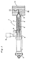
- Fig. 1 is an partially cross sectional explanatory
view schematically showing the construction of an injection
molding apparatus according to an embodiment of the present
invention;
- Fig. 2 is an explanatory front view of a forging
material sample used for a test 1;
- Fig. 3 is an explanatory vertical sectional view
of a forging material sample of the test 1, taken along the
line Y3-Y3 of Fig. 2;
- Fig. 4 is an explanatory vertical sectional view
of a forged member employing the forging material sample of
the test 1;
- Fig. 5 is a perspective view schematically showing
the cavity structure of a molding die used in a test 2 and a
test 3;
- Fig. 6 is a perspective view schematically showing
the shape of a thick molded product according to a test 4, a
test 5 and a test 6;
- Fig. 7 is an explanatory plan view schematically
showing the shape of a molded product according to a test 7;
- Fig. 8 is a perspective view of a forging material
according to a test 8;
- Fig. 9 is an explanatory view schematically
showing the forging process of a forging material according
to the test 8;
- Fig. 10 is an explanatory view showing a forged
member sample obtained through the test 8;
- Fig. 11 is a graph showing a relation between the
pre-forging relative density and the post-forging relative
density, according to the test results of the test 1;
- Fig. 12 is a graph showing a relation between the
gate passage velocity of a light metal molten material and
the relative density of a molded product, according to the
test results of the test 2;
- Fig. 13 is a graph showing a relation between a
ratio (Sg/Sw) of the gate cross-section area of a light
metal molten material to the molding cavity maximum cross-section
area and the relative density of a molded product,
according to the test results of the test 3;
- Fig. 14 is a graph showing a relation between the
gate passage velocity of a light metal molten material and
the relative density of a thick molded product, according to
the test results of the test 4;
- Fig. 15 is a graph showing a relation between a
ratio (Sg/Sw) of the gate cross-section area of a light
metal molten material to the molding cavity maximum cross-section
area and the relative density of a thick molded
product, according to the test results of the test 5;
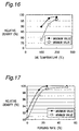
- Fig. 16 is a graph showing a relation between the
die temperature and the relative density of a molded
product, according to the test results of the test 7;
- Fig. 17 is a graph showing a relation between the
forging rate and the relative density of a forged member,
according to the test results of the test 8;
- Fig. 18 is an electron micrograph showing an
example of the metallographic structure of a forged member
in the case where the forging rate is set to 15% in the test
8; and
- Fig. 19 is an electron micrograph showing an
example of the metallographic structure of a forged member
in the case where the forging rate is set to 25% in the test
8.
-
DETAILED DESCRIPTION OF THE PREFERRED EMBODIMENTS
-
Preferred embodiments of the present invention
will be described in detail below with reference to the
accompanying drawings taking the case where the injection
molding method is adopted for the formation of a forging
material as an example.
-
Reference is first made to the formation of a
forging material according to the present embodiment. Fig.
1 is an explanatory view schematically showing the cross
section of part of an injection molding apparatus for
performing injection molding of a light metal forging
material according to an embodiment of the present
invention.
-
As shown in this figure, the injection molding
apparatus 1 is the so-called screw type including a
cylinder 2 that has a nozzle 3 at its tip portion and is to
be heated by a heater 4 provided on its peripheral surface,
a screw 6 that is rotatably supported inside the cylinder 2
and a molding machine body 5 connected with the cylinder 2,
a rotary driver 7 provided with, for example, a motor
mechanism, a speed reducer and so on for rotatively driving
the screw 6, a hopper 8 in which a raw material is loaded
and stored and a feeder 9 for feeding the raw material into
the molding machine body 5 while measuring the raw material
inside the hopper 8.
-
Although not specifically illustrated, the
molding machine body 5 is internally provided with a high-speed
injection mechanism for advancing the screw 6 toward
the nozzle 3 side. This high-speed injection mechanism is
constructed so as to advance the screw 6 in accordance with
specified timing, detect the retreat of the screw 6 by a
predetermined distance when it occurs, stop the rotation of
the screw 6 and concurrently stop the retreating movement
of the screw.
-
The injection molding apparatus 1 is set in
position so that the internal path of the nozzle 3
communicates with a runner portion 12 connected with a
molding cavity 11 and used with the leading end side of the
cylinder 2 joined with a metallic die 10.
-
The raw material loaded and stored in the hopper
8 is measured by a specified amount and fed into the
molding machine body 5 by the feeder 9 and then fed by the
rotating screw 6 into the cylinder 2 put in a heated state.
The fed raw material is heated to a specified temperature
while being sufficiently stirred and kneaded by the
rotation of the screw 6 inside the cylinder 2. According
to the present embodiment, a light metal molten material
put preferably in a semi-solid state at a temperature lower
than the melting point is obtained through this process.
-
As the thus-obtained light metal molten material
in the semi-solid state is squeezed out ahead of the screw
6, the screw 6 is retreated by the pressure. According to
another method, the screw may be forcibly retreated at the
desired speed.
-
If the screw 6 is retreated by the predetermined
distance, then the high-speed injection mechanism (not
shown) inside the molding machine body 5 detects the above
event and stops the rotation of the screw 6 and
concurrently stops the retreating movement. The
measurement of the raw material may be performed by setting
the distance of retreat of the screw 6.
-
Then, by advancing the screw 6 that stops
rotating and is put in the retreated position by the high-speed
injection mechanism (not shown) so as to apply a
specified pressure, the light metal molten material in the
semi-solid state is injected from the nozzle 3 into the
metallic die 10. That is, the light metal molten material
is injected from the nozzle 3 and charged into the molding
cavity 11 via the runner portion 12.
-
In the present embodiment, a magnesium (Mg) alloy
that is a kind of light metal is used as the raw material
and this is fed in the form of, for example, chip-shaped
pellets to the hopper 8 of the injection molding apparatus
1. A passage that extends from the hopper 8 to the inside
of the molding machine body 5 is preferably filled with an
inert gas (argon, for example) for preventing the oxidation
reaction of the raw material (Mg alloy pellets).
-
The molding cavity 11 of the metallic die 10 is
preferably formed into a shape that resembles the shape of
the forming cavity of the forging die (not shown) used for
the forging process to be performed after this injection
molding, and there can be obtained a half-finished
injection molded product (forging material) resembling the
forged member that is the product to be obtained in the
subsequent process.
-
This enables the simplification of the forging
process to only one process of the finishing forging and
enables the forging of even a member of a complicated
shape. Furthermore, even a material of an inferior forging
property can be subjected to the forging process without a
hitch.
-
According to the present embodiment, the
advancement velocity (preferably, also the retreat velocity)
of the screw 6 of the injection molding apparatus 1 is set
to a value of not smaller than 1 [m/s]. The lower limit
value of the screw velocity is set to 1 [m/s] because the
cycle time in the manufacturing stage becomes too long to
cause a lack of practicality if the lower limit is set lower
than this value, although the occurrence of gas defect due
to the involvement of gas in the manufacturing stage of the
forging material can be reduced.
-
Even in the case where a forging material is
molded by the injection molding method carried out by using
a molten material in the completely molten state, it is
preferable to set the screw velocity to a value of not
smaller than 1 [m/s]. Also, even in the case where the
manufacturing of the forging material is carried out by the
die casting method instead of the injection molding method,
it is preferable to set the plunger velocity to a value of
not smaller than 1 [m/s] (meter per second) ].
-
The lower limit value of the plunger velocity of
the die casting method and the screw velocity of the
injection molding method is set to 1 [m/s] because the cycle
time in the manufacturing stage becomes too long to cause a
lack of practicality if the lower limit is lower than this
value, although the occurrence of gas defect due to the
involvement of gas in the manufacturing stage of the forging
material can be reduced.
-
A variety of tests have been performed in order to
obtain a high-quality forging material made of a light metal
alloy that has a small quantity of defects and is molded by
the injection molding apparatus 1 by properly setting the
injection molding conditions, and to make the forged member
obtained by subjecting the forging material to a forging
process have excellent strength characteristics and
soundness by properly setting forging conditions.
-
The tests will be described below. First, the
chemical compositions of the alloys used as samples of these
series of tests are shown in Table 1. It is to be noted
that the alloy B and alloy D among the alloys A through D
shown in Table 1 correspond to ASTM AZ91D, which is normally
considered to be inappropriate for use in the forging works
because of the degraded forging property.
| (Unit: Percent by Weight) |
| | Al | Zn | Mn | Fe | Ni | Cu | Mg |
| Alloy A | 7.2 | 0.2 | 0.22 | 0.003 | 0.0008 | 0.001 | Remainder |
| Alloy B | 9.2 | 0.7 | 0.22 | 0.004 | 0.0008 | 0.002 | Remainder |
| Alloy C | 6.2 | 0.9 | 0.23 | 0.003 | 0.0008 | 0.001 | Remainder |
| Alloy D | 8.9 | 0.7 | 0.24 | 0.003 | 0.0008 | 0.001 | Remainder |
〈Test 1〉
-
Reference is first made to a test 1 that examined
the influence of the relative density in the material stage
(i.e., before forging) exerted on the relative density of
the member obtained through the forging.
-
Figs. 2 and 3 are an explanatory plan view and an
explanatory vertical section view showing the shape of a
forging material sample used in this test. Fig. 4 is an
explanatory vertical section view of the sample obtained
through the forging. In Fig. 3 and Fig. 4, the numbers
representing the dimensions are indicated in millimeters
([mm]). The alloy A among the tour types of the alloy
samples shown in Table 1 was used as a material in the test
-
As is apparent from these figures, the forging
material sample W1m used in this test is formed roughly in a
disk-like shape provided with an annular projection on the
outer peripheral surface of the upper side. A forged member
W1f is obtained by applying a forging pressure to a recess
at the center with in a state in which the material is
regulated by a forging die (not shown) so that the outer
diameter and the width of the annular projection (i.e., the
inner diameter dimension and the outer diameter dimension of
the annular projection) are not changed.
-
In this stage, only the inner diameter and outer
diameter of the annular projection of the forging material
W1m are regulated, and therefore, it is to be plastically
deformed so that the center portion with the recess becomes
thin and the annular projection becomes high. That is, the
forging process for obtaining the forged member W1f shown in
Fig. 4 from the forging material W1m shown in Fig. 2 and
Fig. 3 is carried out by the so-called unclosed forging
method for allowing at least part (the upper surface side of
the annular projection in this case) of the forging material
W1m to be freely plastically deformed instead of being
restrained by the forging die in the forging space that is
defined by the forging die and is not completely closed. As
is well known, in the case of this unclosed forging method,
it is considered very difficult to completely remove the
defects included in the material W1m through the forging
process.
-
The forged member W1f obtained as described above
was subjected to the measurement of the relative density of
the member after the forging when the relative density in
the material stage (i.e., before the forging) was changed
from about 85% to 95%. The measurement results are shown in
Fig. 11.
-
As clearly shown in the graph of Fig. 11, if the
pre-forging relative density is not lower than about 90%,
then the post-forging relative density has a very small
variation between the maximum value and the minimum value,
and the relative density surely exceeds 99% at minimum and
comes to have a very high value close to 100%. If the pre-forging
relative density is lower than about 90%, then the
post-forging relative density has a large variation between
the maximum value and the minimum value as the value
reduces, and the numerical level of the relative density is
sharply reduced.
-
Therefore, unique effects and operations due to
the use of the semi-solid injection molding method are
obtained. Also, by setting the pre-forging relative density
in the material stage to the value of not lower than 90%,
the relative density of the resulting forged member can be
stably kept at a high value (not lower than 99%, for
example) that seems to be practically preferable when the
forging process is carried out with the material. That is,
a sound forged member can be obtained by effectively
removing the defects inside the material generated in the
material molding stage.
-
Even when the Mg alloy that generally seems to
have degraded forging properties is used as a material, a
sound forged member can be obtained by removing the defects
inside the material through the forging process.
-
Furthermore, the semi-solid injection molding
method is used in this test 1, and therefore, the unique
effects and operations due to the use of the semi-solid
injection molding method are obtained in manufacturing the
forging material. When adopting the die casting method or
the normal injection molding method (using a molten material
in a completely molten state), a sufficiently high
productivity can be secured by adopting these processes with
the cycle time in the manufacturing stage properly
maintained by setting the plunger velocity of the die
casting method and the screw velocity of the injection
molding method to a value of not smaller than 1 [m/s].
-
Since the relative density in the material stage
is not lower than 90% even in this case, by carrying out the
forging process by means of the material, the relative
density of the resulting forged member can be stably kept at
a high value (not lower than 99%, for example) that
considered to be practically preferable (even by the
unclosed forging method). This allows a sound forged member
to be obtained by effectively removing the defects such as
gas defect inside the material generated in the material
molding stage.
〈Test 2〉
-
Reference is next made to a test 2 that examined
the influence of the gate passage velocity of the molten
material through the semi-solid injection molding exerted on
the relative density of the molded product (forging
material). In this test 2, the alloy B among the four alloy
samples shown in Table 1 was used as a material.
-
Fig. 5 is an explanatory view schematically
showing the cavity structure of the molding die used in this
test 2. According to this molding die, a runner section Cr1
is connected via a gate section Cg1 to a molding cavity Cw1
corresponding to the shape of the molded product. A molten
material that has flowed through the runner section Cr1 in
the direction of arrow shown in the figure is charged from
the gate section Cg1 having a small passage area Sg (gate
cross-section area) into the molding cavity Cw1. In this
stage, the gate section Cg1 is choked so as to have a gate
cross-section area Sg much smaller than that of the runner
section Cr1, and therefore, the flow velocity of the molten
material is increased when passing through the gate section.
-
In this test 2, the relative density of the molded
product (forging material) when the velocity (gate passage
velocity Vg) of the molten material passing through the gate
section Cg1 was changed was measured. It is to be noted
that the gate passage velocity Vg of this molten material
can be changed by adjusting the molten material injection
velocity from the injection nozzle, the gate cross-section
area Sg or the like.
-
The measurement result is shown in Fig. 12. As
clearly shown in the graph of Fig. 12, it was discovered
that the relative density of the molded product reduced as
the gate passage velocity Vg (gate velocity) increased and
the relative density came under 90% when the gate velocity
exceeded a velocity of about 150 [m/s]. This seems to
depend on the fact that the flow state of the molten
material in the injecting and charging stage becomes more
difficult to be kept in a state close to a laminar flow as
the gate velocity increases.
-
Therefore, when forming a forging material by the
semi-solid injection molding, the molten material can be
injected and charged in the state closer to the laminar flow
into the molding cavity by setting the gate passage velocity
Vg of the molten material to a value of not greater than 150
[m/s], and a forging material having a relative density of
not lower than 90% can be stably obtained.
〈Test 3〉
-
Reference is next made to a test 3 that examined
the influence of a ratio Sg/Sw of a gate cross-section area
Sg shown in Fig. 5 to a maximum cross-section area Sw of the
molding cavity (in the direction roughly perpendicular to
the inflow direction of the molten material) exerted on the
relative density of the molded product (forging material).
-
In this test 3, the relative density of the molded
product (forging material) was measured by changing the
value of the ratio Sg/Sw from 0.02 to 0.1 in the case where
the solid phase rate is 10% and the case where the solid
phase rate is 25%. In this test 3, the alloy B among the
four alloy samples shown in Table 1 was used as a material.
The measurement results are shown in Fig. 13.
-
As clearly shown in the graph of Fig. 13, the
relative density of the forging material is roughly constant
when the ratio Sg/Sw is not smaller than about 0.06, and a
high value of about 99% can be kept. When the ratio Sg/Sw
is not greater than about 0.06, the relative density reduces
as this value reduces. However, even when the ratio Sg/Sw =
0.02 at the lower limit of the measurement range, the
relative density is not lower than 94%, meaning that the
ratio sufficiently exceeds 90% necessary for obtaining a
sound forged member.
-
The relative density reduces as the solid phase
rate reduces. However, according to the graph of Fig. 13,
the molten material can be injected and charged in a state
closer to the laminar flow into the molding cavity, by
setting the ratio Sg/Sw to a value of not smaller than 0.02,
even if it is supposed that the solid phase rate is very low
(in particular, the completely molten state in which the
solid phase rate is 0%), and this allows a forging material
having a relative density of not lower than 90% to be
reliably obtained.
-
The relative density of the resulting molded
product reduces as the value of the ratio Sg/Sw of the gate
cross-section area Sg to the maximum cross-section area Sw
(in the direction roughly perpendicular to the inflow
direction of the molten material) of the molding cavity
reduces presumably because the flow abruptly increases when
the molten material flows from the gate section Cg1 into the
molding cavity Cw1 as the value of this ratio reduces and
because the gas tends to be easily involved due to the
difficulty in maintaining the flow state close to the
laminar flow.
〈Test 4〉
-
Reference is next made to a test 4 that examined
the influence of the gate velocity exerted on the relative
density of the molded product when moldting a thick molded
product (forging material) by semi-solid injection molding.
-
Fig. 6 is a perspective view showing the exterior
shape of a molded product (forging material) to be molded in
this test, where the numbers representing the dimensions are
indicated in millimeters ([mm]). The alloy C and alloy D
among the four types of the alloy samples shown in Table 1
were used as a material.
-
With regard to the thickness of the molded product
(or the casted product), it is an established practical
standerd that the thickness is normally limited to a
thickness of about 6 [mm] in the case of, for example, die
casting method and is limited to a thickness of about 2 to 3
[mm] at most in the case of the injection molding even on a
trial production level. In contrast to this, as shown in
Fig. 6, the forging material of this test has a thickness of
8 [mm] or set to be very thick.
-
In molding the thick forging material by the semi-solid
injection molding, the relative density of the molded
product (forging material) was measured when the velocity
(gate passage velocity Vg) of the molten material passing
through the gate section Cg1 was changed, similarly to the
case of the test 2.
-
In this test 4, the relative density of the molded
product (forging material) was measured by changing the gate
velocity Vg from about 25 [m/s] to 100 [m/s] in the case
where the solid phase rate was 23% (alloy D) and the case
where the solid phase rate was 40% (alloy C). Further,
measurement was performed by setting the ratio Sg/Sw of the
gate cross-section area Sg to the molding cavity maximum
cross-section area Sw (in the direction roughly
perpendicular to the inflow direction of the molten
material) of the molding cavity to a value of 0.2 and making
the gate passage velocity Vg [mm/s], the gate cross-section
area Sg [mm2] and the molding cavity capacity Wv [mm3] have a
relation expressed by Vg · Sg/Wv ≥ 10.
-
The measurement results are shown in Fig. 14. As
clearly shown in the graph of Fig. 14, the relative density
of the forging material is roughly constant and a high value
of about 99% can be kept when the gate velocity Vg is not
greater than about 80 [m/s]. When the gate velocity Vg is
greater than about 80 [m/s], the relative density reduces as
this value increases. However, the relative density is not
smaller than 94% even at the upper limit of the measurement
range expressed by Vg = 100 [m/s], and this value
sufficiently exceeds 90% necessary for obtaining a sound
forged member.
-
The relative density reduces as the solid phase
rate reduces. According to the graph of Fig. 14, the molten
material can be easily injected and charged in a state
closer to the laminar flow into the molding cavity, even if
it is supposed that the solid phase rate is very low (in
particular, the completely molten state in which the solid
phase rate is 0%), and this allows a forging material having
a relative density of not lower than 90% to be reliably
obtained.
-
Therefore, even if the molded product is thick or
assuming that the solid phase rate is very low (in
particular, the completely molten state in which the solid
phase rate is 0%), the molten material can be injected and
charged in a state closer to the laminar flow into the
molding cavity in molding a forging material through the
semi-solid injection molding by setting the gate passage
velocity Vg of the molten material to a value of not greater
than 100 [m/s], and this allows a forging material having a
relative density of not lower than 90% to be stably obtained
with the quantity of defects effectively restrained.
-
More preferably, a forging material having a
higher relative density can be stably obtained by setting
the gate passage velocity Vg of the molten material to a
value of not greater than 80 [m/s].
〈Test 5〉
-
Reference is next made to a test 5 that examined
the influence of the ratio Sg/Sw of the gate cross-section
area Sg to the maximum cross-section area Sw of the molding
cavity (in the direction roughly perpendicular to the inflow
direction of the molten material) exerted on the relative
density of the molded product (forging material) when a
thick molded product (forging material) shown in Fig. 6 is
formed by the semi-solid injection molding.
-
In this test 5, the relative density of the molded
product (forging material) was measured by changing the
value of the ratio Sg/Sw within a range of 0.02 to 0.5 in
the case where the solid phase rate was 23%. Furthermore,
this test was carried out by setting the gate passage
velocity Vg to 45 [m/s]. In this test 5, the alloy D among
the four types of the alloy samples shown in Table 1 was
used as a material. The measurement result is shown in Fig.
15.
-
As clearly shown in the graph of Fig. 15, the
relative density of the forging material is roughly constant
and a high value of not lower than 99% can be kept when the
ratio Sg/Sw is not smaller than about 0.1. When the ratio
Sg/Sw is smaller than about 0.1, the relative density
sharply reduces as this value reduces. However, even when
the ratio Sg/Sw = 0.02 at the lower limit of the measurement
range, the relative density is not lower than 93%, meaning
that the ratio sufficiently exceeds 90% necessary for
obtaining a sound forged member.
-
Therefore, by setting the ratio Sg/Sw of the gate
cross-section area Sg to the maximum cross-section area Sw
of the molding cavity (in the direction roughly
perpendicular to the inflow direction of the molten
material) to a value of not smaller than 0.1, the molten
material can be injected and charged in a state closer to
the laminar flow into the molding cavity, and a forging
material having a relative density of not lower than 90% can
be more stably obtained. Furthermore, even when molding a
thick forging material, a forging material having a relative
density of not lower than 90% can be more stably obtained by
effectively restraining the quantity of defects.
〈Test 6〉
-
Reference is next made to a test 6 that examined
the influence of the relation between the gate passage
velocity Vg [mm/s], the gate cross-section area Sg [mm2] and
the molding cavity capacity Wv [mm3] exerted on the charging
property of the molten material into the molding cavity when
the thick molded product (forging material) shown in Fig. 6
is formed by the semi-solid injection molding. It is to be
noted that the alloy C and alloy D among the four types of
the alloy samples shown in Table 1 were each used as a
material.
-
In this test 6, molding was carried out by
changing the value of Vg · Sg/Wv within a range of 5 to 150
in the case where the solid phase rate is 40% (alloy C) and
the case where the solid phase rate is 52% (alloy D), and
the presence or absence of the faulty charging of each
molded product was examined. This sixth test was carried
out by setting the value of ratio Sg/Sw of the gate cross-section
area Sg to the maximum cross-section area Sw (in the
direction roughly perpendicular to the inflow direction of
the molten material) of the molding cavity to 0.2 and
setting the gate passage velocity Vg to a value of not
greater than 80 [m/s].
-
The test results are shown in the following Table
2.
| Alloy | Solid Phase Rate | Vg.Sg/Wv | Faulty Charging |
| C |
| | 40 | 5 | Present |
| 10 | Absent |
| 30 | Absent |
| 70 | Absent |
| 150 | Absent |
| D | 52 | 5 | Present |
| 10 | Absent |
| 30 | Absent |
| 70 | Absent |
| 150 | Absent |
-
As clearly shown in of Table 2, the faulty
charging occurred when the value of Vg ·Sg/Wv was five and
the faulty charging did not occur when this value is not
smaller than ten, regardless of the solid phase rate.
-
Therefore, by making the gate passage velocity Vg
[mm/s], the gate cross-section area Sg [mm2] and the molding
cavity capacity Wv [mm3] have a relation expressed by Vg ·
Sg/Wv ≥ 10, the concern about the possible occurrence of
faulty charging can be eliminated even when molding a thick
forging material.
-
Furthermore, even in this case, by setting the
gate passage velocity Vg of the molten material to a value
of not greater than 80 [m/s], the molten material can be
injected and charged in a state much closer to the laminar
flow into the molding cavity, and a forging material having
a relative density of not lower than 90% can be much more
stably obtained. Furthermore, even when molding a thick
forging material, a forging material having a relative
density of not lower than 90% can be more stably obtained by
effectively restraining the quantity of defects.
〈Test 7〉
-
Reference is next made to a test 7 that examined
the influence of the molding die temperature (die
temperature) exerted on the relative density of the molded
product (forging material) when a thick molded product is
formed by the semi-solid injection molding.
-
Fig. 7 is an explanatory plan view of a molded
product W3 of this test 7, where the reference numerals Wr3
and Wf3 indicate the imaginary portions corresponding to a
runner section and an overflow section, respectively, in the
molding die. It is to be noted that the numbers
representing the dimensions are indicated in millimeters
([mm]) in Fig. 7, where the thickness of the gate section
and the thickness of the molded product W3 are set to 2 [mm]
and 10 [mm], respectively. In this test 7, the alloy A
among the four types of alloy samples shown in Table 1 was
used as a material.
-
In this test 7, molding was carried out by
changing the die temperature within a range of 100°C to
200°C in the case where the solid phase rate is 20%, and the
relative density of each resulting molded product (forging
material) was measured. In connection with this
measurement, the molded product W3 was divided into 15 parts
as shown in Fig. 7, and the relative densities of the
divided parts were measured to examine the magnitude of
variation. The measurement results are shown in Fig. 16.
-
As clearly shown in the graph of Fig.16, the
relative density of the resulting molded product is lower
and the variation becomes greater as the setting value of
the die temperature becomes lower. However, it was
discovered that a relative density of not lower than 90%
could be obtained, even at the lower limit value of the
variation, by keeping the die temperature not lower than
150°C.
-
With regard to the upper limit value of the die
temperature, it is known that the troubles such as the
excessive occurrence of "burr" or the easy leak of the
molten material from the die matching surface of the molding
die tend to easily occur when the die temperature is set to
a temperature of not lower than about 350°C.
-
That is, by carrying out the molding by keeping
the molding die temperature of not lower than 150°C and
lower than 350°C, the troubles such as the excessive
occurrence of "burr" or the easy leak of the molten material
from the die matching surface of the molding die are
avoided, and a forging material having a relative density of
not lower than 90% can be stably obtained even for a thick
molded product.
〈Test 8〉
-
Reference is next made to a test 8 that examined
the influence of the forging rate in the forging process
exerted on the relative density of the forged member.
-
Figs. 8 through 10 schematically show the method
of obtaining samples of the forged member with an Mg alloy
forging material in this test 8. In this test, as shown in
Fig. 8, a rectangular parallelepiped magnesium alloy forging
material M1 having the dimensions of A1 (height) × B1
(width) × L1 (length) was prepared, held between a pair of
fixing plates P1 so as to be checked in, for example, the
widthwise direction of this material M and subjected to
plastic working (forging process) with a compression load
applied in the vertical direction (a direction perpendicular
to sheet surface in Fig. 9) in this state, for the formation
of a sample of the forged member as shown in Fig. 10.
-
As a result, the dimension in the vertical
direction of the material M1 is changed from the initial
value A1 to A2 (shortened), and the length is changed from
the initial value L1 to L2 (elongated). In this case, the
forging rate of this forging is calculated according to the
following equation (1):
forging rate = (A1 - A2)/A1 × 100[%]
-
In the present embodiment, the initial basic
dimensions (see Fig. 8) of the forging material M1 was set
to the values of A1= A2= 12 [mm] and L1 = 50 [mm]. The
thus-obtained forged member samples were subjected as
specimens to the measurement of the relative density.
-
In this test 8, the forging materials having a
relative density of 90% to 92.5% before forging (forging
rate is 0%) were subjected to a forging process while
varying the forging rate within a range of 0 to 50%, and the
relative densities of the resulting forged products were
measured. In this test 8, the alloy A among the four alloy
samples shown in Table 1 was used as a material.
-
The test results are shown in Fig. 17. Electron
micrographs (each having a magnification of 50 times)
showing examples of the metallographic structures of forged
members in the case where the forging rate is 15% and the
case where the forging rate is 25% are shown in Fig. 18 and
Fig. 19, respectively.
-
As clearly shown in the graph of Fig. 17, the
relative density of the forged member is close to a constant
value and a high value exceeding about 99% can be kept when
the forging rate is not lower than about 25%. When the
forging rate is lower than about 25%, the relative density
sharply reduces as the forging rate reduces, and the
variation between the maximum value and the minimum value
increases.
-
That is, the compression force exerted on the
material through the forging process is consumed for the
purpose of removing the defects inside the material and
making the material sound when the forging rate is lower
than about 25%. In order to increase the strength through
the forging by further plastically deforming the material
after the removal of the defects inside the material, the
forging rate must be set not lower than 25%.
-
According to the electron micrographs shown in
Fig. 18 and Fig. 19, the portions existing in the form of
black lumps or dots are the defective portions. It can be
found that the defects are rather minimized when the forging
rate is 25% than when the forging rate is 15%.
-
According to the above description, the relative
density of the resulting forged member can be kept at a high
value (not lower than 99%, for example) that seems to be
practically preferable, by setting the forging rate not
lower than 25%. That is, a sound forged member can be
obtained by effectively removing the defects inside the
material generated in the material molding stage.
-
As described above, according to the present
embodiment, by setting the relative density in the material
(forging material) stage to a value of not lower than 90%,
the relative density of the forged member obtained through
the forging process using this material can be stably
secured at a very high value. In the case of the semi-solid
injection molding, by properly setting the factors of the
gate cross-section area of the molding die, the gate passage
velocity of the molten material, the volume and maximum
cross-section area of the molding cavity and so on, the
relative density of the resulting molded product (forging
material) can be effectively improved to allow the quantity
of defects to be reduced. Furthermore, by setting the
forging rate not lower than 25% in forging a forging
material having a relative density of not lower than 90%,
the defects inside the material generated in the material
molding state can be effectively removed to allow a sound
forged member to be obtained.
-
The aforementioned embodiments have been described
on the basis of the case where the semi-solid injection
molding method is used for the molding of the forging
material. However, the present invention is not limited to
this and is able to be effectively applied to the case where
a variety of other processes are adopted for the molding of
a forging material by the semi-solid casting method, the
injection molding method using a light metal molten material
in the completely molten state or the casting method of, for
example, the die casting method. Although the
aforementioned embodiments used the Mg alloy as a material
to be injected, the present invention can also be
effectively applied to the case where a light metal of
another kind is used as a material.
-
As described above, the present invention is
limited to neither one of the aforementioned embodiments and
is, of course, allowed to be subjected to a variety of
modifications and improvements in terms of design within a
scope not departing from the essence thereof.
ADVANTAGES OF THE INVENTION
-
According to the forging material of the first
aspect of the present invention, the plunger velocity of the
die casting method and the screw velocity of the injection
molding method are each set not smaller than 1 [m/s]. With
this arrangement, the cycle time in the manufacturing stage
is properly maintained, and a sufficiently high productivity
can be secured by adopting these processes. In this case,
the relative density is not lower than 90% in the material
stage. Therefore, by carrying out the forging process using
the material, the relative density of the forged member
obtained (even in the case of the so-called unclosed forging
method) can be kept at a high value (not lower than 99%, for
example) that seems to be practically preferable. That is,
a sound forged member can be obtained by removing the
defects such as gas defect inside the material generated in
the material molding stage.
-
According to the second aspect of the present
invention, basically effects similar to those of the above
aspect of the invention can be produced. Specifically, the
particular effects and operations due to the use of the
semi-solid injection molding method can be obtained, and the
relative density is not lower than 90% in the material
stage. Therefore, by carrying out the forging process using
the material, the relative density of the forged member
obtained (even in the case of the so-called unclosed forging
method) can be stably kept at a high value (not lower than
99%, for example) that seems to be practically preferable.
That is, a sound forged member can be obtained by removing
the defects inside the material generated in the material
molding stage.
-
According to the third aspect of the present
invention, basically effects similar to those of the above
aspect of the invention can be produced. In particular,
even when the Mg alloy that is generally considered to have
a degraded forging property is used as a material, the
defects inside the material are effectively removed through
the forging process, allowing a sound forged member to be
obtained.
-
According to the forging material molding method
of the fourth aspect of the present invention, the
particular effects and operations due to the use of the
semi-solid injection molding method can be obtained, and the
gate passage velocity Vg of the molten material is set not
greater than 150 [m/s] in molding the forging material by
this semi-solid injection molding. With this arrangement,
the molten material can be injected and charged into the
molding cavity in a state closer to the laminar flow, and a
forging material having a relative density of not lower than
90% can be stably obtained. Furthermore, by setting the
ratio Sg/Sw of the gate cross-section area Sg to the molding
cavity maximum cross-section area Sw (in the direction
roughly perpendicular to the inflow direction of the molten
material) to the value of not smaller than 0.02, the molten
material can be injected and charged in a state closer to
the laminar flow into the molding cavity even if it is
supposed that the solid phase rate is very low (in
particular, the completely molten state in which the solid
phase rate is 0%), and this allows a forging material having
a relative density of not lower than 90% to be obtained.
-
Then, by carrying out the forging process using a
forging material having a relative density of not lower than
90% in the material stage, the relative density of the
forged member obtained (even in the case of the so-called
unclosed forging) can be stably kept at a high value (not
lower than 99%, for example) that seems to be practically
preferable. That is, a sound forged member can be obtained
by removing the defects inside the material generated in the
material molding stage.
-
According to the fifth aspect of the present
invention, basically effects similar to those of the above
aspect of the invention can be produced. In particular,
even when molding a thick forging material or even if it is
supposed that the solid phase rate is very low (in
particular, the completely molten state in which the solid
phase rate is 0%), by setting the gate passage velocity Vg
of the molten material to a value of not greater than 100
[m/s], the molten material can be injected and charged in a
state closer to the laminar flow into the molding cavity,
and this allows a forging material having a relative density
of not lower than 90% to be more stably obtained by
effectively restraining the quantity of defects.
-
According to the sixth aspect of the present
invention, basically effects similar to those of the above
aspect of the invention can be produced. In particular, the
gate passage velocity Vg of the molten material is set not
greater than 80 [m/s]. This allows the molten material to
be injected and charged in a state closer to the laminar
flow into the molding cavity and allows a forging material
having a relative density of not lower than 90% to be more
stably obtained. Even when molding a thick forging
material, a forging material having a relative density of
not lower than 90% can be more stably obtained by
effectively restraining the quantity of defects.
-
According to the seventh aspect of the present
invention, basically effects similar to those of the avove
aspect of the nvention can be produced. In particular, the
ratio Sg/Sw of the gate cross-section area Sg to the molding
cavity maximum cross-section area Sw (in the direction
roughly perpendicular to the inflow direction of the molten
material) is set not smaller than 0.1. This allows the
molten material to be injected and charged in a state closer
to the laminar flow into the molding cavity and allows a
forging material having a relative density of not lower than
90% to be more stably obtained. Even when molding a thick
forging material, a forging material having a relative
density of not lower than 90% can be more stably obtained by
effectively restraining the quantity of defects.
-
According to the eighth aspect of the present
invention, basically effects similar to those of the above
aspect of the invention can be produced. In particular, the
gate passage velocity Vg of the molten material is set not
greater than 80 [m/s]. This allows the molten material to
be injected and charged in a state much closer to the
laminar flow into the molding cavity and allows a forging
material having a relative density of not lower than 90% to
be more stably obtained. Even when molding a thick forging
material, a forging material having a relative density of
not lower than 90% can be more stably obtained by
effectively restraining the quantity of defects.
-
Also, the gate passage velocity Vg [mm/s], the
gate cross-section area Sg [mm2] and the molding cavity
capacity Wv [mm3] have the relation expressed by Vg · Sg/Wv ≥
10. This eliminates the concern about the possible
occurrence of defective charging even when molding a thick
forging material.
-
According to the ninth aspect of the present
invention, basically effects similar to those of the above
aspect of the invention can be produced. In particular, the
molding is carried out with the molding die temperature set
not lower than 150°C and lower than 350°C. With this
arrangement, a forging material having a relative density of
not lower than 90% can be more stably obtained, while
avoiding the troubles such as the excessive occurrence of
"burr" and the easy leak of the molten material from the die
matching surface of the molding die.
-
According to the forging material molding
apparatus of the tenth aspect of the present invention, the
particular effects and operations due to the use of the
semi-solid injection molding method are obtained. In
molding the forging material through this semi-solid
injection molding, the gate passage velocity Vg of the
molten material is set not greater than 150 [m/s].
Therefore, the molten material can be injected and charged
in a state closer to the laminar flow into the molding
cavity, and a forging material having a relative density of
not lower than 90% can be stably obtained. The ratio Sg/Sw
of the gate cross-section area Sg to the molding cavity
maximum cross-section area Sw (in the direction roughly
perpendicular to the inflow direction of the molten
material) is set not smaller than 0.02. Therefore, the
molten material can be injected and charged in a state
closer to a laminar flow into the molding cavity, even if it
is supposed that the solid phase rate is very low (in
particular, the completely molten state in which the solid
phase rate is 0%), and this allows a forging material having
a relative density of not lower than 90% to be obtained.
-
Then, by carrying out the forging process using
the forging material having a relative density of not lower
than 90% in the material stage, the relative density of the
forged member obtained (even in the case of the so-called
unclosed forging) can be stably kept at a high value (not
lower than 99%, for example) that seems to be practically
preferable. That is, a sound forged member can be obtained
by effectively removing the defects inside the material
generated in the material molding stage.
-
According to the eleventh aspect of the present
invention, basically effects similar to those of the above
aspect of the invention can be produced. In particular, the
gate passage velocity Vg of the molten material is set not
greater than 100 [m/s] . Therefore, the molten material can
be injected and charged in a state closer to the laminar
flow into the molding cavity even when molding a thick
forging material or if it is supposed that the solid phase
rate is very low (in particular, the completely molten state
in which the solid phase rate is 0%), and this allows a
forging material having a relative density of not lower than
90% to be more stably obtained by effectively restraining
the quantity of defects.
-
According to the twelfth aspect of the present
invention, basically effects similar to those of the above
aspect of the invention can be produced. In particular, the
gate passage velocity Vg of the molten material is set not
greater than 80 [m/s]. This allows the molten material to
be injected and charged in a state closer to the laminar
flow into the molding cavity and allows a forging material
having a relative density of not lower than 90% to be more
stably obtained. Even when molding a thick forging
material, a forging material having a relative density of
not lower than 90% can be more stably obtained by
effectively restraining the quantity of defects.
-
Aaccording to the thirteenth aspect of the present
invention, basically effects similar to those of the above
aspect of the invention can be produced. In particular, the
ratio Sg/Sw of the gate cross-section area Sg to the molding
cavity maximum cross-section area Sw (in the direction
roughly perpendicular to the inflow direction of the molten
material) is set not smaller than 0.1. This allows the
molten material to be injected and charged in a state much
closer to the laminar flow into the molding cavity and
allows a forging material having a relative density of not
lower than 90% to be more stably obtained. Also, even when
molding a thick forging material, a forging material having
a relative density of not lower than 90% can be more stably
obtained by effectively restraining the quantity of defects.
-
According to the fourteenth aspect of the present
invention, basically effects similar to those of the above
aspect of the invention can be produced. In particular, the
gate passage velocity Vg of the molten material is set not
greater than 80 [m/s]. This allows the molten material to
be injected and charged in a state closer to the laminar
flow into the molding cavity and allows a forging material
having a relative density of not lower than 90% to be more
stably obtained. Also, even when molding a thick forging
material, a forging material having a relative density of
not lower than 90% can be more stably obtained by
effectively restraining the quantity of defects.
-
Furthermore, the gate passage velocity Vg [mm/s],
the gate cross-section area Sg [mm2] and the molding cavity
capacity Wv [mm3] have the relation expressed by Vg · Sg/Wv ≥
10. This can eliminate the concern about the possible
occurrence of defective charging even when molding a thick
forging material.
-
According to the fifteenth aspect of the present
invention, basically effects similar to those of the above
aspect of the invention can be produced. In particular, the
molding die temperature is set not lower than 150°C and
lower than 350°C. With this arrangement, a forging material
having a relative density of not lower than 90% can be more
stably obtained while avoiding the troubles such as the
excessive occurrence of "burr" and the easy leak of the
molten material from the die matching surface of the molding
die.
-
According to the forged member manufacturing
method of the sixteenth aspect of the present invention, the
forging material molded by the molding method of either one
of the fourth through ninth inventive aspects is forged at a
forging rate of not lower than 25%. Therefore, basically
effects similar to those of any one of the fourth through
ninth inventive aspects can be produced. Furthermore, the
relative density of the obtained forging material can be
stably kept at a high value (not lower than 99%, for
example) that seems to be practically preferable. That is,
a sound forged member can be obtained by effectively
removing the defects inside the material generated in the
material molding stage.