EP1039169A1 - Balance weight - Google Patents
Balance weight Download PDFInfo
- Publication number
- EP1039169A1 EP1039169A1 EP00106148A EP00106148A EP1039169A1 EP 1039169 A1 EP1039169 A1 EP 1039169A1 EP 00106148 A EP00106148 A EP 00106148A EP 00106148 A EP00106148 A EP 00106148A EP 1039169 A1 EP1039169 A1 EP 1039169A1
- Authority
- EP
- European Patent Office
- Prior art keywords
- weight
- index
- block
- central portion
- weight block
- Prior art date
- Legal status (The legal status is an assumption and is not a legal conclusion. Google has not performed a legal analysis and makes no representation as to the accuracy of the status listed.)
- Granted
Links
- 239000000463 material Substances 0.000 claims abstract description 7
- 241000826860 Trapezium Species 0.000 claims description 2
- 230000007423 decrease Effects 0.000 claims description 2
- XEEYBQQBJWHFJM-UHFFFAOYSA-N Iron Chemical compound [Fe] XEEYBQQBJWHFJM-UHFFFAOYSA-N 0.000 description 8
- 238000005303 weighing Methods 0.000 description 7
- 229910052742 iron Inorganic materials 0.000 description 4
- 241001272720 Medialuna californiensis Species 0.000 description 1
- 238000012986 modification Methods 0.000 description 1
- 230000004048 modification Effects 0.000 description 1
Images



Classifications
-
- F—MECHANICAL ENGINEERING; LIGHTING; HEATING; WEAPONS; BLASTING
- F16—ENGINEERING ELEMENTS AND UNITS; GENERAL MEASURES FOR PRODUCING AND MAINTAINING EFFECTIVE FUNCTIONING OF MACHINES OR INSTALLATIONS; THERMAL INSULATION IN GENERAL
- F16F—SPRINGS; SHOCK-ABSORBERS; MEANS FOR DAMPING VIBRATION
- F16F15/00—Suppression of vibrations in systems; Means or arrangements for avoiding or reducing out-of-balance forces, e.g. due to motion
- F16F15/32—Correcting- or balancing-weights or equivalent means for balancing rotating bodies, e.g. vehicle wheels
- F16F15/324—Correcting- or balancing-weights or equivalent means for balancing rotating bodies, e.g. vehicle wheels the rotating body being a vehicle wheel
- F16F15/328—Multiple weights on adhesive strip
Definitions
- the present invention relates to a balance weight which is adhered to a wheel of an automobile.
- balance weight such as the one made of lead has been used. Contrary to this practice, non-lead balance weight is required for an enhanced natural environment protection in recent years. Iron is the one that has replaced lead. However, use of iron does not permit deforming the balance weight in accordance with the radius of curvature of the tire wheel. Namely, balance weights made of iron cannot be commonly used for various tire wheels having different radii.
- Japanese Registered Utility Model Publication No. 3051328 describes a balance weight having weight blocks.
- the balance weight comprises 1) a central portion; 2) first and second side portions interposing therebetween the central portion such that the first side portion, the central portion and the second side portion are continuously arranged in a direction; 3) a first weight block contained in the first side portion, the first weight block being adjacent to the central portion and having a first width; 4) a second weight block contained in the second side portion, the second weight block being adjacent to the central portion and having a second width; 5) at least one index weight block for indicating a center of the balance weight in the direction, the at least one index weight block being contained in the central portion and having a third width that is shorter than each of the first and second widths; and 6) a base member for uniting together the first and second weight blocks and the at least one index weight block, the base member being made of a flexible material.
- Fig. 1 is a perspective view of a balance weight 10, according to a first preferred embodiment of the present invention.
- each of the weight blocks 9, 1L and 1R is made of a material other than lead, for example, iron.
- each of the weight blocks 9, 1L and 1R has a section, when each of weight blocks 9, 1L and 1R is cut straight through in a direction in which they are arranged, having a shape such that a width of the section in the direction at a point decreases, as a distance between the point and the base member 3 increases.
- the section is shaped into a trapezium having one pair of parallel sides.
- the shape of the section is not particularly limited. Other shapes such as triangle, mountain or half-moon are allowed.
- the balance weight 10 has a base member 3 which is made of a flexible material such as a double-sided tape.
- the base member 3 has a first side to which an index weight block 9 and first and second weight blocks 1L and 1R are bonded, and a second side covered with a releasable paper 5.
- first and second weight blocks 1L and 1R are referred to as other weight blocks 1.
- the index weight block 9 weighs 5 g, and each of the other weight blocks 1 weighs 10 g.
- the index weight block 9 is a half in width of each of the other weight blocks 1.
- the index weight block 9 works for indicating the center of the balance weight 10 in the direction.
- the index weight block 9 has on an upper surface thereof a mark 9a for indicating a center of the width of the index weight block 9, and thus indicating the center of the balance weight 10 since the index eight block 9 is positioned at the center of the balance weight 10.
- the mark 9a is a dented mark.
- each of the other weight blocks 1 has a mark 1a.
- the mark 1a is not used for indicating the center of the balance weight 10.
- Use of the mark 1a for indicating the center of the balance weight is to be stated in the aftermentioned second and third embodiments.
- the balance weight 10 is mounted on a tire wheel 7 in such a manner that an assembly worker releases the paper 5, and then allows the center of the balance weight 10 to mate with a point which has been predetermined by balancing. Thereafter, the balance weight is bonded to the tire wheel by the assembly worker.
- the balance weight 10 can be mounted accurately and with ease on various tire wheels having different curvatures.
- the mark 9a on an upper surface of the weight block 9 helps the assembly worker mount the balance weight 10 accurately and easily.
- Fig. 4 shows combinations of the weight blocks 9 and 1 which are united in series on the base member 3.
- the central portion consists of an even number of index weight blocks 9, the total number of weight blocks of the balance weight 10 is even in number.
- the central portion consists of an odd number of index weight blocks 9, the total number of weight blocks of the balance weight 10 is odd in number.
- the total number of weight blocks is three, namely, an odd number. Therefore, the number of index weight blocks 9 is one, namely, an odd number.
- the total number of weight blocks is six, namely, an even number. Therefore, the number of index blocks 9 is an even number, two. The same is true of No. 12, No. 14, No. 16, No. 18 and No. 20.
- the central portion of the series of the balance weight 10 becomes easy to identify with the index weight block 9 whether singular or plural.
- the index weight block 9 that is one in number is identified such that the center of the series can be easily indicated as being the center line of the index weight block 9 between the marks 9a and 9a.
- the center of the series can be easily identified as being the center line of the index weight block 9 positioned in the middle of the central portion.
- the boundary between two adjacent weight blocks 9, which are positioned in the middle of the central portion can be identified as being the center of the balance weight 10.
- the index weight block 9 is five or less in number. By identifying a gathering of the index weight blocks 9, the assembly worker can accurately and easily determine the center of the balance weight 10. Although not shown in the drawings, the index weight block 9 can be made more than five in number. It should be noted that the weight block combinations No. 1, No. 2, No. 3, No. 4 No. 6 and No. 8 do not belong to the invention.
- Fig. 5 shows a second preferred embodiment of the present invention, in which each of the index weight blocks 9 is one of 5 g and 10 g, and each of the other weight blocks 1 is 15 g or 10 g.
- the second embodiment is based on the same combinational concept as that of the first embodiment in Fig. 4. Namely, each of No. 1, No. 4, No. 5, No. 7, No. 9 and No. 11 has at least one index weight block 9 weighing 5 g for indicating the center of the balance weight 10, while each of No. 2, No. 6 and No. 12 has one index weight block 9 weighing 10 g for indicating the center of the balance weight 10.
- the boundary between two adjacent index weight blocks 9 each weighing 10 g works for indicating the center of the balance weight 10.
- the boundary between two adjacent index weight blocks 9 each weighing 5 g works for indicating the center of the balance weight 10.
- Fig. 6 shows a third preferred embodiment of the present invention, in which each of the index weight blocks 9 is one of 5 g and 10 g, and each of the other weight block 1 is 12.5 g or 10 g.
- the third embodiment is based on the same combinational concept as those of the first and second embodiments in Figs. 4 and 5.
- each of the index weight blocks 9 weighing 5 g works for indicating the center of the balance weight 10.
- the index weight block 9 weighing 10 g works for indicating the center of the balance weight 10.
- the boundary between two adjacent index weight blocks weighing 10 g works for indicating the center of the balance weight 10.
- Fig. 7 shows a fourth embodiment of the present invention.
- the central portion of the balance weight 10 contains at least one other weight block of 10 g each being interposed between two adjacent index weight blocks of 5 g.
- the central portion contains an odd number of at least one other weight block , the total number of the index weight blocks is even in number.
- the central portion contains an even number of at least one other weight block , the total of the index weight blocks is odd in number.
- an even number of index weight blocks of 5 g namely two index weight blocks interpose therebetween one other weight block of 10 g.
- No. an even number of index weight blocks of 5 g, namely two index weight blocks interpose therebetween one other weight block of 10 g.
- an odd number of index weight blocks of 5 g namely three index weight blocks 9 are contained in the central portion, both ends of the central portion are occupied by the index weight blocks of 5 g, and one other weight block of 10 g is interposed between the index weight blocks of 5 g. Therefore, in the case of No. 1, two index weight blocks 9 work for indicating the central portion of the series of the balance weight 10, and the one other weight block of 10 g interposed therebetween works for indicating the center of the series of the balance weight 10. With this, mounting the balance weight 10 becomes easy. Moreover in this case, putting the mark 1a on the one other weight block makes it easier to indicate the center of the balance weight 10, thus leading to still easier mounting. On the other hand, in the case of No.
- each of the other weight blocks interposed between two adjacent index weight blocks 5 g weighs 10 g.
- This weight is not particularly limited to 10 g. It can be 12.5 g, 15 g or the like.
Landscapes
- Engineering & Computer Science (AREA)
- General Engineering & Computer Science (AREA)
- Physics & Mathematics (AREA)
- Acoustics & Sound (AREA)
- Aviation & Aerospace Engineering (AREA)
- Mechanical Engineering (AREA)
- Golf Clubs (AREA)
- Tires In General (AREA)
Abstract
Description
- The present invention relates to a balance weight which is adhered to a wheel of an automobile.
- For correcting an unbalanced condition of a tire wheel, a balance weight such as the one made of lead has been used. Contrary to this practice, non-lead balance weight is required for an enhanced natural environment protection in recent years. Iron is the one that has replaced lead. However, use of iron does not permit deforming the balance weight in accordance with the radius of curvature of the tire wheel. Namely, balance weights made of iron cannot be commonly used for various tire wheels having different radii.
- Japanese Registered Utility Model Publication No. 3051328 describes a balance weight having weight blocks.
- It is an object of the present invention to provide a balance weight having at least one index weight block for indicating easily the center of the balance weight. It is another object of the present invention to provide a balance weight of which weight blocks are made of a material other than lead. It is still another object of the present invention to provide a balance weight that can be used for various tire wheels having different diameters. There is provided a balance weight for providing a balance, according to the present invention. The balance weight comprises 1) a central portion; 2) first and second side portions interposing therebetween the central portion such that the first side portion, the central portion and the second side portion are continuously arranged in a direction; 3) a first weight block contained in the first side portion, the first weight block being adjacent to the central portion and having a first width; 4) a second weight block contained in the second side portion, the second weight block being adjacent to the central portion and having a second width; 5) at least one index weight block for indicating a center of the balance weight in the direction, the at least one index weight block being contained in the central portion and having a third width that is shorter than each of the first and second widths; and 6) a base member for uniting together the first and second weight blocks and the at least one index weight block, the base member being made of a flexible material.
-
- Fig. 1 is a perspective view of a balance weight according to a first preferred embodiment of the present invention;
- Figs. 2(a) is a top view of an index weight block of the balance weight in Fig. 1;
- Fig. 2(b) is a side view of the index weight block of Fig. 2(a);
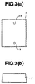
- Figs. 3(a) is a top view of one of first and second weight blocks of the balance weight in Fig. 1;
- Fig. 3(b) is a side view of one of first and second weight blocks of Fig. 3(a);
- Fig. 4 is a table showing combinations of weight blocks, containing those combinations according to the first preferred embodiment of the present invention;
- Fig. 5 is a table showing combinations of weight blocks, according to a second preferred embodiment of the present invention;
- Fig. 6 is a table showing combinations of weight blocks, according to a third preferred embodiment of the present invention;
- Fig. 7 is a table showing combinations of weight blocks, according to a fourth preferred embodiment of the present invention; and
- Fig. 8 is a side view showing a condition in which the balance weight in Fig. 1 is mounted on an automobile wheel.
-
- Fig. 1 is a perspective view of a
balance weight 10, according to a first preferred embodiment of the present invention. - In this embodiment, there are provided one
index weight block 9 and three each of first andsecond weight blocks index weight block 9 is contained in a central portion of thebalance weight 10. Each of theweight blocks weight blocks weight blocks base member 3 increases. In this embodiment, the section is shaped into a trapezium having one pair of parallel sides. However, the shape of the section is not particularly limited. Other shapes such as triangle, mountain or half-moon are allowed. - The
balance weight 10 has abase member 3 which is made of a flexible material such as a double-sided tape. Thebase member 3 has a first side to which anindex weight block 9 and first andsecond weight blocks releasable paper 5. - Hereinafter, the first and
second weight blocks other weight blocks 1. - In this embodiment, the
index weight block 9 weighs 5 g, and each of theother weight blocks 1 weighs 10 g. Theindex weight block 9 is a half in width of each of theother weight blocks 1. Theindex weight block 9 works for indicating the center of thebalance weight 10 in the direction. - Moreover, as is seen in Fig. 2(a), the
index weight block 9 has on an upper surface thereof amark 9a for indicating a center of the width of theindex weight block 9, and thus indicating the center of thebalance weight 10 since the index eightblock 9 is positioned at the center of thebalance weight 10. Themark 9a is a dented mark. - As is seen in Figs. 1 and 3(a), each of the
other weight blocks 1 has amark 1a. In this embodiment, themark 1a is not used for indicating the center of thebalance weight 10. Use of themark 1a for indicating the center of the balance weight is to be stated in the aftermentioned second and third embodiments. - As shown in Fig. 8, the
balance weight 10 is mounted on atire wheel 7 in such a manner that an assembly worker releases thepaper 5, and then allows the center of thebalance weight 10 to mate with a point which has been predetermined by balancing. Thereafter, the balance weight is bonded to the tire wheel by the assembly worker. - Having the
index weight block 9 and theother weight blocks 1 that are united together in series by thebase member 3, thebalance weight 10 can be mounted accurately and with ease on various tire wheels having different curvatures. Themark 9a on an upper surface of theweight block 9 helps the assembly worker mount thebalance weight 10 accurately and easily. - Fig. 4 shows combinations of the
weight blocks base member 3. When the central portion consists of an even number ofindex weight blocks 9, the total number of weight blocks of thebalance weight 10 is even in number. Alternatively, when the central portion consists of an odd number ofindex weight blocks 9, the total number of weight blocks of thebalance weight 10 is odd in number. - For example, in the case of No. 5, the total number of weight blocks is three, namely, an odd number. Therefore, the number of
index weight blocks 9 is one, namely, an odd number. The same is true of No. 7, No. 9, No. 11, No. 13, No. 15, No. 17, No. 19, and No. 21. For another example, in the case of No. 10, the total number of weight blocks is six, namely, an even number. Therefore, the number ofindex blocks 9 is an even number, two. The same is true of No. 12, No. 14, No. 16, No. 18 and No. 20. - In any of the combinations in Fig. 4, the central portion of the series of the
balance weight 10 becomes easy to identify with theindex weight block 9 whether singular or plural. As is exemplified by No. 13 in Fig. 4 which corresponds to a combination of weight blocks of Fig. 1, theindex weight block 9 that is one in number is identified such that the center of the series can be easily indicated as being the center line of theindex weight block 9 between themarks index weight block 9 is odd and plural in number, the center of the series can be easily identified as being the center line of theindex weight block 9 positioned in the middle of the central portion. When theindex weight block 9 is even and plural in number, the boundary between twoadjacent weight blocks 9, which are positioned in the middle of the central portion, can be identified as being the center of thebalance weight 10. - Moreover, in Fig. 4, the
index weight block 9 is five or less in number. By identifying a gathering of theindex weight blocks 9, the assembly worker can accurately and easily determine the center of thebalance weight 10. Although not shown in the drawings, theindex weight block 9 can be made more than five in number. It should be noted that the weight block combinations No. 1, No. 2, No. 3, No. 4 No. 6 and No. 8 do not belong to the invention. - Fig. 5 shows a second preferred embodiment of the present invention, in which each of the index weight blocks 9 is one of 5 g and 10 g, and each of the other weight blocks 1 is 15 g or 10 g. The second embodiment is based on the same combinational concept as that of the first embodiment in Fig. 4. Namely, each of No. 1, No. 4, No. 5, No. 7, No. 9 and No. 11 has at least one
index weight block 9 weighing 5 g for indicating the center of thebalance weight 10, while each of No. 2, No. 6 and No. 12 has oneindex weight block 9 weighing 10 g for indicating the center of thebalance weight 10. In No. 3 and No. 8, the boundary between two adjacent index weight blocks 9 each weighing 10 g works for indicating the center of thebalance weight 10. Moreover, in No. 10, the boundary between two adjacent index weight blocks 9 each weighing 5 g works for indicating the center of thebalance weight 10. - Fig. 6 shows a third preferred embodiment of the present invention, in which each of the index weight blocks 9 is one of 5 g and 10 g, and each of the
other weight block 1 is 12.5 g or 10 g. The third embodiment is based on the same combinational concept as those of the first and second embodiments in Figs. 4 and 5. In No. 1, No. 3, No. 5 and No. 6, each of the index weight blocks 9 weighing 5 g works for indicating the center of thebalance weight 10. In No. 2 and No. 7, theindex weight block 9 weighing 10 g works for indicating the center of thebalance weight 10. In No. 4, the boundary between two adjacent index weight blocks weighing 10 g works for indicating the center of thebalance weight 10. With these, adjusting and mounting thebalance weight 10 on the tire wheel become so easy. - Fig. 7 shows a fourth embodiment of the present invention. This embodiment is unlike the aforementioned first, second and third embodiments. Namely, the central portion of the
balance weight 10 contains at least one other weight block of 10 g each being interposed between two adjacent index weight blocks of 5 g. When the central portion contains an odd number of at least one other weight block , the total number of the index weight blocks is even in number. Alternatively, when the central portion contains an even number of at least one other weight block , the total of the index weight blocks is odd in number. For example, in the case of No. 1, an even number of index weight blocks of 5 g, namely two index weight blocks interpose therebetween one other weight block of 10 g. In the case of No. 2, an odd number of index weight blocks of 5 g, namely three index weight blocks 9 are contained in the central portion, both ends of the central portion are occupied by the index weight blocks of 5 g, and one other weight block of 10 g is interposed between the index weight blocks of 5 g. Therefore, in the case of No. 1, two index weight blocks 9 work for indicating the central portion of the series of thebalance weight 10, and the one other weight block of 10 g interposed therebetween works for indicating the center of the series of thebalance weight 10. With this, mounting thebalance weight 10 becomes easy. Moreover in this case, putting themark 1a on the one other weight block makes it easier to indicate the center of thebalance weight 10, thus leading to still easier mounting. On the other hand, in the case of No. 2, three index weight blocks 9 work for indicating the central portion of the series of thebalance weight 10, and the centralindex weight block 9 works for indicating the center of the series of thebalance weight 10. With this, mounting thebalance weight 10 becomes easy. Moreover in this case, putting themark 9a on the central index weight block makes it easier to indicate the center of thebalance weight 10, thus leading to still easier mounting. In Fig. 7, each of the other weight blocks interposed between two adjacent index weight blocks 5 g weighs 10 g. However, This weight is not particularly limited to 10 g. It can be 12.5 g, 15 g or the like. - The entire contents of Japanese Patent Application 11(1999)-82275 (filed March 25, 1999) is incorporated herein by reference.
- Although the invention has been described above by reference to certain embodiments of the invention, the invention is not limited to the embodiments described above. Modifications and variations of the embodiments described above will occur to those skilled in the art, in light of the above teachings.
- The scope of the invention is defined with reference to the following claims.
Claims (19)
- A balance weight for providing a balance, the balance weight comprising:1) a central portion;2) first and second side portions interposing therebetween the central portion such that the first side portion, the central portion and the second side portion are continuously arranged in a direction;3) a first weight block contained in the first side portion, the first weight block being adjacent to the central portion and having a first width;4) a second weight block contained in the second side portion, the second weight block being adjacent to the central portion and having a second width;5) at least one index weight block for indicating a center of the balance weight in the direction, the at least one index weight block being contained in the central portion and having a third width that is shorter than each of the first and second widths; and6) a base member for uniting together the first and second weight blocks and the at least one index weight block, the base member being made of a flexible material.
- A balance weight according to claim 1, wherein each of the first and second weight blocks and the at least one index weight blocks is made of a material other than lead.
- A balance weight according to claim 1, wherein the base member is a double-sided tape having (1) a first side, to which the first and second weight blocks and the at least one index weight are bonded, and (2) a second side covered with a releasable paper.
- A balance weight according to claim 1, wherein the central portion consists of the at least one index block.
- A balance weight according to claim 4, wherein, when the central portion consists of an even number of the at least one index weight block, a total number of weight blocks, including the at least one index weight block and the first and second weight blocks, of the balance weight is an even number; and wherein, when the central portion consists of an odd number of the at least one index weight block, a total number of weight blocks, including the at least one index weight block and the first and second weight blocks, of the balance weight is an odd number.
- A balance weight according to claim 1, wherein the central portion further contains at least one other weight block each being interposed between two of the at least one index weight block.
- A balance weight according to claim 6, wherein, when the central portion further contains an odd number of the at least one other weight block, a total number of the at least one index weight block is an even number; and wherein, when the central portion further contains an even number of the at least one other weight block, a total number of the at least one index weight block is an odd number.
- A balance weight according to claim 7, wherein the at least one index weight block and the at least one other weight block are arranged in the direction, and the central portion has first and second ends in the direction, the first end of the central portion being occupied by one of the at least one index weight block, the second end of the central portion being occupied by another of the at least one index weight block.
- A balance weight according to claim 4, wherein the at least one index weight block is five or less in number.
- A balance weight according to claim 7, wherein the at least one index weight block is three or less in number.
- A balance weight according to claim 4, wherein, when the central portion consists of an odd number of the at least one index weight block, one of the at least one index weight block, that is disposed at a center of the central portion, has a mark for indicating the center of the balance weight in the direction.
- A balance weight according to claim 6, wherein, when the central portion further contains an odd number of the at least one other weight block, one of the at least one other weight block, that is disposed at a center of the central portion, has a mark for indicating the center of the balance weight in the direction; and, when the central portion further contains an even number of the at least one other weight block, one of the at least one index weight block, that is disposed at a center of the central portion, has a mark for indicating the center of the balance weight in the direction.
- A balance weight according to claim 1, wherein the balance weight is divided into first and second halves by the center of the balance weight, and the first and second halves are the same in weight.
- A balance weight according to claim 1, wherein the first width of the first weight block, the second width of the second weight block, and the third width of the at least one index weight block are each defined in the direction, and the first and second widths are the same in length.
- A balance weight according to claim 14, wherein a total number of weight blocks, including the first weight block, of the first side portion is the same as that of weight blocks, including the second weight block, of the second side portion.
- A balance weight according to claim 6, wherein the at least one other weight block contained in the central portion has a fourth width that is longer than the third width of the at least one index weight block, and the third and fourth widths are each defined in the direction.
- A balance weight according to claim 1, wherein the central portion has first and second ends in the direction, the first end being occupied by one of the at least one index weight block, the second end being occupied by another of the at least one index weight block.
- A balance weight according to claim 1, wherein each of the first and second weight blocks and the at least one index weight block has a section, when each of the first and second weight blocks and the at least one index weight block is cut straight through in the direction, the section having a shape such that a width of the section in the direction at a point decreases, as a distance between the point and the base member increases.
- A balance weight according to claim 18, wherein the section is shaped into a trapezium having one pair of parallel sides.
Applications Claiming Priority (2)
| Application Number | Priority Date | Filing Date | Title |
|---|---|---|---|
| JP8227599 | 1999-03-25 | ||
| JP11082275A JP2000274490A (en) | 1999-03-25 | 1999-03-25 | Balance weight |
Publications (2)
| Publication Number | Publication Date |
|---|---|
| EP1039169A1 true EP1039169A1 (en) | 2000-09-27 |
| EP1039169B1 EP1039169B1 (en) | 2004-05-12 |
Family
ID=13769956
Family Applications (1)
| Application Number | Title | Priority Date | Filing Date |
|---|---|---|---|
| EP00106148A Expired - Lifetime EP1039169B1 (en) | 1999-03-25 | 2000-03-21 | Balance weight |
Country Status (4)
| Country | Link |
|---|---|
| US (1) | US6286906B1 (en) |
| EP (1) | EP1039169B1 (en) |
| JP (1) | JP2000274490A (en) |
| DE (1) | DE60010560T2 (en) |
Cited By (6)
| Publication number | Priority date | Publication date | Assignee | Title |
|---|---|---|---|---|
| EP1245940A3 (en) * | 2001-03-26 | 2002-10-09 | Illinois Tool Works Inc. | Adhesive correction weight |
| DE20215069U1 (en) | 2002-09-27 | 2002-12-05 | Franken Industrie Werke Ernst Stenz GmbH & Co. KG, 97080 Würzburg | balance weight |
| EP1248014A3 (en) * | 2001-04-03 | 2003-04-02 | Toho Kogyo Co.,Ltd. | Wheel balance weight |
| EP1318326A1 (en) * | 2001-12-06 | 2003-06-11 | Uwe Bettchen | Balance weight strip for the balancing of vehicle wheels |
| EP2610523A1 (en) * | 2011-12-30 | 2013-07-03 | WEGMANN automotive GmbH & Co. KG | Balancing weight for automated robot handling |
| EP2894371A1 (en) | 2014-01-08 | 2015-07-15 | Wegmann Automotive GmbH & Co. KG | Manually operated balancing weight dispenser |
Families Citing this family (25)
| Publication number | Priority date | Publication date | Assignee | Title |
|---|---|---|---|---|
| USD770925S1 (en) * | 1920-10-06 | 2016-11-08 | Wegmann Automotive Gmbh & Co. Kg | Tire balancing weight |
| US7216938B2 (en) * | 2003-11-14 | 2007-05-15 | Perfect Equipment Inc. | Wheel weight with body having recess and clip secured therein |
| US6481134B1 (en) * | 2001-04-02 | 2002-11-19 | Alicia Aledo | Tag for attaching to a garment having an attribute and identifying the attribute to a person unable to visually identify the attribute |
| JP3890983B2 (en) * | 2002-01-10 | 2007-03-07 | 東豊工業株式会社 | Wheel balance weight and manufacturing method thereof |
| US7093907B2 (en) * | 2002-07-15 | 2006-08-22 | Hennessy Industries, Inc. | Vehicle wheel balance weights |
| US20040007912A1 (en) * | 2002-07-15 | 2004-01-15 | Jacques Amyot | Zinc based material wheel balancing weight |
| US7055914B1 (en) | 2002-07-15 | 2006-06-06 | Hennessy Industries, Inc. | Vehicle wheel balance weights |
| US7566101B2 (en) * | 2002-07-15 | 2009-07-28 | Hennessy Industries, Inc. | Vehicle wheel balance weights |
| US7249804B2 (en) * | 2003-09-19 | 2007-07-31 | Perfect Equipment Inc. | Wheel balancing weight with half-clip |
| US7044561B2 (en) * | 2003-11-18 | 2006-05-16 | Halko Manufacturing Co. | Adhesive wheel balancing weights having a serrated backing strip |
| US20090001803A1 (en) * | 2006-01-10 | 2009-01-01 | Taylor John S | Methods For Providing Vehicle Ballasting Weights |
| US20090243370A1 (en) * | 2008-03-31 | 2009-10-01 | Hennessy Industries, Inc. | Wheel weight |
| US8505423B2 (en) | 2009-01-08 | 2013-08-13 | Esys Corporation | Weight material dispensing and cutting system |
| US8943940B2 (en) | 2009-01-08 | 2015-02-03 | Esys Corporation | Weight material dispensing, cutting, and applying system |
| JP3152974U (en) * | 2009-06-09 | 2009-08-20 | 有限会社ティー・アール・ディ | Balance weight |
| ES2527728T3 (en) * | 2011-06-27 | 2015-01-29 | Wegmann Automotive Gmbh & Co. Kg | Balancing weight with activatable adhesive medium |
| US9169895B2 (en) | 2011-11-29 | 2015-10-27 | Hennessy Industries, Inc. | Vehicle wheel balance weights |
| US9480930B2 (en) * | 2011-12-17 | 2016-11-01 | David Bergmann | Modular ballast for balancing neutrally buoyant amusement balloons |
| KR101389326B1 (en) * | 2014-01-22 | 2014-04-25 | 백인태 | Wheel balance weight for car and making method the same |
| US20160271460A1 (en) * | 2014-08-08 | 2016-09-22 | Dunlop Sports Co., Ltd. | Patterned weighted tape for use on golf club |
| USD770923S1 (en) * | 2014-10-06 | 2016-11-08 | Wegmann Automotive Gmbh & Co. Kg | Tire balancing weights |
| USD770922S1 (en) * | 2014-10-06 | 2016-11-08 | Wegmann Automotive Gmbh & Co. Kg | Tire balancing weight |
| USD770924S1 (en) * | 2014-10-06 | 2016-11-08 | Wegmann Automotive Gmbh & Co. Kg | Tire balancing weight |
| USD770926S1 (en) * | 2014-10-06 | 2016-11-08 | Wegmann Automotive Gmbh & Co. Kg | Tire balancing weight |
| JP6874008B2 (en) | 2015-10-05 | 2021-05-19 | スリーエム イノベイティブ プロパティズ カンパニー | Equipment and methods for automatically applying weight material to wheels |
Citations (9)
| Publication number | Priority date | Publication date | Assignee | Title |
|---|---|---|---|---|
| US2640727A (en) * | 1950-02-01 | 1953-06-02 | Raymond A Kennedy | Balancing weight |
| US3960409A (en) * | 1974-11-25 | 1976-06-01 | Perfect Equipment Corporation | Wheel balancing weight |
| US4379596A (en) * | 1979-09-14 | 1983-04-12 | Speed Clip Manufacturing Corp. | Superpositioned vehicle wheel balance weights and method |
| EP0143200A2 (en) * | 1983-09-02 | 1985-06-05 | International Technical Research S.A.H. | Device for fastening correcting weights |
| US4720149A (en) * | 1984-09-13 | 1988-01-19 | International Technical Research S.A.H. | Mounting means for mounting balance weights on a motor vehicle wheel |
| JPH0351328A (en) | 1989-07-18 | 1991-03-05 | Fuji Deibaisu Kk | Clearer of bottom roller of spinning machine |
| EP0771967A2 (en) * | 1995-11-01 | 1997-05-07 | Bridgestone Corporation | Weighting tape for balancing a wheel having a tyre |
| JPH11182275A (en) | 1997-12-15 | 1999-07-06 | Nissan Motor Co Ltd | Working cylinder number control device for hybrid vehicles |
| FR2781196A1 (en) * | 1998-07-17 | 2000-01-21 | Eurocopter France | Rotary wing aircraft rotor blade for helicopters, with static and dynamic balancing weights |
Family Cites Families (4)
| Publication number | Priority date | Publication date | Assignee | Title |
|---|---|---|---|---|
| BE656603A (en) * | 1963-12-06 | |||
| US3905648A (en) * | 1975-09-16 | 1975-09-16 | Gottwald Ann | Wheel balancing weight and combination thereof |
| JP3051328B2 (en) | 1995-09-27 | 2000-06-12 | ハウス食品株式会社 | Instant puffed food in containers |
| JPH1051328A (en) | 1996-07-31 | 1998-02-20 | Kokusai Electric Co Ltd | Receiver squelch control circuit |
-
1999
- 1999-03-25 JP JP11082275A patent/JP2000274490A/en active Pending
-
2000
- 2000-03-21 DE DE60010560T patent/DE60010560T2/en not_active Expired - Fee Related
- 2000-03-21 EP EP00106148A patent/EP1039169B1/en not_active Expired - Lifetime
- 2000-03-24 US US09/533,797 patent/US6286906B1/en not_active Expired - Fee Related
Patent Citations (9)
| Publication number | Priority date | Publication date | Assignee | Title |
|---|---|---|---|---|
| US2640727A (en) * | 1950-02-01 | 1953-06-02 | Raymond A Kennedy | Balancing weight |
| US3960409A (en) * | 1974-11-25 | 1976-06-01 | Perfect Equipment Corporation | Wheel balancing weight |
| US4379596A (en) * | 1979-09-14 | 1983-04-12 | Speed Clip Manufacturing Corp. | Superpositioned vehicle wheel balance weights and method |
| EP0143200A2 (en) * | 1983-09-02 | 1985-06-05 | International Technical Research S.A.H. | Device for fastening correcting weights |
| US4720149A (en) * | 1984-09-13 | 1988-01-19 | International Technical Research S.A.H. | Mounting means for mounting balance weights on a motor vehicle wheel |
| JPH0351328A (en) | 1989-07-18 | 1991-03-05 | Fuji Deibaisu Kk | Clearer of bottom roller of spinning machine |
| EP0771967A2 (en) * | 1995-11-01 | 1997-05-07 | Bridgestone Corporation | Weighting tape for balancing a wheel having a tyre |
| JPH11182275A (en) | 1997-12-15 | 1999-07-06 | Nissan Motor Co Ltd | Working cylinder number control device for hybrid vehicles |
| FR2781196A1 (en) * | 1998-07-17 | 2000-01-21 | Eurocopter France | Rotary wing aircraft rotor blade for helicopters, with static and dynamic balancing weights |
Cited By (8)
| Publication number | Priority date | Publication date | Assignee | Title |
|---|---|---|---|---|
| EP1245940A3 (en) * | 2001-03-26 | 2002-10-09 | Illinois Tool Works Inc. | Adhesive correction weight |
| EP1248014A3 (en) * | 2001-04-03 | 2003-04-02 | Toho Kogyo Co.,Ltd. | Wheel balance weight |
| US6592188B2 (en) | 2001-04-03 | 2003-07-15 | Toho Kogyo Co., Ltd. | Wheel balance weight |
| EP1318326A1 (en) * | 2001-12-06 | 2003-06-11 | Uwe Bettchen | Balance weight strip for the balancing of vehicle wheels |
| DE20215069U1 (en) | 2002-09-27 | 2002-12-05 | Franken Industrie Werke Ernst Stenz GmbH & Co. KG, 97080 Würzburg | balance weight |
| EP2610523A1 (en) * | 2011-12-30 | 2013-07-03 | WEGMANN automotive GmbH & Co. KG | Balancing weight for automated robot handling |
| EP2894371A1 (en) | 2014-01-08 | 2015-07-15 | Wegmann Automotive GmbH & Co. KG | Manually operated balancing weight dispenser |
| WO2015104208A1 (en) | 2014-01-08 | 2015-07-16 | Wegmann Automotive Gmbh & Co. Kg | Manually operated balancing weight dispenser |
Also Published As
| Publication number | Publication date |
|---|---|
| JP2000274490A (en) | 2000-10-03 |
| DE60010560D1 (en) | 2004-06-17 |
| US6286906B1 (en) | 2001-09-11 |
| DE60010560T2 (en) | 2004-09-16 |
| EP1039169B1 (en) | 2004-05-12 |
Similar Documents
| Publication | Publication Date | Title |
|---|---|---|
| US6286906B1 (en) | Balance weight | |
| EP0771967B1 (en) | Weighting tape for balancing a wheel having a tyre | |
| US5315882A (en) | Six axis load cell | |
| EP1245940A2 (en) | Adhesive correction weight | |
| EP0479346B1 (en) | Shift fork for a vehicular transmission | |
| EP2634453A1 (en) | Belt for Transport and Dispension of Balancing Weights | |
| KR910008193B1 (en) | Pneumatic tire | |
| CA1273508A (en) | V-belt for continuous speed variators | |
| US5473940A (en) | Caliper for use with wheel balancers | |
| GB1565574A (en) | Pneumatic radial tyre | |
| CA2522063C (en) | Balancing weight for vehicle wheels, comprising a concavely or convexly curved contact face, and method for the production thereof | |
| JPH08169207A (en) | Pneumatic radial tire | |
| ITTO970128U1 (en) | SAWING MACHINE FOR THE DIVISION OF STONE BLOCKS INTO SHEETS | |
| KR960003996A (en) | Bias tires with crown reinforcement | |
| JP4373171B2 (en) | Heavy duty pneumatic radial tire | |
| JP2001234979A (en) | Balance weight connecting body, its manufacturing method, and separation method for balance weight | |
| CN106232395A (en) | Side enhancement mode run-flat radial | |
| GB2046172A (en) | Conveyor belts | |
| CA1098434A (en) | Radial carcass tire | |
| EP1864827A1 (en) | Pneumatic tire for heavy load | |
| JP7205737B1 (en) | metal wire and rubber composite | |
| JPH0750687Y2 (en) | Flexure of weight sensor | |
| CN222495963U (en) | Balance weight | |
| US6785979B2 (en) | Apparatus and method for measuring cables for a wire bundle | |
| US4634401A (en) | Journal cross with high fatigue strength |
Legal Events
| Date | Code | Title | Description |
|---|---|---|---|
| PUAI | Public reference made under article 153(3) epc to a published international application that has entered the european phase |
Free format text: ORIGINAL CODE: 0009012 |
|
| 17P | Request for examination filed |
Effective date: 20000321 |
|
| AK | Designated contracting states |
Kind code of ref document: A1 Designated state(s): DE FR GB |
|
| AX | Request for extension of the european patent |
Free format text: AL;LT;LV;MK;RO;SI |
|
| AKX | Designation fees paid |
Free format text: DE FR GB |
|
| 17Q | First examination report despatched |
Effective date: 20030115 |
|
| GRAP | Despatch of communication of intention to grant a patent |
Free format text: ORIGINAL CODE: EPIDOSNIGR1 |
|
| GRAS | Grant fee paid |
Free format text: ORIGINAL CODE: EPIDOSNIGR3 |
|
| GRAA | (expected) grant |
Free format text: ORIGINAL CODE: 0009210 |
|
| AK | Designated contracting states |
Kind code of ref document: B1 Designated state(s): DE FR GB |
|
| REG | Reference to a national code |
Ref country code: GB Ref legal event code: FG4D |
|
| REF | Corresponds to: |
Ref document number: 60010560 Country of ref document: DE Date of ref document: 20040617 Kind code of ref document: P |
|
| ET | Fr: translation filed | ||
| PGFP | Annual fee paid to national office [announced via postgrant information from national office to epo] |
Ref country code: FR Payment date: 20050308 Year of fee payment: 6 |
|
| PGFP | Annual fee paid to national office [announced via postgrant information from national office to epo] |
Ref country code: GB Payment date: 20050316 Year of fee payment: 6 |
|
| PGFP | Annual fee paid to national office [announced via postgrant information from national office to epo] |
Ref country code: DE Payment date: 20050317 Year of fee payment: 6 |
|
| PLBE | No opposition filed within time limit |
Free format text: ORIGINAL CODE: 0009261 |
|
| STAA | Information on the status of an ep patent application or granted ep patent |
Free format text: STATUS: NO OPPOSITION FILED WITHIN TIME LIMIT |
|
| 26N | No opposition filed |
Effective date: 20050215 |
|
| PG25 | Lapsed in a contracting state [announced via postgrant information from national office to epo] |
Ref country code: GB Free format text: LAPSE BECAUSE OF NON-PAYMENT OF DUE FEES Effective date: 20060321 |
|
| PG25 | Lapsed in a contracting state [announced via postgrant information from national office to epo] |
Ref country code: DE Free format text: LAPSE BECAUSE OF NON-PAYMENT OF DUE FEES Effective date: 20061003 |
|
| GBPC | Gb: european patent ceased through non-payment of renewal fee |
Effective date: 20060321 |
|
| REG | Reference to a national code |
Ref country code: FR Ref legal event code: ST Effective date: 20061130 |
|
| PG25 | Lapsed in a contracting state [announced via postgrant information from national office to epo] |
Ref country code: FR Free format text: LAPSE BECAUSE OF NON-PAYMENT OF DUE FEES Effective date: 20060331 |