EP1039059A2 - Curtain wall element - Google Patents
Curtain wall element Download PDFInfo
- Publication number
- EP1039059A2 EP1039059A2 EP00301566A EP00301566A EP1039059A2 EP 1039059 A2 EP1039059 A2 EP 1039059A2 EP 00301566 A EP00301566 A EP 00301566A EP 00301566 A EP00301566 A EP 00301566A EP 1039059 A2 EP1039059 A2 EP 1039059A2
- Authority
- EP
- European Patent Office
- Prior art keywords
- axis
- seals
- elements
- structural element
- structural
- Prior art date
- Legal status (The legal status is an assumption and is not a legal conclusion. Google has not performed a legal analysis and makes no representation as to the accuracy of the status listed.)
- Withdrawn
Links
Images


Classifications
-
- E—FIXED CONSTRUCTIONS
- E04—BUILDING
- E04B—GENERAL BUILDING CONSTRUCTIONS; WALLS, e.g. PARTITIONS; ROOFS; FLOORS; CEILINGS; INSULATION OR OTHER PROTECTION OF BUILDINGS
- E04B2/00—Walls, e.g. partitions, for buildings; Wall construction with regard to insulation; Connections specially adapted to walls
- E04B2/88—Curtain walls
- E04B2/96—Curtain walls comprising panels attached to the structure through mullions or transoms
- E04B2/967—Details of the cross-section of the mullions or transoms
Definitions
- This invention relates to a curtain wall element, and in particular to a structural element for a unitized curtain wall system having improved protection against water ingress.
- curtain walls are common in many major construction projects.
- a curtain wall is an exterior wall of a building formed mainly of glass panels within a framework of vertical and horizontal structural elements that support the glass panels and hold them in place.
- the structural elements have an elongate box-like construction and are normally formed of a material that is both strong and light such as extruded aluminium.
- the curtain wall is formed by units that are pre-fabricated in a factory prior to installation.
- the structural elements are normally formed from two elongate half-profiles that are joined together to form the elongate box-like structure.
- the structural elements are located at the junctions between glass panels, and since by symmetry the two halves of the box-like construction are substantially identical and thus the join between the two halves is along a central axis, the join between the two halves of the box-like structural elements is located in the same plane as the junction between the glass panels and is thus exposed to the outside of the building and to the effects of weather.
- Fig. 1 shows in section one exemplary prior design.
- Fig. 1 shows a section through a structural element that is located between two glass panels 1.
- Each glass panel 1 comprises a sealed double-glazed element having inner and outer glass panels 1a,1b separated by setting blocks 2.
- the structural element comprises two parts, a first part 3 located between the glass panels and a second larger part 4 connected to the first part 3 by a plurality of fixing members 5.
- Both the first and second parts 3,4 are formed from two half-profiles 3a,3b and 4a,4b which are identical and symmetrically disposed about an axis X-X extending normal to the glass panels, ie the plane of the wall.
- the first part 3 is open at a mouth 5 and therefore rain can enter the first part 3.
- a seal 5 is provided at the junction of the two parts 3,4 of the structural element. Furthermore the two halves 4a,4b of the second part are interconnected by sealing members 6,7 arranged along the axis X-X.
- Fig.2 shows in section another known design.
- the structural element 10 comprises two half-elements 10a,10b that come together to form a single structural element divided into two chambers 11,12 along the axis X-X.
- the chambers are divided by a wall 13 a part 13a of which is formed extending from half 10a, and the other part 13b of which extends from half 10b.
- Wall part 13a is formed with an extension 13c that overlies the distal end of wall part 13b and between parts 13b and 13c is formed a tongue and groove seal 14.
- Wall part 13b is also formed with an extending L-shaped portion 13d that shields the approach to this seal.
- a similar seal 15 is formed between the two half-elements 10a,10b at the end of the second chamber 12.
- a structural element for a curtain wall comprising two half-elements that are joined together along an axis extending normal to the plane of the wall, said half elements being interconnected by a plurality of seals, said seals being located on alternating sides of said axis, wherein the element is divided by interconnecting wall members into at least three chambers along the said axis.
- Providing the seals on alternating sides of the axis means that there is no direct route for wind-driven water to pass through the seals, this contrasts with the prior design of Fig.1 where the seals we located in a line directly on the axis, and even Fig.2 where the seals are located along one line only just offset from the axis.
- the seals are provided at the ends of the interconnecting wall members.
- the seals may take any desired form, but in one simple embodiment they may comprise a tongue formed on the respective half-element and which may engage a corresponding groove formed at the end of an interconnecting wall element.
- a structural element for a curtain wall comprising two half-elements that are joined together along an axis extending normal to the plane of the wall, said half-elements being interconnected by a plurality of transverse wall member that divide the interior of said element into at least three chambers along the said axis.
- a structural element 20 for a curtain wall is of a type of which a plurality are adapted to be fixed horizontally and vertically to form a framework for supporting large glass panels or windows that form the major part of the area of the surface wall.
- the structural element 20 is shown at the junction of two glass panels 21 each of which comprise double-glazing units having inner and outer panels of glass 21a,21b separated by spacer elements 22, and with a sealant 23 being provided between the glass panels 21 and the structural element 20. It will be understood, however, that the nature of the glass panels and the manner in which they are fixed to the structural element do not form part of this invention and can be of any conventional form.
- Structural element 20 is in the form of an elongate tubular member formed of a suitably strong lightweight material such as extruded aluminium.
- Structural element 20 is formed from two half-profiles 30,31 which are joined together and which are substantially identical save for differing numbers and locations of transverse wall members as will be described in more detail below.
- the two half-structural elements 30,31 are joined together in a manner to be described below and are disposed symmetrically about an axis X-X that extends normal to the plane of the wall and bisects the gap between the two glass panels 21.
- each half-element 30,31 comprises a first long section 30a,31a parallel to axis X-X, an end section 30b,31b at right angles to axis X-X at the ends of the long sections 30a,31a distal from the glass panels 21, and glass engaging and supporting parts 30c,31c that form an L-shape that engage and support the glass panels 21, with the sealant 23 being provided therebetween.
- the half-structural elements 30,31 are connected in two places along the axis X-X, these locations being at the two ends of the structural element 20, that is to say one connection is made between the engaging and supporting parts 30c,31c at the end adjacent the glass panels 21, and the other connection is made at the opposite end of the structural element 20 between the end sections 30b,31b.
- These two connections are identical and comprise a water-tight seal to prevent water ingress.
- the structure of these two connections is shown in more detail in Fig.4.
- Each half-element 30,31 has fixed thereto an elastomeric gasket member 40,41 formed with a T-shaped member 42 that engages a corresponding slot 43 formed on each half-element.
- One gasket member 40 is formed with a tongue 45, and the other is formed with a corresponding groove 46 which receives tongue 45. It will be understood, however, that the precise structure of the seal is not critical to the working of this invention.
- the half-elements 30,31 are each provided with transverse chamber defining members 30d,31d.
- Transverse members 30d,31d extend across the width of the structural member 20 in a direction at right angles to the axis X-X and divide the interior of the structural member 20 into a number of chambers along the X-X axis.
- half-element 30 is provided with two transverse members 30d that extend across the width of the structural member 20 and are connected to the opposite half-element 31 through a sealing means shown in more detail in Fig.5.
- An elastomeric gasket 60 is secured to the half-element 31 and is formed with a T-shaped member 61 that engages in a corresponding locking groove 62 formed in an expanded width portion 63 of the transverse member 30d.
- a similar transverse member 31d formed on the other half-element 31 and which extends towards the first half-element 30 and which is connected to the first half-element 30 with a corresponding seal.
- the transverse members divide the space of the interior of the structural member 20 into a number of chambers along the X-X axis. These chambers progressively reduce the air pressure that in extreme weather conditions can cause water to be driven through the seals of existing designs.
- the number of chambers can be varied. In the embodiment of Fig.3 there are three transverse members defining a total of four chambers, but by varying the number of transverse members the number of chambers can be varied. For effective prevention of water, ingress however there should be at least three chambers, ie at least two transverse members. More chambers are possible however. For example five chambers could be formed by providing four transverse members (two on each half-element).
- the transverse members extend from opposite sides, ie from alternating half-elements, the seals are provided on alternating sides of the X-X axis. This means firstly that the seals are not provided along the X-X axis itself and so are far less vulnerable to directly wind driven rain, and secondly because the seals alternate from one side of the structural element to the other, any rain that is to pass through these seals must also alternate in direction from one side of the structural element to the other.
- the result is a configuration for the structural element that provides substantially better protection against water ingress (especially from wind driven rain) than existing designs. Further more the design is simple and easy to assemble and does not require the half-elements to be fabricated to abnormally high tolerances.
Abstract
Description
- This invention relates to a curtain wall element, and in particular to a structural element for a unitized curtain wall system having improved protection against water ingress.
- Curtain walls are common in many major construction projects. A curtain wall is an exterior wall of a building formed mainly of glass panels within a framework of vertical and horizontal structural elements that support the glass panels and hold them in place. Conventionally the structural elements have an elongate box-like construction and are normally formed of a material that is both strong and light such as extruded aluminium. In a unitized curtain wall system the curtain wall is formed by units that are pre-fabricated in a factory prior to installation.
- For ease of production the structural elements are normally formed from two elongate half-profiles that are joined together to form the elongate box-like structure. However, since the structural elements are located at the junctions between glass panels, and since by symmetry the two halves of the box-like construction are substantially identical and thus the join between the two halves is along a central axis, the join between the two halves of the box-like structural elements is located in the same plane as the junction between the glass panels and is thus exposed to the outside of the building and to the effects of weather.
- This design therefore immediately causes problem in severe weather, especially rain, in that there is the potential for rainwater to pass through the curtain wall by means of the exposed junction between the two halves of the box-like structural element. This is particularly true in regions of the world where extreme weather conditions such as typhoons and tropical storms are commonplace. In such weather conditions heavy rain may be accompanied by driving winds which can severely aggravate the problem. Providing a means for preventing water ingress through the structural element is therefore essential.
- Fig. 1 shows in section one exemplary prior design. Fig. 1 shows a section through a structural element that is located between two
glass panels 1. Eachglass panel 1 comprises a sealed double-glazed element having inner andouter glass panels setting blocks 2. In this prior design the structural element comprises two parts, afirst part 3 located between the glass panels and a secondlarger part 4 connected to thefirst part 3 by a plurality offixing members 5. Both the first andsecond parts profiles first part 3 is open at amouth 5 and therefore rain can enter thefirst part 3. To prevent ingress of water further into the structural element aseal 5 is provided at the junction of the twoparts halves 4a,4b of the second part are interconnected by sealing members 6,7 arranged along the axis X-X. - Fig.2 shows in section another known design. In this design the
structural element 10 comprises two half-elements chambers wall 13 apart 13a of which is formed extending fromhalf 10a, and the other part 13b of which extends from half 10b.Wall part 13a is formed with anextension 13c that overlies the distal end of wall part 13b and betweenparts 13b and 13c is formed a tongue andgroove seal 14. Wall part 13b is also formed with an extending L-shaped portion 13d that shields the approach to this seal. Asimilar seal 15 is formed between the two half-elements second chamber 12. - In the design of Fig.2, although the structural element is still open between the two glass panels, the combination of dividing the element into two chambers, providing two seals, and designing the first seal to be partly shielded such that water must take a convoluted path before reaching the seal, all serve to improve the performance of the structural element in terms of preventing water ingress. However the design is relatively complex and difficult to assemble, and small deviations from tolerances of the components can cause the seals to be not properly effective. Furthermore the design still fails to meet the highest standards required for extreme weather conditions such as typhoons and tropical rainstorms.
- According to the present invention there is provided a structural element for a curtain wall, said element comprising two half-elements that are joined together along an axis extending normal to the plane of the wall, said half elements being interconnected by a plurality of seals, said seals being located on alternating sides of said axis, wherein the element is divided by interconnecting wall members into at least three chambers along the said axis.
- Providing the seals on alternating sides of the axis means that there is no direct route for wind-driven water to pass through the seals, this contrasts with the prior design of Fig.1 where the seals we located in a line directly on the axis, and even Fig.2 where the seals are located along one line only just offset from the axis.
- Preferably the seals are provided at the ends of the interconnecting wall members. The seals may take any desired form, but in one simple embodiment they may comprise a tongue formed on the respective half-element and which may engage a corresponding groove formed at the end of an interconnecting wall element.
- According to another aspect of the present invention there is provided a structural element for a curtain wall, said element comprising two half-elements that are joined together along an axis extending normal to the plane of the wall, said half-elements being interconnected by a plurality of transverse wall member that divide the interior of said element into at least three chambers along the said axis.
- An embodiment of the invention will now be described by way of example and with reference to the accompanying drawings, in which:-
- Fig.1 is a section through a structural element for a curtain wall according to one example of the prior art,
- Fig.2 is a section through a structural element for a curtain wall according to another example of the prior art,
- Fig.3 is a section through a structural element for a curtain wall according to an embodiment of the present invention, and
- Figs.4 and 5 are enlarged detailed views showing seals joining half-elements.
-
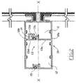
- Referring firstly to Fig.3 there is shown in section a
structural element 20 for a curtain wall. Thestructural element 20 is of a type of which a plurality are adapted to be fixed horizontally and vertically to form a framework for supporting large glass panels or windows that form the major part of the area of the surface wall. In Fig.3 thestructural element 20 is shown at the junction of twoglass panels 21 each of which comprise double-glazing units having inner and outer panels ofglass 21a,21b separated byspacer elements 22, and with asealant 23 being provided between theglass panels 21 and thestructural element 20. It will be understood, however, that the nature of the glass panels and the manner in which they are fixed to the structural element do not form part of this invention and can be of any conventional form. -
Structural element 20 is in the form of an elongate tubular member formed of a suitably strong lightweight material such as extruded aluminium.Structural element 20 is formed from two half-profiles structural elements glass panels 21. Relative to this axis X-X each half-element long section end section long sections glass panels 21, and glass engaging and supportingparts 30c,31c that form an L-shape that engage and support theglass panels 21, with thesealant 23 being provided therebetween. The manner in which the two half-structural elements structural elements structural element 20, that is to say one connection is made between the engaging and supportingparts 30c,31c at the end adjacent theglass panels 21, and the other connection is made at the opposite end of thestructural element 20 between theend sections element elastomeric gasket member shaped member 42 that engages acorresponding slot 43 formed on each half-element. Onegasket member 40 is formed with atongue 45, and the other is formed with acorresponding groove 46 which receivestongue 45. It will be understood, however, that the precise structure of the seal is not critical to the working of this invention. - Notwithstanding the fact that these connections are designed to be watertight, the possibility remains that under extreme weather conditions such as a typhoon or tropical storm rain be driven through the seals provided at the opposed ends of the
structural member 20. Therefore, to provide additional protection against water ingress, the half-elements chamber defining members Transverse members structural member 20 in a direction at right angles to the axis X-X and divide the interior of thestructural member 20 into a number of chambers along the X-X axis. - In the embodiment of Fig.3 half-
element 30 is provided with twotransverse members 30d that extend across the width of thestructural member 20 and are connected to the opposite half-element 31 through a sealing means shown in more detail in Fig.5. Anelastomeric gasket 60 is secured to the half-element 31 and is formed with a T-shaped member 61 that engages in acorresponding locking groove 62 formed in an expandedwidth portion 63 of thetransverse member 30d. Between the twotransverse members 30d is located a similartransverse member 31d formed on the other half-element 31 and which extends towards the first half-element 30 and which is connected to the first half-element 30 with a corresponding seal. The provision of these transverse members has a number of important advantages. - Firstly, the transverse members divide the space of the interior of the
structural member 20 into a number of chambers along the X-X axis. These chambers progressively reduce the air pressure that in extreme weather conditions can cause water to be driven through the seals of existing designs. The number of chambers can be varied. In the embodiment of Fig.3 there are three transverse members defining a total of four chambers, but by varying the number of transverse members the number of chambers can be varied. For effective prevention of water, ingress however there should be at least three chambers, ie at least two transverse members. More chambers are possible however. For example five chambers could be formed by providing four transverse members (two on each half-element). - Secondly, because as one goes along the X-X axis the transverse members extend from opposite sides, ie from alternating half-elements, the seals are provided on alternating sides of the X-X axis. This means firstly that the seals are not provided along the X-X axis itself and so are far less vulnerable to directly wind driven rain, and secondly because the seals alternate from one side of the structural element to the other, any rain that is to pass through these seals must also alternate in direction from one side of the structural element to the other.
- The result is a configuration for the structural element that provides substantially better protection against water ingress (especially from wind driven rain) than existing designs. Further more the design is simple and easy to assemble and does not require the half-elements to be fabricated to abnormally high tolerances.
Claims (6)
- A structural element for a curtain wall, said element comprising two half-elements that are joined together along an axis extending normal to the plane of the wall, said half-elements being interconnected by a plurality of seals, said seals being located on opposing sides of said axis, wherein said element is divided by interconnecting transverse wall members into at least three chambers along the axis.
- A structural element as claimed in claim 1 wherein the seals are provided at the ends of said transverse wall members.
- A structural element as claimed in claim 2 wherein each said transverse wall member extends from one half-element towards the other half-element to which it is connected by a said seal, and wherein said transverse wall members extend from alternating half-elements sequentially along the axis such that said seals alternate between one side of the axis and the other.
- A structural element as claimed in any preceding claim wherein said element is provided with further seals at opposed ends of said element.
- A structural element as claimed in claim 4 wherein said further seals are located on the said axis.
- A structural element for a curtain wall, said element comprising two half-elements that are joined together along an axis extending normal to the plane of the wall, said half-elements being interconnected by a plurality of transverse wall members that divide the interior of said element into at least three chambers along the said axis.
Applications Claiming Priority (2)
| Application Number | Priority Date | Filing Date | Title |
|---|---|---|---|
| CN99101256 | 1999-03-25 | ||
| CN99101256 | 1999-03-25 |
Publications (2)
| Publication Number | Publication Date |
|---|---|
| EP1039059A2 true EP1039059A2 (en) | 2000-09-27 |
| EP1039059A3 EP1039059A3 (en) | 2001-10-10 |
Family
ID=5270377
Family Applications (1)
| Application Number | Title | Priority Date | Filing Date |
|---|---|---|---|
| EP00301566A Withdrawn EP1039059A3 (en) | 1999-03-25 | 2000-02-28 | Curtain wall element |
Country Status (1)
| Country | Link |
|---|---|
| EP (1) | EP1039059A3 (en) |
Cited By (7)
| Publication number | Priority date | Publication date | Assignee | Title |
|---|---|---|---|---|
| FR2942280A1 (en) * | 2009-02-17 | 2010-08-20 | Profils Systemes | CARPENTRY ASSEMBLY |
| FR2946705A1 (en) * | 2009-06-16 | 2010-12-17 | Profils Systemes | OPTIMIZED JOINERY JOINERY ASSEMBLY |
| CN103015575A (en) * | 2011-09-27 | 2013-04-03 | 苏州金螳螂幕墙有限公司 | Combined upright post |
| CN103291041A (en) * | 2013-05-22 | 2013-09-11 | 广东金刚幕墙工程有限公司 | Unit-type sub-frame integration system of exterior wall panel |
| CN104343201A (en) * | 2014-10-29 | 2015-02-11 | 金刚幕墙集团有限公司 | Double-curved-surface unit type curtain wall system and mounting method thereof |
| CN111075078A (en) * | 2019-12-24 | 2020-04-28 | 江河创建集团股份有限公司 | Special-shaped transverse locking type double-face panel unit curtain wall system and construction method thereof |
| US11668090B2 (en) | 2019-11-11 | 2023-06-06 | A. & D. Prevost Inc. | Window wall system |
Citations (4)
| Publication number | Priority date | Publication date | Assignee | Title |
|---|---|---|---|---|
| GB2127058A (en) * | 1982-08-03 | 1984-04-04 | Yoshida Kogyo Kk | Panel support of a curtain wall |
| US4809475A (en) * | 1985-11-14 | 1989-03-07 | Eltreva Ag | Facade system of metal sections |
| EP0436868A2 (en) * | 1990-01-12 | 1991-07-17 | Reynolds Aluminium Deutschland, Internationale Vertriebsgesellschaft Mbh | Supporting structure for a façade wall |
| EP0591602A1 (en) * | 1992-10-06 | 1994-04-13 | Götz Entwicklungs- Und Lizenz Gmbh | Interior air conditioning equipment |
-
2000
- 2000-02-28 EP EP00301566A patent/EP1039059A3/en not_active Withdrawn
Patent Citations (4)
| Publication number | Priority date | Publication date | Assignee | Title |
|---|---|---|---|---|
| GB2127058A (en) * | 1982-08-03 | 1984-04-04 | Yoshida Kogyo Kk | Panel support of a curtain wall |
| US4809475A (en) * | 1985-11-14 | 1989-03-07 | Eltreva Ag | Facade system of metal sections |
| EP0436868A2 (en) * | 1990-01-12 | 1991-07-17 | Reynolds Aluminium Deutschland, Internationale Vertriebsgesellschaft Mbh | Supporting structure for a façade wall |
| EP0591602A1 (en) * | 1992-10-06 | 1994-04-13 | Götz Entwicklungs- Und Lizenz Gmbh | Interior air conditioning equipment |
Cited By (11)
| Publication number | Priority date | Publication date | Assignee | Title |
|---|---|---|---|---|
| FR2942280A1 (en) * | 2009-02-17 | 2010-08-20 | Profils Systemes | CARPENTRY ASSEMBLY |
| EP2226442A1 (en) * | 2009-02-17 | 2010-09-08 | Profils Systèmes | Profile assembly of the type rigid coupling |
| FR2946705A1 (en) * | 2009-06-16 | 2010-12-17 | Profils Systemes | OPTIMIZED JOINERY JOINERY ASSEMBLY |
| EP2275611A1 (en) * | 2009-06-16 | 2011-01-19 | Profils Systèmes | Woodwork assembly with optimised seal |
| CN103015575A (en) * | 2011-09-27 | 2013-04-03 | 苏州金螳螂幕墙有限公司 | Combined upright post |
| CN103291041A (en) * | 2013-05-22 | 2013-09-11 | 广东金刚幕墙工程有限公司 | Unit-type sub-frame integration system of exterior wall panel |
| CN103291041B (en) * | 2013-05-22 | 2015-05-06 | 金刚幕墙集团有限公司 | Unit-type sub-frame integration system of exterior wall panel |
| CN104343201A (en) * | 2014-10-29 | 2015-02-11 | 金刚幕墙集团有限公司 | Double-curved-surface unit type curtain wall system and mounting method thereof |
| US11668090B2 (en) | 2019-11-11 | 2023-06-06 | A. & D. Prevost Inc. | Window wall system |
| CN111075078A (en) * | 2019-12-24 | 2020-04-28 | 江河创建集团股份有限公司 | Special-shaped transverse locking type double-face panel unit curtain wall system and construction method thereof |
| CN111075078B (en) * | 2019-12-24 | 2021-06-08 | 江河创建集团股份有限公司 | Special-shaped transverse locking type double-face panel unit curtain wall system and construction method thereof |
Also Published As
| Publication number | Publication date |
|---|---|
| EP1039059A3 (en) | 2001-10-10 |
Similar Documents
| Publication | Publication Date | Title |
|---|---|---|
| US8800221B1 (en) | Vertical and sloped glazing framing members structured for electrical wiring | |
| US7644549B2 (en) | Hybrid window wall/curtain wall system and method of installation | |
| US8898969B2 (en) | Net-zero energy curtain wall | |
| US20170040940A1 (en) | Integrated Solar Energy Curtain Wall System | |
| WO2006094394A1 (en) | Curtain wall system | |
| US20170040929A1 (en) | Integrated Solar Energy Roof System | |
| KR101185026B1 (en) | Steel-aluminium combination type unitized curtain wall | |
| WO1994004765A1 (en) | Stopless butt-joint multiple curtainwall system | |
| GB2137673A (en) | Support structures for walls or roofs | |
| KR101710526B1 (en) | Windows and window frames frame compatible with curtain wall system | |
| CN1452680A (en) | Enhanced curtain wall system | |
| EP1039059A2 (en) | Curtain wall element | |
| LT3059B (en) | Window sashe made of plastics | |
| KR102190764B1 (en) | Curtain Wall Remodeling System and Curtain Wall Remodeling Method Using The Same | |
| CA2860242C (en) | Vertical and sloped glazing framing members structured for electrical wiring | |
| KR102397355B1 (en) | Curtain Wall System Having Ultraviolet Barrier Layer Facing Heat Insulating Part | |
| EP0255808B1 (en) | Glazing system for glass-fronted buildings | |
| US9051732B2 (en) | Intermediate divider within an exterior wall unit | |
| GB2482902A (en) | A Curtain Wall System For Attaching A Variety Of Panels | |
| WO1991018157A1 (en) | Glazed structure system | |
| KR102117407B1 (en) | Panel system for overlapimg outer wall of building and contruction method thereof | |
| DK168338B1 (en) | Modular system for building facades | |
| JP2008184824A (en) | Curtain wall | |
| CN1315605A (en) | Structural members for curtain wall | |
| JPH11287007A (en) | Weathering device of panel unit |
Legal Events
| Date | Code | Title | Description |
|---|---|---|---|
| PUAI | Public reference made under article 153(3) epc to a published international application that has entered the european phase |
Free format text: ORIGINAL CODE: 0009012 |
|
| AK | Designated contracting states |
Kind code of ref document: A2 Designated state(s): AT BE CH CY DE DK ES FI FR GB GR IE IT LI LU MC NL PT SE |
|
| AX | Request for extension of the european patent |
Free format text: AL;LT;LV;MK;RO;SI |
|
| PUAL | Search report despatched |
Free format text: ORIGINAL CODE: 0009013 |
|
| AK | Designated contracting states |
Kind code of ref document: A3 Designated state(s): AT BE CH CY DE DK ES FI FR GB GR IE IT LI LU MC NL PT SE |
|
| AX | Request for extension of the european patent |
Free format text: AL;LT;LV;MK;RO;SI |
|
| AKX | Designation fees paid | ||
| REG | Reference to a national code |
Ref country code: DE Ref legal event code: 8566 |
|
| STAA | Information on the status of an ep patent application or granted ep patent |
Free format text: STATUS: THE APPLICATION IS DEEMED TO BE WITHDRAWN |
|
| 18D | Application deemed to be withdrawn |
Effective date: 20020411 |