EP1038727A1 - Dispositif de correction d'assiette à câblage simplifié pour véhicule automobile - Google Patents
Dispositif de correction d'assiette à câblage simplifié pour véhicule automobile Download PDFInfo
- Publication number
- EP1038727A1 EP1038727A1 EP00400592A EP00400592A EP1038727A1 EP 1038727 A1 EP1038727 A1 EP 1038727A1 EP 00400592 A EP00400592 A EP 00400592A EP 00400592 A EP00400592 A EP 00400592A EP 1038727 A1 EP1038727 A1 EP 1038727A1
- Authority
- EP
- European Patent Office
- Prior art keywords
- sensors
- signal
- sensor
- vehicle
- attitude
- Prior art date
- Legal status (The legal status is an assumption and is not a legal conclusion. Google has not performed a legal analysis and makes no representation as to the accuracy of the status listed.)
- Granted
Links
- 239000004020 conductor Substances 0.000 claims description 15
- 238000005259 measurement Methods 0.000 claims description 4
- 230000005540 biological transmission Effects 0.000 description 5
- 238000010586 diagram Methods 0.000 description 4
- 238000001914 filtration Methods 0.000 description 3
- 239000000470 constituent Substances 0.000 description 2
- 238000009434 installation Methods 0.000 description 2
- 230000003068 static effect Effects 0.000 description 2
- 241000861223 Issus Species 0.000 description 1
- 230000001133 acceleration Effects 0.000 description 1
- 230000000295 complement effect Effects 0.000 description 1
- 238000010276 construction Methods 0.000 description 1
- 230000007547 defect Effects 0.000 description 1
- 238000001514 detection method Methods 0.000 description 1
- 235000021183 entrée Nutrition 0.000 description 1
- 239000007943 implant Substances 0.000 description 1
- 238000012423 maintenance Methods 0.000 description 1
- 239000003607 modifier Substances 0.000 description 1
- 230000002688 persistence Effects 0.000 description 1
- 230000001052 transient effect Effects 0.000 description 1
Images



Classifications
-
- B—PERFORMING OPERATIONS; TRANSPORTING
- B60—VEHICLES IN GENERAL
- B60Q—ARRANGEMENT OF SIGNALLING OR LIGHTING DEVICES, THE MOUNTING OR SUPPORTING THEREOF OR CIRCUITS THEREFOR, FOR VEHICLES IN GENERAL
- B60Q1/00—Arrangement of optical signalling or lighting devices, the mounting or supporting thereof or circuits therefor
- B60Q1/02—Arrangement of optical signalling or lighting devices, the mounting or supporting thereof or circuits therefor the devices being primarily intended to illuminate the way ahead or to illuminate other areas of way or environments
- B60Q1/04—Arrangement of optical signalling or lighting devices, the mounting or supporting thereof or circuits therefor the devices being primarily intended to illuminate the way ahead or to illuminate other areas of way or environments the devices being headlights
- B60Q1/06—Arrangement of optical signalling or lighting devices, the mounting or supporting thereof or circuits therefor the devices being primarily intended to illuminate the way ahead or to illuminate other areas of way or environments the devices being headlights adjustable, e.g. remotely-controlled from inside vehicle
- B60Q1/08—Arrangement of optical signalling or lighting devices, the mounting or supporting thereof or circuits therefor the devices being primarily intended to illuminate the way ahead or to illuminate other areas of way or environments the devices being headlights adjustable, e.g. remotely-controlled from inside vehicle automatically
- B60Q1/10—Arrangement of optical signalling or lighting devices, the mounting or supporting thereof or circuits therefor the devices being primarily intended to illuminate the way ahead or to illuminate other areas of way or environments the devices being headlights adjustable, e.g. remotely-controlled from inside vehicle automatically due to vehicle inclination, e.g. due to load distribution
- B60Q1/115—Arrangement of optical signalling or lighting devices, the mounting or supporting thereof or circuits therefor the devices being primarily intended to illuminate the way ahead or to illuminate other areas of way or environments the devices being headlights adjustable, e.g. remotely-controlled from inside vehicle automatically due to vehicle inclination, e.g. due to load distribution by electric means
-
- B—PERFORMING OPERATIONS; TRANSPORTING
- B60—VEHICLES IN GENERAL
- B60Q—ARRANGEMENT OF SIGNALLING OR LIGHTING DEVICES, THE MOUNTING OR SUPPORTING THEREOF OR CIRCUITS THEREFOR, FOR VEHICLES IN GENERAL
- B60Q2300/00—Indexing codes for automatically adjustable headlamps or automatically dimmable headlamps
- B60Q2300/10—Indexing codes relating to particular vehicle conditions
- B60Q2300/13—Attitude of the vehicle body
- B60Q2300/132—Pitch
Definitions
- the present invention relates to automatic correction devices of attitude, capable of varying the orientation in elevation of the headlights of a vehicle according to the variations of its base.
- Such devices are well known, in particular in the field automobile. They generally use two associated height sensors respectively to the front and rear axles of the vehicle and connected to means of calculation of the vehicle attitude. These attitude calculation means require their turn the orientation of the vehicle headlamp reflectors, which are mounted mobile, so as to adapt the emission direction of the light beams to the trim of the vehicle.
- the object of the invention is to make it possible to produce a correction device orientation of light beams from one or more headlights of a vehicle, especially automobile, in which the number of electrical conductors is reduced.
- Another object of the invention is to further allow the use of sensors standards for the implementation of such devices.
- the invention proposes a device for correcting the orientation of at least one headlamp of a vehicle in particular a motor vehicle as a function of variations in its base, the device comprising at least two sensors capable of each generating an elementary signal, and means of processing of the elementary signals generated by the sensors in order to develop a vehicle attitude information, and at least one actuator associated with a vehicle headlamp to perform beam orientation correction in function of said attitude information, device characterized in that it comprises a single conductor cable connecting the sensors together and a single conductor connecting the sensors to said processing means and applying to the latter a signal combining the elementary signals generated by the sensors.
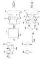
- FIG. 1a there is shown a device for known type of orientation correction of the light beams of the spotlights of a motor vehicle.
- This device includes two height sensors 10a and 10b, associated respectively with the rear and front axles of the vehicle. These sensors deliver respective electrical signals Sa, Sb representative of the distance between their respective axle and the body.
- the signals from sensors 10a and 10b are transmitted via respective electrical conductors 100a and 100b, to a calculation circuit 20 which may include filtering means.
- the circuit 20 determines from these two input signals Sa and Sb and from a center distance information between the axles, information on the attitude of the vehicle, also in the form of an electrical signal S out .
- the signal S out is transmitted via an electrical conductor 100 to two actuators 31 and 32, each integrated in one of the headlights 41, 42 of the vehicle, and which act mechanically on the reflector of their respective headlamp, the amplitude and the direction of movement of the reflectors being a function of the signal S out .
- An additional electrical conductor 110 also connects the circuit calculation 20 to vehicle control means (not shown), to which it delivers a diagnostic signal K on the operation of the device.
- the calculation circuit 20 is in the known embodiment of FIG. 1a located outside the spotlights, and connected by two different conductors 101 and 102 to each of the actuators.
- the two sensors 10a and 10b are generally of PWM output type which modulates the duty cycle of the logic signal sensor output.
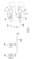
- FIG. 2a the architecture is shown general of a device according to the invention intended for the same function of correction of the orientation of the beams of the two headlights of a motor vehicle.
- elements similar to those already described with reference to Figures 1a and 1b will be referenced in the same way.
- the two sensors 10a and 10b are, as in the known devices, of PWM output type, and measure the respective heights of body above the rear and front axles.
- the sensors themselves are also of known type, as implemented works in existing devices. Each sensor is powered by a source voltage (represented here by the ground and V1 potentials), taken from the vehicle near the sensors and which can correspond to the network voltage of the vehicle.
- a source voltage represented here by the ground and V1 potentials
- An important characteristic of the device according to the invention resides in the fact that the two sensors 10a and 10b are here connected to a single data transmission bus 1000, on which the signals Sa and Sb coming respectively from the sensors 10a and 10b combine to forming the signal S in delivered by the bus 1000 to an attitude calculation circuit 25.
- the downstream part of the architecture of this device is similar to that shown in Figure 1a.
- a respective attitude calculation circuit 251 and 252 inside each of the two headlights 41 and 42 of the vehicle, as shown in FIG. 2b.
- This embodiment of the invention overcomes the questions of installation and support for a calculation circuit external to the projectors.
- two conductors 1001 and 1002 connect the respective circuits 251 and 252 to a point on the bus 1000 located near the projectors.
- the two circuits 251 and 252 then each receive the same signal S in and each deliver the same signal S out to the respective actuator with which they are associated.
- FIG 3 details the structure of sensors 10a and 10b, which each have an open collector output.
- the two sensors 10a and 10b are identical, except for the frequencies of their respective output signals Sa and Sb, which are different.
- the signal Sa has a fixed frequency Fa defining a period Ta and a duty cycle Ra variable, representative of the measurement of sensor 10a, said ratio Ra being in the case of FIG. 4 equal to 50%.
- the signal Sb has a fixed frequency Fb (which is here ten times less than Fa), defining a period Tb and a variable duty cycle Rb representative of the measurement delivered by the sensor 10b, said ratio Rb being in the case of Figure 4 equal to 70%.
- the signal S in is deduced from the duty cycle Ra with accuracy, and the duty ratio Rb with good precision (greater than 10%).
- the rear sensor 10a to the front sensor 10b via a first section of bus transmitting height information from the rear of the vehicle body, the front sensor also being connected to the attitude calculation circuit by a second bus section which transmits the two body height information to the rear and to the front of the vehicle.
- the signal S in transmitted to the calculation circuit can have the appearance shown in FIG. 5: in this figure, the two signals from the two sensors 10a and 10b are here again of the PWM type with two substantially different frequencies Fa and Fb, the two signals Sa and Sb not multiplying but being multiplexed by successively alternating.
- the signals can be of the PWM type or of any other commonly used type.
- the device according to the invention makes it possible to connect two sensors to a single data bus carrying the combination signals from different sensors to one or more calculation circuits of plate. It will be understood that the number of sensors is not limited to two, but that the device can also include additional sensors if necessary connected to the single data transmission bus.
- the configuration according to the invention is particularly advantageous in terms of cost related to wiring and simplicity of installation and maintenance of the device.
- Another advantage of the invention is that the multiplication of signals of substantially different frequencies makes it possible to trace from the combined signal S in each of the individual signals from the respective respective sensors, which facilitates the detection of a fault in one of these sensors.
- the embodiments presented above are intended to be implemented as part of the correction of the orientation of beams of motor vehicle headlamps but do not require the use of specific sensors with a diagnostic line or other components specific. Standard sensors can therefore be used. The only difference between the sensors then lies in the frequencies associated with respective output signals from the device sensors.
- the different frequencies can be fixed once and for all at the construction of the sensor, or even be modifiable thanks to simple means of external connection to sensors.
- the sensors themselves are strictly identical, only the connections made on the elements of different external connections, in order to choose the desired frequency for the sensor.
- FIG. 6 thus schematically represents two sensors supplied each by a source V1 (possibly being the positive voltage of the on-board network of the vehicle). These are the connections made on the housing of each sensor which determine the pulse frequency of the sensor signal Sa, Sb: each sensor 10a, 10b thus comprises a terminal Bx which can be connected either to a source of potential V1, ie to ground. A logic circuit associated with the sensor then fixes the frequency of the output signal Sa, Sb as a function of the potential to which the Bx terminal.
- a first sensor 10a thus delivers a signal Sa at 400 hertz and the second sensor 10b delivers an Sb signal at 50 hertz, these two respective frequencies being particularly well suited to the operation of the correction device according to the invention.
- the device according to the invention also has robustness qualities, because on the one hand the number of connections is reduced by compared to known solutions and secondly the faults of one of the sensors 10a, 10b do not cause the defect of the whole device. It is also possible to apply the invention to any assembly comprising several sensors and requiring a number as few connections as possible between the different components while ensuring the persistence of information from the various sensors in operation when some of the sensors connected to the same transmission bus data is faulty.
Landscapes
- Engineering & Computer Science (AREA)
- Mechanical Engineering (AREA)
- Lighting Device Outwards From Vehicle And Optical Signal (AREA)
Abstract
Description
- correction d'assiette statique, dans laquelle un signal d'assiette instantané fourni par les capteurs est débarrassé de toutes ses composantes transitoires, pour obtenir un signal représentatif seulement de la charge du véhicule,
- correction d'assiette dynamique, dans laquelle il est tenu compte instantanément des variations d'assiette dues notamment aux accélérations, décélérations et virages du véhicule pour modifier en temps réel la hauteur des faisceaux d'éclairage.
- ledit câble conducteur reliant les capteurs entre eux et ledit conducteur reliant les capteurs aux moyens de traitement constituent un bus unique sur lequel les signaux élémentaires sont combinés,
- un premier desdits moyens capteurs transmet son signal élémentaire à un deuxième desdits moyens capteurs auquel sont associés des moyens de combinaison des signaux élémentaires issus des moyens capteurs respectifs, ledit deuxième moyen capteur délivrant en sortie un signal combinant les signaux élémentaires,
- chaque capteur est distinct des moyens de traitement,
- les capteurs délivrent chacun un signal de fréquence fixe et de rapport cyclique variable, représentatif de la mesure délivrée par les capteurs,
- il comporte deux capteurs associés respectivement à un essieu avant et à un essieu arrière du véhicule et le rapport des fréquences des deux capteurs est supérieur à 5,
- le rapport des fréquences des deux capteurs est de l'ordre de 10,
- la fréquence de signal de sortie de chaque capteur est ajustable par des moyens de connectique extérieurs aux capteurs,
- les deux capteurs sont identiques à l'exception de la fréquence de leur signal de sortie,
- la fréquence de signal de sortie de chaque capteur est déterminée en reliant une borne d'entrée du capteur à un potentiel déterminé,
- ledit potentiel déterminé est compris entre les deux valeurs de potentiel qui constituent la tension du réseau de bord du véhicule,
- le signal de sortie de chaque capteur est du type PWM.
- la figure 1a est un schéma de principe d'un dispositif de correction de l'orientation des faisceaux des deux projecteurs d'un véhicule automobile selon un premier mode de réalisation connu,
- la figure 1b est un schéma de principe d'un dispositif de correction selon un deuxième mode de réalisation connu,
- la figure 2a est un schéma de principe d'un premier mode de réalisation selon l'invention d'un dispositif de correction,
- la figure 2b est un schéma de principe d'un deuxième mode de réalisation selon l'invention d'un dispositif de correction,
- la figure 3 est une vue partielle du dispositif de la figure 2b, détaillant certains composants,
- la figure 4 montre l'allure des signaux pouvant être délivrés par chacun des deux capteurs du dispositif selon l'invention, ainsi que la résultante délivrée aux moyens de calcul d'assiette de ce dispositif,
- la figure 5 montre l'allure du signal délivré par les deux capteurs d'une variante du dispositif selon l'invention dans laquelle les capteurs sont montés en série sur un bus unique de transmission de données,
- la figure 6 est une représentation des deux capteurs d'un dispositif selon l'invention, faisant apparaítre des moyens de connectique permettant de différencier les signaux de sortie des capteurs.
Claims (12)
- Dispositif de correction de l'orientation d'au moins un projecteur (41,42) d'un véhicule notamment automobile en fonction des variations d'assiette de celui-ci, le dispositif comprenant au moins deux capteurs (10a, 10b) aptes à engendrer chacun un signal élémentaire (Sa, Sb), des moyens (25, 251, 252) de traitement des signaux élémentaires engendrés par les capteurs afin d'élaborer une information d'assiette du véhicule, et au moins un actionneur (31, 32) associé à un projecteur du véhicule pour effectuer une correction d'orientation de faisceau en fonction de ladite information d'assiette, dispositif caractérisé en ce qu'il comprend un câble conducteur unique (1000) reliant les capteurs entre eux et un conducteur unique (1000) reliant les capteurs auxdits moyens de traitement et appliquant à ces derniers un signal (Sin) combinant les signaux élémentaires (Sa, Sb) engendrés par les capteurs.
- Dispositif selon la revendication 1, caractérisé en ce que ledit câble conducteur reliant les capteurs entre eux et ledit conducteur reliant les capteurs aux moyens de traitement constituent un bus unique (1000) sur lequel les signaux élémentaires (Sa, Sb) sont combinés.
- Dispositif selon la revendication 1, caractérisé en ce qu'un premier desdits moyens capteurs transmet son signal élémentaire à un deuxième desdits moyens capteurs auquel sont associés des moyens de combinaison des signaux élémentaires issus des moyens capteurs respectifs, ledit deuxième moyen capteur délivrant en sortie un signal combinant les signaux élémentaires.
- Dispositif selon l'une des revendications 1 à 3, caractérisé en ce que chaque capteur est distinct des moyens de traitement (25, 251, 252).
- Dispositif selon l'une des revendications 1 à 4, caractérisé en ce que les capteurs (10a, 10b) délivrent chacun un signal (Sa, Sb) de fréquence fixe (Fa, Fb) et de rapport cyclique variable (Ra, Rb), représentatif de la mesure délivrée par les capteurs.
- Dispositif selon la revendication 5, caractérisé en ce qu'il comporte deux capteurs associés respectivement à un essieu avant et à un essieu arrière du véhicule et le rapport (Fa/Fb) des fréquences des deux capteurs est supérieur à 5.
- Dispositif selon la revendication 6, caractérisé en ce que le rapport des fréquences des deux capteurs est de l'ordre de 10.
- Dispositif selon l'une des revendications 5 à 7, caractérisé en ce que la fréquence de signal de sortie de chaque capteur est ajustable par des moyens de connectique extérieurs aux capteurs.
- Dispositif selon la revendication 8, caractérisé en ce que les deux capteurs sont identiques à l'exception de la fréquence de leur signal de sortie.
- Dispositif selon la revendication 8 ou 9, caractérisé en ce que la fréquence de signal de sortie de chaque capteur est déterminée en reliant une borne d'entrée (Bx) du capteur à un potentiel déterminé.
- Dispositif selon la revendication 10, caractérisé en ce que ledit potentiel déterminé est compris entre les deux valeurs de potentiel qui constituent la tension du réseau de bord du véhicule.
- Dispositif selon l'une des revendications précédentes, caractérisé en ce que le signal de sortie de chaque capteur est du type PWM.
Applications Claiming Priority (2)
| Application Number | Priority Date | Filing Date | Title |
|---|---|---|---|
| FR9903662A FR2791307B1 (fr) | 1999-03-24 | 1999-03-24 | Dispositif de correction d'assiette a cablage simplifie pour vehicule automobile |
| FR9903662 | 1999-03-24 |
Publications (2)
| Publication Number | Publication Date |
|---|---|
| EP1038727A1 true EP1038727A1 (fr) | 2000-09-27 |
| EP1038727B1 EP1038727B1 (fr) | 2006-01-04 |
Family
ID=9543576
Family Applications (1)
| Application Number | Title | Priority Date | Filing Date |
|---|---|---|---|
| EP20000400592 Expired - Lifetime EP1038727B1 (fr) | 1999-03-24 | 2000-03-06 | Dispositif de correction d'assiette à câblage simplifié pour véhicule automobile |
Country Status (4)
| Country | Link |
|---|---|
| EP (1) | EP1038727B1 (fr) |
| DE (1) | DE60025319T2 (fr) |
| ES (1) | ES2255952T3 (fr) |
| FR (1) | FR2791307B1 (fr) |
Citations (3)
| Publication number | Priority date | Publication date | Assignee | Title |
|---|---|---|---|---|
| DE3839427A1 (de) * | 1988-11-23 | 1990-05-31 | Vogt Electronic Ag | Automatische leuchtweitenregelung an kfz's |
| EP0430760A1 (fr) * | 1989-11-22 | 1991-06-05 | Valeo Electronique | Dispositif de commande du déplacement d'un organe mobile, notamment pour l'orientation des projecteurs d'éclairage d'un véhicule automobile |
| DE19633482A1 (de) * | 1996-08-20 | 1998-03-05 | Porsche Ag | Leuchteneinheit mit Stellmotor für Fahrzeuge |
-
1999
- 1999-03-24 FR FR9903662A patent/FR2791307B1/fr not_active Expired - Lifetime
-
2000
- 2000-03-06 ES ES00400592T patent/ES2255952T3/es not_active Expired - Lifetime
- 2000-03-06 DE DE2000625319 patent/DE60025319T2/de not_active Expired - Lifetime
- 2000-03-06 EP EP20000400592 patent/EP1038727B1/fr not_active Expired - Lifetime
Patent Citations (3)
| Publication number | Priority date | Publication date | Assignee | Title |
|---|---|---|---|---|
| DE3839427A1 (de) * | 1988-11-23 | 1990-05-31 | Vogt Electronic Ag | Automatische leuchtweitenregelung an kfz's |
| EP0430760A1 (fr) * | 1989-11-22 | 1991-06-05 | Valeo Electronique | Dispositif de commande du déplacement d'un organe mobile, notamment pour l'orientation des projecteurs d'éclairage d'un véhicule automobile |
| DE19633482A1 (de) * | 1996-08-20 | 1998-03-05 | Porsche Ag | Leuchteneinheit mit Stellmotor für Fahrzeuge |
Also Published As
| Publication number | Publication date |
|---|---|
| DE60025319T2 (de) | 2006-09-21 |
| ES2255952T3 (es) | 2006-07-16 |
| FR2791307A1 (fr) | 2000-09-29 |
| DE60025319D1 (de) | 2006-03-30 |
| FR2791307B1 (fr) | 2001-06-08 |
| EP1038727B1 (fr) | 2006-01-04 |
Similar Documents
| Publication | Publication Date | Title |
|---|---|---|
| EP3181991B1 (fr) | Module d'eclairage automobile avec fonctions code et route combinees et une source lumineuse ajustable | |
| CA2985307C (fr) | Vehicule electrique muni d'un reseau de communication | |
| EP3049280B1 (fr) | Dispositif et procédé d'aide à la conduite | |
| FR2723448A1 (fr) | Dispositif de detection d'eau ou analogue sur une glace de vehicule automobile | |
| EP0318354A1 (fr) | Dispositif de transmission d'informations pour véhicule automobile et procédé de mise en oeuvre d'un tel dispositif | |
| FR2843082A1 (fr) | Dispositif de reglage automatique de la position des projecteurs de vehicule automobile | |
| EP1038727B1 (fr) | Dispositif de correction d'assiette à câblage simplifié pour véhicule automobile | |
| EP1195292B1 (fr) | Dispositif de correction d'assiette à câblage simplifié pour véhicule automobile | |
| EP0430760B1 (fr) | Dispositif de commande du déplacement d'un organe mobile, notamment pour l'orientation des projecteurs d'éclairage d'un véhicule automobile | |
| FR3113953A1 (fr) | Unité de réception lidar | |
| WO2010000859A1 (fr) | Ensemble de commutation pour haut de colonne de direction de véhicule automobile, ensemble et procédé de commande correspondants | |
| EP0838895B1 (fr) | Commande d'un moteur électrique pas à pas de véhicule automobile, notamment d'un moteur pas à pas pour la correction d'un projecteur | |
| FR3084032A1 (fr) | Systeme de capteurs mutualises pour vehicule. | |
| FR2696303A1 (fr) | Dispositif de transmission d'informations entre différents organes fonctionnels d'un véhicule automobile. | |
| FR3013884A1 (fr) | Dispositif de generation d'un signal sonore representatif de la dynamique d'un vehicule et induisant une illusion auditive | |
| FR2698833A1 (fr) | Dispositif de correction automatique de l'orientation des projecteurs d'un véhicule automobile lors des variations d'assiette du véhicule. | |
| EP3357753B1 (fr) | Procédé d' aide à la conduite et système d' aide à la conduite | |
| WO2019224461A1 (fr) | Dispositif d'optimisation des circulations des courants et de la compatibilite electromagnetique pour vehicule et vehicule comprenant un tel dispositif | |
| FR3009465A1 (fr) | Dispositif de communication et vehicule automobile comportant un tel dispositif | |
| FR3121217A1 (fr) | Procédé et dispositif de validation d’un paramétrage d’un système de contrôle d’éclairage extérieur d’un véhicule | |
| EP4561863A1 (fr) | Module lumineux pour dispositif d'éclairage d'un véhicule | |
| FR2931616A1 (fr) | Dispositif d'alimentation d'un ensemble de dispositifs d'eclairage. | |
| EP0985578A1 (fr) | Centrale de pilotage des feux d'un vehicule | |
| EP0445003A1 (fr) | Dispositif de surveillance de pneumatiques de roues de véhicules autmobiles | |
| FR3056347A1 (fr) | Unite electronique de commande, dispositif electronique et systeme associes |
Legal Events
| Date | Code | Title | Description |
|---|---|---|---|
| PUAI | Public reference made under article 153(3) epc to a published international application that has entered the european phase |
Free format text: ORIGINAL CODE: 0009012 |
|
| AK | Designated contracting states |
Kind code of ref document: A1 Designated state(s): DE ES GB IT |
|
| AX | Request for extension of the european patent |
Free format text: AL;LT;LV;MK;RO;SI |
|
| 17P | Request for examination filed |
Effective date: 20010213 |
|
| AKX | Designation fees paid |
Free format text: DE ES GB IT |
|
| GRAP | Despatch of communication of intention to grant a patent |
Free format text: ORIGINAL CODE: EPIDOSNIGR1 |
|
| GRAS | Grant fee paid |
Free format text: ORIGINAL CODE: EPIDOSNIGR3 |
|
| GRAA | (expected) grant |
Free format text: ORIGINAL CODE: 0009210 |
|
| AK | Designated contracting states |
Kind code of ref document: B1 Designated state(s): DE ES GB IT |
|
| REG | Reference to a national code |
Ref country code: GB Ref legal event code: FG4D Free format text: NOT ENGLISH |
|
| REF | Corresponds to: |
Ref document number: 60025319 Country of ref document: DE Date of ref document: 20060330 Kind code of ref document: P |
|
| GBT | Gb: translation of ep patent filed (gb section 77(6)(a)/1977) |
Effective date: 20060405 |
|
| REG | Reference to a national code |
Ref country code: ES Ref legal event code: FG2A Ref document number: 2255952 Country of ref document: ES Kind code of ref document: T3 |
|
| PLBE | No opposition filed within time limit |
Free format text: ORIGINAL CODE: 0009261 |
|
| STAA | Information on the status of an ep patent application or granted ep patent |
Free format text: STATUS: NO OPPOSITION FILED WITHIN TIME LIMIT |
|
| 26N | No opposition filed |
Effective date: 20061005 |
|
| PGFP | Annual fee paid to national office [announced via postgrant information from national office to epo] |
Ref country code: GB Payment date: 20180316 Year of fee payment: 19 Ref country code: DE Payment date: 20180309 Year of fee payment: 19 |
|
| PGFP | Annual fee paid to national office [announced via postgrant information from national office to epo] |
Ref country code: IT Payment date: 20180309 Year of fee payment: 19 |
|
| PGFP | Annual fee paid to national office [announced via postgrant information from national office to epo] |
Ref country code: ES Payment date: 20180427 Year of fee payment: 19 |
|
| REG | Reference to a national code |
Ref country code: DE Ref legal event code: R119 Ref document number: 60025319 Country of ref document: DE |
|
| GBPC | Gb: european patent ceased through non-payment of renewal fee |
Effective date: 20190306 |
|
| PG25 | Lapsed in a contracting state [announced via postgrant information from national office to epo] |
Ref country code: DE Free format text: LAPSE BECAUSE OF NON-PAYMENT OF DUE FEES Effective date: 20191001 Ref country code: GB Free format text: LAPSE BECAUSE OF NON-PAYMENT OF DUE FEES Effective date: 20190306 |
|
| PG25 | Lapsed in a contracting state [announced via postgrant information from national office to epo] |
Ref country code: IT Free format text: LAPSE BECAUSE OF NON-PAYMENT OF DUE FEES Effective date: 20190306 |
|
| REG | Reference to a national code |
Ref country code: ES Ref legal event code: FD2A Effective date: 20200724 |
|
| PG25 | Lapsed in a contracting state [announced via postgrant information from national office to epo] |
Ref country code: ES Free format text: LAPSE BECAUSE OF NON-PAYMENT OF DUE FEES Effective date: 20190307 |