EP1038652B1 - Vacuum and pressure tight cooling ventilating device for thermoforming stations - Google Patents
Vacuum and pressure tight cooling ventilating device for thermoforming stations Download PDFInfo
- Publication number
- EP1038652B1 EP1038652B1 EP00101424A EP00101424A EP1038652B1 EP 1038652 B1 EP1038652 B1 EP 1038652B1 EP 00101424 A EP00101424 A EP 00101424A EP 00101424 A EP00101424 A EP 00101424A EP 1038652 B1 EP1038652 B1 EP 1038652B1
- Authority
- EP
- European Patent Office
- Prior art keywords
- thermoforming station
- fan
- bell
- thermoforming
- inlet portion
- Prior art date
- Legal status (The legal status is an assumption and is not a legal conclusion. Google has not performed a legal analysis and makes no representation as to the accuracy of the status listed.)
- Expired - Lifetime
Links
Images

Classifications
-
- B—PERFORMING OPERATIONS; TRANSPORTING
- B29—WORKING OF PLASTICS; WORKING OF SUBSTANCES IN A PLASTIC STATE IN GENERAL
- B29C—SHAPING OR JOINING OF PLASTICS; SHAPING OF MATERIAL IN A PLASTIC STATE, NOT OTHERWISE PROVIDED FOR; AFTER-TREATMENT OF THE SHAPED PRODUCTS, e.g. REPAIRING
- B29C51/00—Shaping by thermoforming, i.e. shaping sheets or sheet like preforms after heating, e.g. shaping sheets in matched moulds or by deep-drawing; Apparatus therefor
- B29C51/26—Component parts, details or accessories; Auxiliary operations
- B29C51/42—Heating or cooling
- B29C51/427—Cooling of the material with a fluid blast
-
- B—PERFORMING OPERATIONS; TRANSPORTING
- B29—WORKING OF PLASTICS; WORKING OF SUBSTANCES IN A PLASTIC STATE IN GENERAL
- B29C—SHAPING OR JOINING OF PLASTICS; SHAPING OF MATERIAL IN A PLASTIC STATE, NOT OTHERWISE PROVIDED FOR; AFTER-TREATMENT OF THE SHAPED PRODUCTS, e.g. REPAIRING
- B29C2791/00—Shaping characteristics in general
- B29C2791/004—Shaping under special conditions
- B29C2791/006—Using vacuum
-
- B—PERFORMING OPERATIONS; TRANSPORTING
- B29—WORKING OF PLASTICS; WORKING OF SUBSTANCES IN A PLASTIC STATE IN GENERAL
- B29C—SHAPING OR JOINING OF PLASTICS; SHAPING OF MATERIAL IN A PLASTIC STATE, NOT OTHERWISE PROVIDED FOR; AFTER-TREATMENT OF THE SHAPED PRODUCTS, e.g. REPAIRING
- B29C51/00—Shaping by thermoforming, i.e. shaping sheets or sheet like preforms after heating, e.g. shaping sheets in matched moulds or by deep-drawing; Apparatus therefor
- B29C51/10—Forming by pressure difference, e.g. vacuum
-
- Y—GENERAL TAGGING OF NEW TECHNOLOGICAL DEVELOPMENTS; GENERAL TAGGING OF CROSS-SECTIONAL TECHNOLOGIES SPANNING OVER SEVERAL SECTIONS OF THE IPC; TECHNICAL SUBJECTS COVERED BY FORMER USPC CROSS-REFERENCE ART COLLECTIONS [XRACs] AND DIGESTS
- Y10—TECHNICAL SUBJECTS COVERED BY FORMER USPC
- Y10S—TECHNICAL SUBJECTS COVERED BY FORMER USPC CROSS-REFERENCE ART COLLECTIONS [XRACs] AND DIGESTS
- Y10S425/00—Plastic article or earthenware shaping or treating: apparatus
- Y10S425/812—Venting
Definitions
- the present invention relates to a thermoforming station with a bell provided with a cover, which can be opened for fast evacuation of the air from the bell, as described in the introductory part of the claim 1.
- thermoforming stations the invention is related to are conventionally provided for molding a sheet-like (or plate or coil-like) plastic material by drawing this material inside a bell assembly arranged at a position opposite to a mold bearing assembly, so as to be closed on the latter.
- thermoforming station the sheet-like plastic material is brought at first to its plasticizing temperature and then it is locked, in a molding position, by closing the mentioned bell assembly against a perimetrical edge of the plastic material.
- the inside of the bell assembly is evacuated to draw the plastic material into the bell assembly, in order to provide said plastic material with a pre-stretched ball configuration.
- the plastic material as molded is allowed to cool, the bell assembly being constantly closed on the mold to hold the plastic material on the mold itself.
- the cooling step represents the most critical processing step since the outer surface of the molded article must be evenly cooled. In fact, if the outer surface would not be properly evenly cooled, it could retain inner stresses which could deform the molded article which would be rejected.
- the cooling step represents the longest operating step of the thermoforming process and, in order to increase the thermoforming process yield it would be indispensable to make the cooling stage as short as possible.
- thermoforming station in order to accelerate the cooling step of the forming process the inventor of the present invention has provided, in an earlier patent application under the priority date of 3 April 1998, and extended in the European patent application EP-0947307, published 6 October 1999, that a thermoforming station be realised provided with a bell comprising a cover, which can be opened for fast evacuation of the air from the bell. As the cover is lifted, a very large air passage opening is formed, which permits fast exchange of the air, and thus fast cooling. Using fans, cooling air is blown into the opened bell.
- a thermoforming station as described in the introductory part of claim 1 is also known from US-A-3 713 765.
- the state of the art furthermore describes devices for sealing the opening of a fan (e.g. the US-A-3396904 or the EP-0255663A2) or for realising a thermoforming station, which can be opened for the cooling phase (e.g. the EP-0365951A2; the first mentioned solution is limited to the application fo a diaphragm closing element on the fan entrance.
- a fan e.g. the US-A-3396904 or the EP-0255663A2
- thermoforming station e.g. the EP-0365951A2
- the first mentioned solution is limited to the application fo a diaphragm closing element on the fan entrance.
- the main object of the present invention is to provide ventilating means specifically designed for aiding air to easily circulate inside the mentioned thermoforming stations.
- thermoforming station according to Claim 1.
- thermoforming station The provision, on the inventive device, of a shutter element arranged outside the thermoforming station, provides the advantage that an air jet can be easily directed and oriented in the thermoforming station.
- said outer shutter element will facilitate the assembling operations, and will reduce the operating noise (since said shutter element will break the air flow) while reducing the size of the device, to allow a desired number of ventilating devices to be easily arranged about the bell assembly.
- the device according to the invention moreover, provides the additional advantage of easily shutting off or closing the ventilating device, and this by the mentioned shutter element operating with a return force directed in the direction of the vacuum formed inside the bell assembly.
- thermoforming station will facilitate the closing of the shutter element, while properly holding it in this closing position.
- the bell assembly evacuation time as well as the cooling time will be reduced to a minimum.
- the cooling time can be reduced, owing to the inventive device, to total time less than 20 seconds, thereby easily overcoming a threshold of 120 cycles/hours as conventionally provided in processes designed for making domestic refrigerators, cells and counter-doors.
- the inventive device further provides a sealing action against a possible air overpressure generated in the thermoforming station for aiding the thermoforming process.
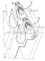
- the cooling ventilating device of the invention has been generally indicated by the reference number 1 in Figure 1.
- Said device comprises a scroll body 2, on the front of which the air outlet 3 has been provided.
- An electric motor 4 for driving the ventilating fan has been moreover provided.
- the ventilating device 1 is provided with a shutter cover 6, which can be driven from an open position (shown by a solid line in Figures 1 and 3) to a closed position ( Figure 2 and dashed in Figure 1).
- the shutter cover or element 6 the shape and size of which have been specifically designed for fully covering the air inlet 5 to the ventilating device 1, is slidably mounted on guides 7, which are in turn mounted between a support 8, on the body side 2 of the ventilating device 1, and a corresponding support 9 opposite to the mentioned support 8.
- the support 9 supports moreover a piston 10-cylinder 11 assembly, which comprises an element 12 for anchoring the piston 10 to the shutter element 6.
- a gasket 13 is moreover provided for air sealing the shutter element 6 on the support 8 (and, accordingly, on the ventilating device body 2, at the level of the air inlet 5 of the latter).
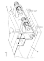
- the above disclosed ventilating device is coupled on the thermoforming station shown in Figures 2 and 3, to form an integrating part of the latter.
- thermoforming station comprises, in particular, a bell assembly 15, having a cover 16 which can be raised and lowered along guiding pins 17 through driving means (not shown).
- the shutter element 6 is brought to its closing position against the air inlet 5 by a displacement in the direction of the arrow F1 of Figure 2.
- This displacement is driven by the piston 10 and is aided by the vacuum formed inside the thermoforming station for thermoforming the sheet material 18 on the mold pattern 19.
- the generated vacuum moreover, will facilitate the abutment and holding of the shutter element 6 on the edge of the air inlet 5 thereby providing an efficient sealing of the latter.
- the cooling ventilating device 1 is driven to cause cooling air to circulate in the direction of the arrows F3 and F4 of Figures 1 and 3.
Abstract
Description
- The present invention relates to a thermoforming station with a bell provided with a cover, which can be opened for fast evacuation of the air from the bell, as described in the introductory part of the
claim 1. - More specifically, the thermoforming stations the invention is related to are conventionally provided for molding a sheet-like (or plate or coil-like) plastic material by drawing this material inside a bell assembly arranged at a position opposite to a mold bearing assembly, so as to be closed on the latter.
- In particular, in such a thermoforming station, the sheet-like plastic material is brought at first to its plasticizing temperature and then it is locked, in a molding position, by closing the mentioned bell assembly against a perimetrical edge of the plastic material.
- Then, the inside of the bell assembly is evacuated to draw the plastic material into the bell assembly, in order to provide said plastic material with a pre-stretched ball configuration.
- Then, a mold is arranged under the thus formed ball, and the vacuum direction is reversed so as to cause the plastic material to be pressed against the mold to receive the desired molded pattern.
- Then, the plastic material as molded is allowed to cool, the bell assembly being constantly closed on the mold to hold the plastic material on the mold itself.
- By the above mentioned molding method a lot of article of manufactures are made, such as bags, car components, cells and counter-doors for domestic refrigerators, bath articles and the like.
- In the above mentioned method, the cooling step represents the most critical processing step since the outer surface of the molded article must be evenly cooled. In fact, if the outer surface would not be properly evenly cooled, it could retain inner stresses which could deform the molded article which would be rejected.
- Moreover, the cooling step represents the longest operating step of the thermoforming process and, in order to increase the thermoforming process yield it would be indispensable to make the cooling stage as short as possible.
- In order to accelerate the cooling step of the forming process the inventor of the present invention has provided, in an earlier patent application under the priority date of 3 April 1998, and extended in the European patent application EP-0947307, published 6 October 1999, that a thermoforming station be realised provided with a bell comprising a cover, which can be opened for fast evacuation of the air from the bell. As the cover is lifted, a very large air passage opening is formed, which permits fast exchange of the air, and thus fast cooling. Using fans, cooling air is blown into the opened bell. A thermoforming station as described in the introductory part of
claim 1 is also known from US-A-3 713 765. - The state of the art furthermore describes devices for sealing the opening of a fan (e.g. the US-A-3396904 or the EP-0255663A2) or for realising a thermoforming station, which can be opened for the cooling phase (e.g. the EP-0365951A2; the first mentioned solution is limited to the application fo a diaphragm closing element on the fan entrance.
- Accordingly, the main object of the present invention is to provide ventilating means specifically designed for aiding air to easily circulate inside the mentioned thermoforming stations.
- According to one aspect of the present invention, the above mentioned object, as well as yet other objects, which will become more apparent hereinafter, are achieved by a thermoforming station according to
Claim 1. - Preferred embodiments of the invention are defined in the dependent claims.
- The provision, on the inventive device, of a shutter element arranged outside the thermoforming station, provides the advantage that an air jet can be easily directed and oriented in the thermoforming station.
- Moreover, said outer shutter element will facilitate the assembling operations, and will reduce the operating noise (since said shutter element will break the air flow) while reducing the size of the device, to allow a desired number of ventilating devices to be easily arranged about the bell assembly.
- The device according to the invention, moreover, provides the additional advantage of easily shutting off or closing the ventilating device, and this by the mentioned shutter element operating with a return force directed in the direction of the vacuum formed inside the bell assembly.
- Thus, the negative pressure formed in the thermoforming station will facilitate the closing of the shutter element, while properly holding it in this closing position.
- Thus, the bell assembly evacuation time as well as the cooling time will be reduced to a minimum. In particular, the cooling time can be reduced, owing to the inventive device, to total time less than 20 seconds, thereby easily overcoming a threshold of 120 cycles/hours as conventionally provided in processes designed for making domestic refrigerators, cells and counter-doors.
- Advantageously, moreover, the inventive device further provides a sealing action against a possible air overpressure generated in the thermoforming station for aiding the thermoforming process.
- The invention will be disclosed hereinafter with reference to the figures of the accompanying drawings, given only by way way of an example of a preferred embodiment of the invention.
- In the drawings:
- Figure 1 illustrates the cooling ventilating device according to the present invention, with the shutter element or body being shown in a longitudinal cross-section;
- Figure 2 is a broken away view illustrating the thermoforming station of the invention, during an evacuating operating step thereof;
and - Figure 3 illustrates the thermoforming station of Figure 2 during a cooling operating step thereof.
- The cooling ventilating device of the invention has been generally indicated by the
reference number 1 in Figure 1. Said device comprises ascroll body 2, on the front of which theair outlet 3 has been provided. - An electric motor 4 for driving the ventilating fan has been moreover provided.
- At the air inlet section 5 to the
body 2, theventilating device 1 is provided with ashutter cover 6, which can be driven from an open position (shown by a solid line in Figures 1 and 3) to a closed position (Figure 2 and dashed in Figure 1). - The shutter cover or
element 6, the shape and size of which have been specifically designed for fully covering the air inlet 5 to theventilating device 1, is slidably mounted on guides 7, which are in turn mounted between asupport 8, on thebody side 2 of theventilating device 1, and acorresponding support 9 opposite to the mentionedsupport 8. - The
support 9 supports moreover a piston 10-cylinder 11 assembly, which comprises anelement 12 for anchoring thepiston 10 to theshutter element 6. - A
gasket 13 is moreover provided for air sealing theshutter element 6 on the support 8 (and, accordingly, on theventilating device body 2, at the level of the air inlet 5 of the latter). - The sliding of the
shutter element 6 on the guides 7, occurring as thepiston 10 is driven, is aided by the provision ofbushings 14. - The above disclosed ventilating device is coupled on the thermoforming station shown in Figures 2 and 3, to form an integrating part of the latter.
- Said thermoforming station comprises, in particular, a
bell assembly 15, having acover 16 which can be raised and lowered along guidingpins 17 through driving means (not shown). - Starting from its open position (shown by the solid line in Figure 1), the
shutter element 6 is brought to its closing position against the air inlet 5 by a displacement in the direction of the arrow F1 of Figure 2. - This displacement is driven by the
piston 10 and is aided by the vacuum formed inside the thermoforming station for thermoforming thesheet material 18 on themold pattern 19. - The generated vacuum, moreover, will facilitate the abutment and holding of the
shutter element 6 on the edge of the air inlet 5 thereby providing an efficient sealing of the latter. - During the cooling operation (Figure 3), as the vacuum is released from the thermoforming station, the
cover 16 of the bell assembly is raised and theshutter element 6 is driven by the cylinder and piston assembly in the direction of the arrow F2. - Then, the
cooling ventilating device 1 is driven to cause cooling air to circulate in the direction of the arrows F3 and F4 of Figures 1 and 3. - The invention, as disclosed and illustrated, is susceptible to several modifications and variations, without departing from the scope of the invention as defined in the accompanying claims.
Claims (7)
- Thermoforming station with a bell (15) provided with a cover (16), which can be opened for fast evacuation of the air from the bell (15) in order to obtain fast cooling of the item formed, and with at least one fan arrangement (1)arranged outside the bell (15), said fan arrangement comprising a fan body having an air inlet portion (5),
characterised in that
said at least one fan arrangement (1) is fixedly mounted to said bell (15) and said inlet portion is provided with means 6) for shutting off said inlet portion (5). - Thermoforming station according to claim 1,
characterised in that
said means (6)for shutting off said inlet portion (5) consist in a shutter cover (6) which can be moved between a position, in which the fan is open, and one in which the fan is closed and sealed to maintain vacuum and pressure. - Thermoforming station accordin to claim 2,
characterised in that
supporting guides (7) are provided for said movable shutter cover (6), which an move towards and away from the air inlet opening (5) of the fan. - Thermoforming station according to claim 3,
characterised in that
support elements (6, 9) are provided taking up said guides (7) on the fan body (2). - Thermoforming station according to claims 3 or 4,
characterised in that
a device with a cylinder (11) and a piston (10) is provided for moving said shutter cover (6). - Thermoforming station according to claim 5,
characterised in that
a sealing gasket (13) is provided on the rim of the sealing cover (5), which rests against said inlet opening plate (8). - Thermoforming station according to claim 1,
characterised in that
two or more fan arrangements are provided for maintaining the thermoforming station below atmospheric pressure, each provided with means of interrupting the air flow, arranged on the air inlet portion of the fan body, which means can be moved simultaneously.
Applications Claiming Priority (2)
| Application Number | Priority Date | Filing Date | Title |
|---|---|---|---|
| ITMI990638 | 1999-03-26 | ||
| IT1999MI000638A IT1312234B1 (en) | 1999-03-26 | 1999-03-26 | VACUUM AND PRESSURE SEAL FAN DEVICE, IN PARTICULAR FOR THERMOFORMING STATIONS, AND THERMOFORMING STATION |
Publications (3)
| Publication Number | Publication Date |
|---|---|
| EP1038652A2 EP1038652A2 (en) | 2000-09-27 |
| EP1038652A3 EP1038652A3 (en) | 2003-01-15 |
| EP1038652B1 true EP1038652B1 (en) | 2006-09-06 |
Family
ID=11382482
Family Applications (1)
| Application Number | Title | Priority Date | Filing Date |
|---|---|---|---|
| EP00101424A Expired - Lifetime EP1038652B1 (en) | 1999-03-26 | 2000-01-25 | Vacuum and pressure tight cooling ventilating device for thermoforming stations |
Country Status (8)
| Country | Link |
|---|---|
| US (1) | US6454556B1 (en) |
| EP (1) | EP1038652B1 (en) |
| AT (1) | ATE338626T1 (en) |
| BR (1) | BR0002047A (en) |
| CA (1) | CA2298726A1 (en) |
| DE (1) | DE60030501T2 (en) |
| ES (1) | ES2272207T3 (en) |
| IT (1) | IT1312234B1 (en) |
Families Citing this family (3)
| Publication number | Priority date | Publication date | Assignee | Title |
|---|---|---|---|---|
| US7708932B2 (en) * | 2006-10-02 | 2010-05-04 | Ford Global Technologies, Llc | Chilled air pressure box for thermoforming a plastic sheet and a method of thermoforming the same |
| US7963749B1 (en) * | 2006-11-25 | 2011-06-21 | Climatecraft Technologies, Inc. | Fan with variable motor speed and disk type unloading device |
| CN113103648A (en) * | 2021-04-27 | 2021-07-13 | 金溪县金港实业有限公司 | Stamping bonding equipment for producing sports protection pad |
Family Cites Families (11)
| Publication number | Priority date | Publication date | Assignee | Title |
|---|---|---|---|---|
| US2098144A (en) * | 1936-07-20 | 1937-11-02 | Hanus John | Air controlling device for blowers |
| US3396904A (en) * | 1967-03-27 | 1968-08-13 | Jan Air Inc | Adjustable air inlet closure |
| US3625629A (en) * | 1970-06-04 | 1971-12-07 | M K M Corp | Proportional blower |
| US3713765A (en) * | 1970-10-22 | 1973-01-30 | D Rise | Differential pressure thermoforming apparatus for forming large articles such as trailer bodies and boats |
| EP0255663B1 (en) * | 1986-08-04 | 1991-04-10 | Siemens Aktiengesellschaft | Ventilation system for a motor vehicle |
| FR2638117B1 (en) * | 1988-10-24 | 1994-07-29 | Anhydride Carbonique Ind | METHOD AND DEVICE FOR COOLING WORKPIECES OBTAINED BY THERMOFORMING |
| US5217563A (en) * | 1988-12-01 | 1993-06-08 | Bayer Aktiengesellschaft | Apparatus for producing a deep-drawn formed plastic piece |
| US5161941A (en) * | 1990-08-28 | 1992-11-10 | Sinko Kogyo, Co, Ltd. | Actuator assembly for controlling inlet air flow to centrifugal fans |
| DE4141362C2 (en) * | 1991-12-14 | 2002-10-24 | Motoren Ventilatoren Gmbh | Radial blower with throttle device |
| US5620715A (en) * | 1994-02-10 | 1997-04-15 | Penda Corporation | Thermoforming machine with controlled cooling station |
| IT1299023B1 (en) * | 1998-04-03 | 2000-02-07 | Rigo Group S R L | THERMOFORMING STATION WITH RAPID COOLING SYSTEM OF THE MOLD AND THERMOFORMING PROCESS CARRIED OUT WITH THIS |
-
1999
- 1999-03-26 IT IT1999MI000638A patent/IT1312234B1/en active
-
2000
- 2000-01-19 US US09/487,152 patent/US6454556B1/en not_active Expired - Fee Related
- 2000-01-25 DE DE60030501T patent/DE60030501T2/en not_active Expired - Fee Related
- 2000-01-25 AT AT00101424T patent/ATE338626T1/en not_active IP Right Cessation
- 2000-01-25 EP EP00101424A patent/EP1038652B1/en not_active Expired - Lifetime
- 2000-01-25 ES ES00101424T patent/ES2272207T3/en not_active Expired - Lifetime
- 2000-02-16 CA CA002298726A patent/CA2298726A1/en not_active Abandoned
- 2000-02-29 BR BR0002047-8A patent/BR0002047A/en not_active Application Discontinuation
Also Published As
| Publication number | Publication date |
|---|---|
| ATE338626T1 (en) | 2006-09-15 |
| DE60030501T2 (en) | 2007-04-12 |
| EP1038652A2 (en) | 2000-09-27 |
| DE60030501D1 (en) | 2006-10-19 |
| ITMI990638A1 (en) | 2000-09-26 |
| BR0002047A (en) | 2000-11-14 |
| ES2272207T3 (en) | 2007-05-01 |
| IT1312234B1 (en) | 2002-04-09 |
| EP1038652A3 (en) | 2003-01-15 |
| US6454556B1 (en) | 2002-09-24 |
| CA2298726A1 (en) | 2000-09-26 |
Similar Documents
| Publication | Publication Date | Title |
|---|---|---|
| US7600358B2 (en) | Method and packaging machine for packaging a product arranged in a tray | |
| EP0947307B1 (en) | Thermoforming station and method with a quick cooling system for the thermoformed articles | |
| JP4490688B2 (en) | Method and apparatus for molding high impact resistant transparent unstrained polymer material | |
| EP0190384A2 (en) | Apparatus for thermally fixing the formed thermoplastic products | |
| EP1038652B1 (en) | Vacuum and pressure tight cooling ventilating device for thermoforming stations | |
| US4352776A (en) | Apparatus and method for fabricating polycarbonate skylights | |
| US5935511A (en) | Method of forming and removing thin walled plastic articles from a plurality of dies in a thermoforming apparatus | |
| JPS60180816A (en) | Device for manufacturing deep drawing section from thermoplastic and method executed in said device | |
| JP3343154B2 (en) | Molding equipment | |
| JPH09183124A (en) | Tire vulcanizing device having evacuating mechanism and tire vulcanizing method | |
| JPH11138592A (en) | Female die of decoration forming die | |
| JP4309234B2 (en) | Lower mold chase replacement method for mold equipment for vacuum forming | |
| CN113448187B (en) | Composite semiconductor thin film material photoresist removing device | |
| CN219947226U (en) | Frame pressing device of plastic suction forming machine | |
| CN114770903B (en) | Thermoplastic forming die internally tangent to reflecting component die and forming method | |
| CN216544408U (en) | Quick refrigerated rack processing is with injection mold | |
| CN218876205U (en) | Air cooling structure for plastic injection molding | |
| CN218518991U (en) | Novel rubber cooling box | |
| CN218803965U (en) | Rapid cooling's thermoforming equipment | |
| CN218430181U (en) | Car horn cover production is with mould of being convenient for to unload | |
| CN117774216A (en) | Injection molding device for plastic part mold | |
| US6793478B2 (en) | Female vacuum forming apparatus for forming deep draw parts | |
| JP2711512B2 (en) | Head opening / closing type rubber vulcanization vacuum molding machine | |
| KR102032800B1 (en) | Device for manufacturing and keeping molded rubber | |
| US3879166A (en) | Apparatus for heating molding materials |
Legal Events
| Date | Code | Title | Description |
|---|---|---|---|
| PUAI | Public reference made under article 153(3) epc to a published international application that has entered the european phase |
Free format text: ORIGINAL CODE: 0009012 |
|
| AK | Designated contracting states |
Kind code of ref document: A2 Designated state(s): AT BE CH CY DE DK ES FI FR GB GR IE IT LI LU MC NL PT SE |
|
| AX | Request for extension of the european patent |
Free format text: AL;LT;LV;MK;RO;SI |
|
| RAP1 | Party data changed (applicant data changed or rights of an application transferred) |
Owner name: RIGO-GAM S.A. |
|
| PUAL | Search report despatched |
Free format text: ORIGINAL CODE: 0009013 |
|
| AK | Designated contracting states |
Kind code of ref document: A3 Designated state(s): AT BE CH CY DE DK ES FI FR GB GR IE IT LI LU MC NL PT SE |
|
| AX | Request for extension of the european patent |
Free format text: AL;LT;LV;MK;RO;SI |
|
| RIC1 | Information provided on ipc code assigned before grant |
Free format text: 7B 29C 51/42 A, 7F 04D 29/42 B |
|
| 17P | Request for examination filed |
Effective date: 20030703 |
|
| AKX | Designation fees paid |
Designated state(s): AT BE CH CY DE DK ES FI FR GB GR IE IT LI LU MC NL PT SE |
|
| 17Q | First examination report despatched |
Effective date: 20040407 |
|
| GRAP | Despatch of communication of intention to grant a patent |
Free format text: ORIGINAL CODE: EPIDOSNIGR1 |
|
| GRAS | Grant fee paid |
Free format text: ORIGINAL CODE: EPIDOSNIGR3 |
|
| GRAA | (expected) grant |
Free format text: ORIGINAL CODE: 0009210 |
|
| AK | Designated contracting states |
Kind code of ref document: B1 Designated state(s): AT BE CH CY DE DK ES FI FR GB GR IE IT LI LU MC NL PT SE |
|
| PG25 | Lapsed in a contracting state [announced via postgrant information from national office to epo] |
Ref country code: IT Free format text: LAPSE BECAUSE OF FAILURE TO SUBMIT A TRANSLATION OF THE DESCRIPTION OR TO PAY THE FEE WITHIN THE PRE;WARNING: LAPSES OF ITALIAN PATENTS WITH EFFECTIVE DATE BEFORE 2007 MAY HAVE OCCURRED AT ANY TIME BEFORE 2007. THE CORRECT EFFECTIVE DATE MAY BE DIFFERENT FROM THE ONE RECORDED.SCRIBED TIME-LIMIT Effective date: 20060906 Ref country code: AT Free format text: LAPSE BECAUSE OF FAILURE TO SUBMIT A TRANSLATION OF THE DESCRIPTION OR TO PAY THE FEE WITHIN THE PRESCRIBED TIME-LIMIT Effective date: 20060906 Ref country code: LI Free format text: LAPSE BECAUSE OF FAILURE TO SUBMIT A TRANSLATION OF THE DESCRIPTION OR TO PAY THE FEE WITHIN THE PRESCRIBED TIME-LIMIT Effective date: 20060906 Ref country code: NL Free format text: LAPSE BECAUSE OF FAILURE TO SUBMIT A TRANSLATION OF THE DESCRIPTION OR TO PAY THE FEE WITHIN THE PRESCRIBED TIME-LIMIT Effective date: 20060906 Ref country code: FI Free format text: LAPSE BECAUSE OF FAILURE TO SUBMIT A TRANSLATION OF THE DESCRIPTION OR TO PAY THE FEE WITHIN THE PRESCRIBED TIME-LIMIT Effective date: 20060906 Ref country code: BE Free format text: LAPSE BECAUSE OF FAILURE TO SUBMIT A TRANSLATION OF THE DESCRIPTION OR TO PAY THE FEE WITHIN THE PRESCRIBED TIME-LIMIT Effective date: 20060906 Ref country code: CH Free format text: LAPSE BECAUSE OF FAILURE TO SUBMIT A TRANSLATION OF THE DESCRIPTION OR TO PAY THE FEE WITHIN THE PRESCRIBED TIME-LIMIT Effective date: 20060906 |
|
| REG | Reference to a national code |
Ref country code: GB Ref legal event code: FG4D |
|
| REG | Reference to a national code |
Ref country code: CH Ref legal event code: EP |
|
| REG | Reference to a national code |
Ref country code: IE Ref legal event code: FG4D |
|
| REF | Corresponds to: |
Ref document number: 60030501 Country of ref document: DE Date of ref document: 20061019 Kind code of ref document: P |
|
| PG25 | Lapsed in a contracting state [announced via postgrant information from national office to epo] |
Ref country code: SE Free format text: LAPSE BECAUSE OF FAILURE TO SUBMIT A TRANSLATION OF THE DESCRIPTION OR TO PAY THE FEE WITHIN THE PRESCRIBED TIME-LIMIT Effective date: 20061206 Ref country code: DK Free format text: LAPSE BECAUSE OF FAILURE TO SUBMIT A TRANSLATION OF THE DESCRIPTION OR TO PAY THE FEE WITHIN THE PRESCRIBED TIME-LIMIT Effective date: 20061206 |
|
| PG25 | Lapsed in a contracting state [announced via postgrant information from national office to epo] |
Ref country code: IE Free format text: LAPSE BECAUSE OF NON-PAYMENT OF DUE FEES Effective date: 20070125 |
|
| PG25 | Lapsed in a contracting state [announced via postgrant information from national office to epo] |
Ref country code: MC Free format text: LAPSE BECAUSE OF NON-PAYMENT OF DUE FEES Effective date: 20070131 |
|
| PG25 | Lapsed in a contracting state [announced via postgrant information from national office to epo] |
Ref country code: PT Free format text: LAPSE BECAUSE OF FAILURE TO SUBMIT A TRANSLATION OF THE DESCRIPTION OR TO PAY THE FEE WITHIN THE PRESCRIBED TIME-LIMIT Effective date: 20070219 |
|
| NLV1 | Nl: lapsed or annulled due to failure to fulfill the requirements of art. 29p and 29m of the patents act | ||
| ET | Fr: translation filed | ||
| REG | Reference to a national code |
Ref country code: CH Ref legal event code: PL |
|
| REG | Reference to a national code |
Ref country code: ES Ref legal event code: FG2A Ref document number: 2272207 Country of ref document: ES Kind code of ref document: T3 |
|
| PLBE | No opposition filed within time limit |
Free format text: ORIGINAL CODE: 0009261 |
|
| STAA | Information on the status of an ep patent application or granted ep patent |
Free format text: STATUS: NO OPPOSITION FILED WITHIN TIME LIMIT |
|
| 26N | No opposition filed |
Effective date: 20070607 |
|
| REG | Reference to a national code |
Ref country code: ES Ref legal event code: FD2A Effective date: 20070126 |
|
| PG25 | Lapsed in a contracting state [announced via postgrant information from national office to epo] |
Ref country code: GR Free format text: LAPSE BECAUSE OF FAILURE TO SUBMIT A TRANSLATION OF THE DESCRIPTION OR TO PAY THE FEE WITHIN THE PRESCRIBED TIME-LIMIT Effective date: 20061207 |
|
| PG25 | Lapsed in a contracting state [announced via postgrant information from national office to epo] |
Ref country code: ES Free format text: LAPSE BECAUSE OF NON-PAYMENT OF DUE FEES Effective date: 20070126 |
|
| PGFP | Annual fee paid to national office [announced via postgrant information from national office to epo] |
Ref country code: FR Payment date: 20081203 Year of fee payment: 10 |
|
| PGFP | Annual fee paid to national office [announced via postgrant information from national office to epo] |
Ref country code: GB Payment date: 20090121 Year of fee payment: 10 |
|
| PG25 | Lapsed in a contracting state [announced via postgrant information from national office to epo] |
Ref country code: CY Free format text: LAPSE BECAUSE OF FAILURE TO SUBMIT A TRANSLATION OF THE DESCRIPTION OR TO PAY THE FEE WITHIN THE PRESCRIBED TIME-LIMIT Effective date: 20060906 Ref country code: LU Free format text: LAPSE BECAUSE OF NON-PAYMENT OF DUE FEES Effective date: 20070125 |
|
| PGFP | Annual fee paid to national office [announced via postgrant information from national office to epo] |
Ref country code: DE Payment date: 20090331 Year of fee payment: 10 |
|
| GBPC | Gb: european patent ceased through non-payment of renewal fee |
Effective date: 20100125 |
|
| REG | Reference to a national code |
Ref country code: FR Ref legal event code: ST Effective date: 20100930 |
|
| PG25 | Lapsed in a contracting state [announced via postgrant information from national office to epo] |
Ref country code: FR Free format text: LAPSE BECAUSE OF NON-PAYMENT OF DUE FEES Effective date: 20100201 |
|
| PG25 | Lapsed in a contracting state [announced via postgrant information from national office to epo] |
Ref country code: DE Free format text: LAPSE BECAUSE OF NON-PAYMENT OF DUE FEES Effective date: 20100803 |
|
| PG25 | Lapsed in a contracting state [announced via postgrant information from national office to epo] |
Ref country code: GB Free format text: LAPSE BECAUSE OF NON-PAYMENT OF DUE FEES Effective date: 20100125 |