EP1038366B1 - Simulationsverfahren für funkfrequenzszenario in mobilfunksystem und testsytem zur durchführung des verfahrens - Google Patents
Simulationsverfahren für funkfrequenzszenario in mobilfunksystem und testsytem zur durchführung des verfahrens Download PDFInfo
- Publication number
- EP1038366B1 EP1038366B1 EP98961242A EP98961242A EP1038366B1 EP 1038366 B1 EP1038366 B1 EP 1038366B1 EP 98961242 A EP98961242 A EP 98961242A EP 98961242 A EP98961242 A EP 98961242A EP 1038366 B1 EP1038366 B1 EP 1038366B1
- Authority
- EP
- European Patent Office
- Prior art keywords
- replicas
- sim
- radiofrequency
- tab
- digital
- Prior art date
- Legal status (The legal status is an assumption and is not a legal conclusion. Google has not performed a legal analysis and makes no representation as to the accuracy of the status listed.)
- Expired - Lifetime
Links
Images


Classifications
-
- H—ELECTRICITY
- H04—ELECTRIC COMMUNICATION TECHNIQUE
- H04B—TRANSMISSION
- H04B17/00—Monitoring; Testing
- H04B17/20—Monitoring; Testing of receivers
- H04B17/29—Performance testing
Definitions
- the present invention relates to the field of test systems for telecommunication equipment and more in particular to a radiofrequency scenario simulation process in mobile radio environment for the testing of receivers of base transceiver stations with intelligent antennas, and testing system employing said process.
- the use of intelligent antennas commences in the mobile radio environment to render the reutilization of the same carrier frequencies in cells of adjacent clusters less critical. This critical character is particularly evident in high traffic urban environment, where reutilization distances can suffer a considerable reduction due to the reduced dimensions of the cells, often of some hundreds of metres only.
- the use of traditional omnidirectional antennas, or of trisectorial ones, involves high interference problems in these particular environments by isofrequential signals coming from adjacent clusters. This is due to the scarce directivity of the antennas, which consequently involves the transmission of comparatively high power signals by the base transceiver stations (BTS).
- BTS base transceiver stations
- the intelligent array antenna is a directive radiant system, able to concentrate the electromagnetic field in the original estimated direction of the signal transmitted by a generic mobile MS (in all the directions of the azimuth plane), separately for all the mobiles of a cell where the antenna is allocated.
- the antenna is therefore characterized by dynamic radiation diagrams (as many as are the time division carriers assigned to the BTS multiplied by the number of time slots) fit with main lobes of reduced angular opening that follow up the directions of the relevant mobiles, thus avoiding to vainly leak power out of these directions.
- this involves a reduction of the total level of isofrequential interferents and, consequently, of the reutilization distance of the same carriers, and therefore of the dimensions of clusters.
- the intelligent antennas are based on the use of electromagnetic field sensor arrays, each sensor being connected to its own transceiver, and the whole of transceivers to a process module able to duly process the signals received, or transmitted, by the single sensors.
- the receiver acts as "master", that is, it estimates on the azimuth plane the arrival directions of signals of the mobiles in transit in its cell and communicates this information to the transmitter that synthesises the angular openings of the antennas in the above mentioned angular directions, supplying the single sensors with replicas of a same signal, duly phase shifted among them.
- the estimate of the arrival directions of useful signals is a complex operation from the computation point of view. It requires in fact an opportune processing of the module and phase information of more replicas of the radio signal received by the different sensors of the array. Said complexity derives from the fact to distinguish in the signal transduced from the array, the directions of the useful signals from those of relevant interferent signals, that is the isofrequential signals emitted by mobiles transiting in adjacent cluster cells, and the echoes due to the multiple reflections of the useful by obstacles spread over the territory, whose extent and time delay depend on the geographic environment of the cell (urban, suburban, rural environment). This information on the arrival directions is then used by the receiver to perform a spatial filtering of the N signals transduced by the array, in order to filter the useful from the different interferents.
- US Patent No. 5,539,772 is an example of a test equipment designed for verifies the performance of a digital satellite receiver belonging to a mobile terminal unit.
- a geostationary satellite retransmits towards the mobile a phone call received from a satellite ground station, in turn connected to a public telephone network.
- the relevant claim 1 of the citation discloses an Apparatus for verifying performance of a RF receiver, comprising:
- a further independent claim of the same cited prior art is directed to a method for testing the receiver.
- a digital frame including a portion dedicated to reproduce the signal transmitted, via satellite, to a mobile telephone unit is generated. Except for the framed digital signal, the claimed method has the substantial features of the claimed apparatus.
- all the means involved in claim 1 generates a narrow band test signal, which because a mobile telephone unit activates only a telephone call at a time, contrarily to the base station which activates a plurality of simultaneous calls. Accordingly, the signal generated by the test apparatus of the citation is unsuitable to test a base station, where a suitable test signal should be of the multicarrier type.
- a minimal realistic test apparatus is charged to synthesize a useful signal freely displaceable inside a wide radiofrequency band, i.e. the 880-915 MHz for extended GSM, plus one or more co-channel interferent having a presettable direction out of 360°.
- a more versatile apparatus could generate several sets of similar signals at the various frequencies. No suggestion is given in the citation about the design of such a test apparatus.
- a general object of the present invention is to propose a simulation process of radiofrequency scenario for the testing of radio receivers with intelligent array antenna, able to identify the direction of a useful signal from those of isofrequential interferents, irrespective of the fact that a spatial filtering is then made.
- Elective object of the present invention is that to overcome the drawbacks of testing systems for receivers of base transceiver stations of cellular telephone systems of old design, and to propose a radiofrequency scenario simulation process in mobile radio environment for the testing of radio receivers of base transceiver stations with intelligent antennas, of new generation, as much realistic as possible, for the whole typology of signals which can incise on the antenna, that is: the useful signals emitted by several mobiles, the relevant echoes due to multiple reflections, the isofrequential interferents due to the reutilization of the carriers, the echoes of said interferents, the interferents from adjacent channel, the echoes of said interferents.
- the subject process can be used for the simulation of a radiofrequency scenario of any cellular telephone system, characterized by the reutilization of carriers.
- the simulated scenario can be tailored in the way time by time considered more adequate to a particular testing requirement.
- the simulated scenario has dynamic characteristics, obtained varying at pre-set time intervals the setting of parameters relevant to characteristic magnitudes of useful and interferent carriers contained in said tables, which define the simulated scenario, such as for instance: level, delay, arrival direction, etc., the duration of said intervals being rather short to be comparable to the time slot employed by similar variations when occurring in a real scenario, but however sufficient to the reprogramming of the different phases of the simulated scenario.
- the simulation of the scenario includes the presence of noise, the doppler effect due to the speed of mobiles and the quick and sudden fadings of the electromagnetic field received, caused by destructive interference from multiple paths (fading of Rayleigh) or masking by obstacles of different nature encountered by the mobiles.
- further object of the invention is a testing system of receivers of a base station per mobile radio systems with intelligent array antenna, of new generation, employing the scenario simulation process scope of the present invention, as described in claim 11.
- the great advantage that a similar system has, is to enable a complete and accurate testing of the receivers of the above mentioned base station, without the need of preparing sample transmitters on the territory.
- the system is also characterized by an exceptional flexibility in preparing the scenario considered time by time more suitable to the verification of the receiver performance compared to a particular specification standard. In fact, it is sufficient that the testing operator fills in a limited number of tables describing the scenario to simulate, afterwards, simply clicking with the mouse the same become operative in real time.
- a testing system of a device DUT consisting of a simulation equipment SIM_RF connected to a control processor CNTR_PC through a serial bus ET_LAN of a local network, for instance of the Ethernet type, to which also the DUT device is connected.
- the SIM_RF block has N radiofrequency outputs out1, out,2, ..., outN connected, through N coaxial cables, to a same number of inputs in1, in2, ..., inN of the DUT block.
- Relevant radiofrequency signals RF1, RF2, ..., RFN coming out from the SIM_RF block run along said cables, and enter the DUT block.
- Blocks SIM_RF and DUT, as well as the personal computer CNTR_PC, are connected to the serial bus ET_LAN.
- the personal computer CNTR_PC is connected to the ET_LAN bus through its own serial bus SER_PC, the DUT block through a serial bus SER_DUT, and block SIM_RF through M serial buses SER_PR1, SER_PR2, ..., SER_PRM and a M+1-th serial bus SER_LO.
- the SIM_RF block is a simulation equipment governed by the personal computer CNTR_PC
- the DUT block is a receiver of a base transceiver station (BTS) for cellular telephone system of the FDMA/TDMA type, for instance GSM 900 MHz, or DCS 1800 MHz.
- BTS base transceiver station
- the whole of the RF1, ..., RFN signals conforms to the selected standard that defines the radio interface.
- the above mentioned blocks include one or more interface devices towards the local network ET_LAN.
- test bed we can perceive the great advantage offered by the connection in local network both of the testing system CNTR_PC, SIM_RF and of the device to test DUT. In fact, this last could send the results of the different tests directly to the computer CNTR_PC, in a completely asynchronous mode versus the flow of testing data.
- the control processor will avail of evaluation procedures and print of the results, and in the case of variation of input stimulations. In this way the testing will result completely automated.
- the simulation equipment SIM_RF includes M processor modules TX_PROC1, TX_PROC2, ..., TX_PROCM; N broad band radiofrequency transmitters WB_TX1, WB_TX2, ..., WB_TXN; and a LO_CORP block generating N identical signals of local oscillator OL, reaching the transmitters WB_TX1, ..., WB_TXN.
- Each TX_PROC block has N outputs for a same number of digital sequential words Cx y reaching the relevant N parallel buses BS1, BS2, ..., BSN, where the value of index x indicates the origin from a relevant processor module m-th, while the value of index y indicates the n-th bus reached by the signal Cx y .
- I bus BS1, BS2, ..., BSN are connected to an input of relevant broad band transmitters WB_TX1, WB_TX2, ..., WB_TXN identified by the same ordinal number.
- the architecture of the SIM_RF equipment shows a modularity per time division radio carrier, with a maximum of M carriers generated by M modules TX_PROC, and per antenna element, with a maximum of N elements (virtual), supplied by a same number of signals coming out from the WB_TX transmitters.
- Each module TX_PROC generates also the N-1 replicas of its own carrier, duly phase shifted, necessary to control the modularity per antenna element (virtual).
- the processor modules TX_PROC perform the following operations, in a completely digital manner:
- Signals IF1, IF2, ..., IFN reaching the N broad band transmitters WB_TX1, WB_TX2, ..., WB_TXN are converted to analogue by the same, typically compensating the distortion of the senx/x type, broad band filtered, and then converted at radiofrequency in test signals RF1, RF2, ..., RFN placed in a selected transmission sub-band.
- the N signals RF1, RF2, ..., RFN thanks to the beamforming, are suitable to simulate up to M different arrival directions from a unique spatial point. The same directions are in fact recognized by the receiver DUT per intelligent antenna of a BTS in testing phase, and therefore without antenna, on the basis of the reciprocal phase shifting existing between the N carriers of each of the M groups of.
- N isofrequential carriers forming the N broad band signals RF1, RF2, ..., RFN globally conveyed in the DUT block by a same number of coaxial cables.
- Fig.3 highlights with higher circuit detail what already said in the comment of fig.2; in particular it is supplied the architecture of processor modules TX_PROC and of transmitters WB_TX.
- the TX_PROC1 module includes N modulators GMSK1, GMSK2, ..., GMSKN and a INTF_PC block connected, through the serial bus SER_PR1, to the serial bus ET_LAN of the local network to which all the remaining blocks TX_PROC are abutted, the LO_CORP block, as well as the personal computer CNTR_PC and the DUT block highlighted in the testing configuration (test bed) of fig.1.
- digital signals are present, indicated as follows:
- One clock input of GMSK modulators is reached also by a signal CK, used for the generation of relevant and identical digital carriers in base band.
- the N signals C1 1 , C1 2 , ..., C1 N of fig.2 are present; these last reach a first input of relevant N digital adders 1, 2, ..., N, having two inputs, also included in the TX_PROC1 block.
- the second input of said adders is reached by relevant sum signals of corresponding signals Cx y generated by the remaining modules TX_PROC of the block SIM_RF.
- TX_PROC blocks are placed in cascade as for the adders 1 ... N, that is the output of a generic adder of a block reaches an input of the corresponding adder of the block placed downstream.
- adders 1, 2, ..., N of the TX_PROC1 block placed downstream the whole chain of blocks TX_PROC, obtain at output the digital signals at intermediate frequency IF1, IF2, ..., IFN, as cumulative sum of relevant signals Cx y corresponding to those indicated on buses BS1, BS2, ..., BSN of fig.2. It results that the implementation of these last is actually obtained through the M groups of adders 1, 2, ..., N placed in cascade.
- the N digital signals at intermediate frequency IF1, IF2, ..., IFN reach a same number of digital/analogue converters included in the relevant blocks WB_TX1, WB_TX2, ..., WB_TXN.
- Converted signals are duly broad band filtered, amplified, and sent to a first input of relevant mixers MX1, MX2, ..., MXN, reached also by the N identical signals of local oscillator OL coming from LO_CORP, obtaining at output N radiofrequency signals.
- These last are duly filtered and sent to relevant power amplifiers PA1, PA2, ..., PAN, obtaining the N signals RF1, RF2, ..., RFN present at the outputs out1, out2, ..., outN of SIM_RF.
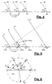
- the antenna has a plane form, whose trace on the figure plane corresponds to the sensors junction line.
- the antenna plane is stricken by two plane waves p1 and p2 coming from two different directions, indicated with two straight lines, perpendicular to the relevant wave fronts and forming two relevant arrival angles ⁇ and ⁇ with the trace of the antenna plane.
- fig.6 a vectorial representation on plane I, Q of the modulated carriers s1(t), s2(t), ..., sN(t) of fig.5 present at the input of the single sensors a1, a2, a3, ..., aN, indicating the corresponding rotating vectors con S 1 , S 2 , S 3 , ..., S N .
- the N pairs of values I and Q so obtained correspond to beamforming coefficients SIM_BEAM_W1, SIM_BEAM_W2, whereas SIM_BEAM_WN of fig.3.
- the mathematical process described above must be repeated for the calculation of beamforming coefficients of the carrier p2; in general, M procedure for each one of the M modulated carriers, generated by the SIM_RF equipment have to be made.
- messages are automatically prepared by the processor CNTR_PC, after the testing operator has filled in a limited number of predetermined tables TAB.1, TAB.2, ..., TAB.K, which summarize the general data describing the scenario to simulate.
- the selection of data to enter can determine the opening of submenus containing the parameters to select for the option specified.
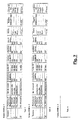
- the tabular display of SIM_RF setting data is made through windows selectable on the screen and connected among them, meaning that the modification of one or more data will affect in real time all the windows involved in said data. Clicking with the mouse, the operator opens a list of possible selectable values, for each case of the table. The operator can retrieve the tables at any moment during the testing and the possible updatings are operational in real time.
- the BTS controls the radio interface monitoring the following parameters (updated every 480 ms):
- the option "FADING: YES” determines the opening of a submenu for the selection of one of the following known propagation models: PROPAGATION MODEL IDENTIFICATION rural area RAx (6 taps) hilly terrain HTX (12 taps) reduced hilly terrain HTx (6 taps) urban area TUx (12 taps) reduced urban area TUx (6 taps) equalization test EQx (6 taps) arbitrary CUSTOM
- any propagation model (excluding CUSTOM) imposes the values of " RF level ", "delay” and "Doppler spectrum type” of the table of fig.7, which determined this choice. Access to the columns of the above mentioned table is therefore inhibited to the operator, and the values automatically included in these columns are those defined by specifications GSM 05.05 Annex C (Propagation conditions). Furthermore, rural area models, reduced hilly terrain, reduced urban area, equalization test automatically engage 6 carriers of SIM_RF; the hilly terrain, urban area models automatically engage 12 carriers of SIM_RF.
- the selection of the discretionary model determines the enabling of the columns “delay” and "Doppler spectrum type” and the engagement of one sole RF carrier, since the selection of the number and characteristics of possible echoes and of the possible (taps) of the model itself is up to the operator.
- the processor CNTR_PC generates the messages instructing the processor modules TX_PROC1, TX_PROC2, ..., TX_PROCM and the block LO_CORP.
- CNTR_PC The necessary procedures to process data supplied by the user and to obtain the information message in the serial format accepted by the network ET_LAN and by interface blocks INTF_PC of the simulation equipment SIM_RF are developed on CNTR_PC. Following is the list of the above mentioned procedures, specifying the procedure input information (inputs) and the information supplied by the procedure itself (outputs). The inputs are the parameters selected by the user and entered through menu and submenus. The outputs contain the messages transferred by CNTR_PC, via bus ET_LAN, to modules TX_PROC and LO_CORP. The procedures performed by CNTR_PC for the generation of the above mentioned messages are the following:
- the contents of all the messages are updated by CNTR_PC at each 4.61 ms GSM frame, and sent according to the same intervals to the concerned units placed in local network, even if the content of a message is unchanged compared to that of the preceding frame. Consequently the concerned modules TX_PROC and LO_CORP, can process in a frame time the updated contents of the relevant messages, in order to be able to change in real time the simulated magnitudes relevant to the modulated carriers sent to the DUT block of fig.1 in the subsequent frame.
- the testing operator confirms the new version that becomes operative in real time, meaning that from that moment on, the messages sent to the network shall be generated starting from the tables of the last version, without stopping for this reason the flow of sequential messages.
- the deriving updating in the content of messages coinciding with the sending of new messages to the network, occurs in synchronous way compared to the frame interval.
- the testing system of fig.1 is very flexible as for the panorama of possible scenarios to simulate, and easy to handle for the testing operator, whose task is limited to the entering of data in the general tables of fig.7.
- SIM_RF which can construct N broad band digital signals at intermediate frequency IF1, ..., IFN, of the multicarrier type.
- Each carrier included in the broad band signals IF1, ..., IFN is characterized by a relevant content of the SIM_NCO message, which established the relevant intermediate frequency; therefore the simulation of several isofrequential interferents engages several modules TX_PROC to which SIM_NCO messages having identical content are sent.
- the simulation system of the example lends itself to some generalizations that configure the invention applicable to other mobile radio systems with system setting different from the FDMA/TDMA one.
- the TDMA aspect is not strictly necessary and, strictly speaking, also the FDMA aspect can be not considered, since for the simulation of a minimum, but realistic scenario, one sole carrier is sufficient with its isofrequential interferents.
- the FDMA/TDMA architecture of the embodiment we must be considered the dynamic characteristic of the simulated scenario which up to now was given by the updating of the significant parameters of the same at 4.61 ms interval of the GSM frame.
- This time slot is a good compromise between the need to avail of a processing time sufficient to the generation of configuration messages of the scenario, to their transfer on local network, and to the programming of the addressee units of the content of the same, and that to be able to simulate a realistic time slot in which the variations indicated by the succession of parameters, correspond to a same variation of the same magnitudes, but referred to phenomena which in the real context comprise the involved carriers.
- Possible applications of the invention in this way could be forecast in the satellite sector.
Landscapes
- Physics & Mathematics (AREA)
- Electromagnetism (AREA)
- Engineering & Computer Science (AREA)
- Computer Networks & Wireless Communication (AREA)
- Signal Processing (AREA)
- Mobile Radio Communication Systems (AREA)
Claims (20)
- Ein Simulationsverfahren für ein Funkfrequenzszenario, insbesondere zum Testen von Empfängern von Basisstationen mit N-elementigen Gruppenantennen für Mobilkommunikation, dadurch gekennzeichnet, dass das Verfahren folgende Schritte enthält:a) Zusammenstellung von allgemeinen Tabellen (TAB.1, TAB.2, ...., TABK) von Parametern und Optionen, die das vorgenannte Funkfrequenzszenario unter Berücksichtigung mindestens eines Nutz-Übertragungssignals und eines oder mehrerer gleichfrequenter Störsignale definieren, wobei sich die simulierten Eintreffrichtungen der Letzteren prinzipiell von der des relevanten vorerwähnten Nutzsignals unterscheiden;b) Umwandlung der vorerwähnten allgemeinen Tabellen in Nachrichten, welche neben anderem Folgendes enthalten: die Beschreibung modulierender Signale (SIM_D) der Übertragungsträger, Nutz- und Störsignale, N komplexe Konstanten (SIM_BEAM_W1, SIM_BEAM_W2, ...., SIM_BEAM_WN) für jede der vorerwähnten simulierten Eintreffrichtungen, erste und zweite Frequenzwerte (SIM_NCO, OL) für die Umsetzungen auf Zwischenfrequenz- und auf Funkfrequenzebene;c) Durchführung von N×P digitalen Modulationen eines Basisbandträgers, wobei ebenso viele GMSK-modulierte Basisbandträger erhalten werden, welche N×P Basisbandkopien bilden (wobei P zwischen 1 und der maximalen Anzahl M von modulierten Trägern (Träger 1, ..., Träger M) gewählt wird, und zwar in der Anzahl passend zu dem vorerwähnten Empfänger (DUT) mit N unabhängigen Eingängen);d) Unterteilung der N×P Basisbandkopien in P Gruppen von N Kopien und Durchführung der ersten N×P digitalen Multiplikationen jeder Basisbandkopie mit einer zu der jeweiligen Gruppe gehörenden komplexen Konstante (SIM_BEAM_W1, SIM_BEAM_W2, ...., SIM_BEAM_WN), wobei der numerische Index der Kopien und die Phasen der Multiplikationskonstanten parallel erhöht werden, um eine Strahlformung jeder der P Gruppen von N Kopien gemäß den vorerwähnten simulierten Eintreffrichtungen zu erreichen;e) Durchführung einer zweiten digitalen Multiplikation jeder strahlgeformten Gruppe von N Kopien mit einem zugehörigen digitalen Zwischenfrequenz-Träger (SIM_NCO), was die Frequenzumsetzung der Gruppe auf die jeweilige Zwischenfrequenz bewirkt, womit dann für jede auf Zwischenfrequenzebene umgesetzte, strahlgeformte Gruppe (C11, C12, ..., C1N; .... ; CM1, CM2, ..., CMN) ihre relative Lage innerhalb des Breitband-Frequenzspektrums des vorerwähnten Empfängers festgelegt wird;f) Mögliche Einstellung des Leistungspegels der vorerwähnten, auf Zwischenfrequenzebene umgesetzte, strahlgeformte Gruppen (C11, C12, ..., C1N; .... ; CM1, CM2, ..., CMN);g) Summierung aller P auf Zwischenfrequenzebene umgesetzten Kopien, die dieselbe numerische Ordnungszahl innerhalb der N Kopien jeder strahlgeformten Gruppe haben, um N Kopien (IF1, IF2, ..., IFN) mit Breitband-Zwischenfrequenzen zu erhalten;h) Analogwandlung der N Kopien (IF1, IF2, ..., IFN) mit Breitband-Zwischenfrequenzen und Breitbandfilterung der analogen Kopien zur Glättung;i) Umsetzung auf Funkfrequenz der geglätteten analogen Kopien, womit N Kopien (RF1, RF2, ..., RFN) mit Breitband-Funkfrequenzen erzeugt werden;j) Leistungsverstärkung und Filterung der N Kopien (RP1, RF2, ..., RFN) mit Breitband-Funkfrequenzen und deren Aufschaltung direkt auf N Funkfrequenzeingänge (in1, in2, ..., inN) des vorerwähnten Empfängers (DUT) unter Umgehung der Antenne, zum Testen der Empfängerfunktion.
- Ein Simulationsverfahren gemäß Anspruch 1, dadurch gekennzeichnet, dass die vorerwähnten allgemeinen Tabellen (TAB.1, TAB.2, ...., TABK) eine zyklisch ausgelesene Folge von K Tabellen bilden.
- Ein Simulationsverfahren gemäß Anspruch 2, dadurch gekennzeichnet, dass die Arbeitsschritte des vorerwähnten Prozesses eine Folge bilden, welche in Zeitintervallen gleicher Dauer wiederholt wird, wobei jedes Mal die vorerwähnten Nachrichten benutzt werden, welche durch Umwandeln einer neuen allgemeinen Tabelle der vorerwähnten zyklischen Folge entstehen, sodass das vorerwähnte simulierte Szenario durch diese Nachrichten dynamische und wiederkehrende Eigenschaften bekommt.
- Ein Simulationsverfahren gemäß Anspruch 3, dadurch gekennzeichnet, dass die vorerwähnte gleiche Dauer der Zeitintervalle so ist, dass die Änderungsgeschwindigkeit der Inhalte der vorerwähnten Nachrichten ähnlich derjenigen ist, die bei den korrespondierenden der vorerwähnten Parameter eines realen Szenarios beobachtet werden kann.
- Ein Simulationsverfahren gemäß Anspruch 4, dadurch gekennzeichnet, dass die vorerwähnte Dauer gleich oder kleiner als 4,61 ms ist.
- Ein Simulationsverfahren gemäß einem beliebigen der Ansprüche 3 bis 5, dadurch gekennzeichnet, dass die vorerwähnten allgemeinen Tabellen (TAB.1, TAB.2, ...., TABK) während der Testzeit aktualisiert werden und dass entsprechend aktualisierte Nachrichten synchron zu den vorerwähnten aufeinander folgenden Zeitintervallen erzeugt werden.
- Ein Simulationsverfahren gemäß Anspruch 3, dadurch gekennzeichnet, dass es einen zusätzlichen Schritt zur Erfassung der Ergebnisse des vorerwähnten Tests enthält, und zwar asynchron zu den vorerwähnten aufeinander folgenden Zeitintervallen.
- Ein Simulationsverfahren gemäß einem beliebigen der vorstehenden Ansprüche, dadurch gekennzeichnet, dass die Wahl mancher der vorerwähnten Optionen vorerwähnter Tabellen (TAB.1, TAB.2, ...., TABK) die Zusammenstellung zugehöriger Untertabellen mit zusätzlichen Parametem beinhaltet, welche für die angegebene Option gewählt werden können.
- Ein Simulationsverfahren gemäß einem beliebigen der Ansprüche 3 bis 8, dadurch gekennzeichnet, dass die vorerwähnten Träger im Zeitmultiplex betrieben werden und dass jedes der vorerwähnten aufeinander folgenden Zeitintervalle gleicher Dauer mit einer Rahmenzeit korrespondiert.
- Ein Simulationsverfahren gemäß einem beliebigen der vorstehenden Ansprüche, dadurch gekennzeichnet, dass die vorerwähnten allgemeinen Tabellen (TAB.1, TAB.2, ...., TABK) außerdem Parameter enthalten, die das Vorhandensein von Rauschen, von Dopplereffekten durch Bewegung der Mobilstationen und von schnellen, plötzlichen Schwundeffekten des elektromagnetischen Feldes am Empfangsort, die entweder durch Interferenzauslöschungen bei Mehrwegeempfang oder durch auf sich bewegende Mobilstationen wirkende Abschattungen verursacht werden, berücksichtigen.
- Ein Testsystem für Empfänger von Basisstationen mit N-elementigen Gruppenantennen für Mobilkommunikation, dadurch gekennzeichnet, dass es Folgendes enthält:einen Steuerprozessor (CNTR_PC) zum Erzeugen von seriellen Nachrichten einschließlich der Beschreibung von Modulationssignalen (SIM_D) mindestens eines Nutzübertragungsträgers und eines oder mehrerer gleichfrequenter Störträger, wobei sich die simulierten Eintreffrichtungen der Letzteren prinzipiell von der des relevanten vorerwähnten Nutzträgers unterscheiden;Interface-Mittel (INTF_PC, LO_CORP) hin zum vorerwähnten Prozessor (CNTR_PC), welche von den besagten Nachrichten mindestens N komplexe Konstanten (SIM_BEAM_W1, SIM_BEAM_W2, ...., SIM_BEAM_WN) für jede der vorerwähnten simulierten Eintreffrichtungen sowie erste und zweite Frequenzwerte (SIM_NCO, OL) für die Umsetzungen auf Zwischenfrequenzebene und auf Funkfrequenzebene empfangen;N×P digitale Modulatoren (GMSK1, GMSK2, ..., GMSKN) für die GMSK-Modulierung eines Basisbandträgers und Erzeugung von GMSK-modulierten Basisbandträgern, die N×P Basisbandkopien bilden (wobei P zwischen 1 und der maximalen Anzahl M von modulierten Trägern (Träger 1, ..., Träger M) gewählt wird), und zwar in der Anzahl passend zu dem vorerwähnten Empfänger (DUT) mit N unabhängigen Eingängen;N×P digitale Modulatoren (GMSK1, GMSK2, ..., GMSKN) zum GMSK-Modulieren eines Basisbandträgers, wobei ebenso viele GMSK-modulierte Basisbandträger erhalten werden, welche N×P Basisbandkopien bilden (wobei P zwischen 1 und der maximalen Anzahl M von modulierten Trägern (Träger 1, ..., Träger M) gewählt wird, und zwar in der Anzahl passend zu dem vorerwähnten Empfänger (DUT) mit N unabhängigen Eingängen)N×P erste digitale Multiplizierer (M1, M2, ..., MN; ...), angeordnet in P Gruppen von N ersten Multiplizierern, zum Multiplizieren jeder Basisbandkopie mit einer zu der jeweiligen Gruppe gehörenden komplexen Konstante (SIM_BEAM_W1, SIM_BEAM_W2, ...., SIM_BEAM_WN), wobei der numerische Index der Kopien und die Phasen der Multiplikationskonstanten parallel erhöht werden, um eine Strahlformung jeder der P Gruppen von N Kopien gemäß den vorerwähnten simulierten Eintreffrichtungen zu erreichen;N×P zweite digitale Multiplizierer (MM1, MM2, ..., MMN; ....), eingeteilt in P Gruppen von N zweiten Multiplizierem, zum Multiplizieren jeder strahlgeformten Gruppe von N Kopien mit einem zugehörigen digitalen Zwischenfrequenz-Träger (SIM_NCO, ....), was die Frequenzumsetzung der Gruppe auf die jeweilige Zwischenfrequenz bewirkt, womit dann für jede auf Zwischenfrequenzebene umgesetzte, strahlgeformte Gruppe (C11, C12, ..., C1N; .... ; CM1, CM2, ..., CMN) ihre relative Lage innerhalb des Breitband-Frequenzspektrums des vorerwähnten Empfängers festgelegt wird;Mittel (CNTR_PC, INTF_PC) zum Einstellen des Leistungspegels der vorerwähnten, auf Zwischenfrequenzebene umgesetzte, strahlgeformte Gruppen (C11, C12, ..., C1N; .... ; CM1, CM2, ..., CMN);N Mittel für digitale Additionen (1, 2, ..., N) zum Summieren aller P auf Zwischenfrequenzebene umgesetzten Kopien, die dieselbe numerische Ordnungszahl innerhalb der N Kopien jeder strahlgeformten Gruppe haben, um N Kopien (IF1, IF2, ..., IFN) mit Breitband-Zwischenfrequenzen zu erhalten;Mittel (D/A) zur Digital/Analog-Umwandlung der vorerwähnten Breitband-Zwischenfrequenz-Kopien (IF1, IF2, ..., IFN), gefolgt von einem Mittel zur Breitbandfilterung zum Glätten der analogen Kopien;N Mittel (MX1, MX2, ..., MXN) zur Funkfrequenzumsetzung, zum Umsetzen der vorerwähnten N geglätteten analogen Kopien (IF1, IF2, ..., IFN) auf Funkfrequenz, wobei N Breitband-Funkfrequenz-Kopien (RF1, RF2, ..., RFN) entstehen;N Funkfrequenz-Leistungsverstärker (PA1, ..., PAN) zum Verstärken des Leistungspegels der vorerwähnten Funkfrequenz-Kopien, die dann in verstärkter Form (RF1, RF2, ..., RFN) zu N Funkfrequenz-Ausgängen (out1, out2, ..., outN) des Testsystems geführt werden, wo die verstärkten Funkfrequenz-Kopien ein einziges Testsignal bilden, das zum Testen der Funktion des vorerwähnten Empfängers geeignet ist;insgesamt N Koaxialkabel oder gleichwertige Mittel, mit denen die vorerwähnten N Funkfrequenz-Ausgänge mit derselben Zahl von Eingängen (in1, in2, ..., inN) des vorerwähnten Empfängers (DUT) ohne Anschluss einer Antenne verbunden werden.
- Ein Testsystem gemäß Anspruch 11, dadurch gekennzeichnet, dass die auf Zwischenfrequenz umgesetzten strahlgeformten Gruppen (C11, C12, ..., C1N; ....; CM1, CM2, ..., CMN) von denen jede aus N Kopien besteht, mittels P identischen, digitalen Modulen (TX_PROC1, ..., TX_PROCM) erzeugt werden, wobei jedes dieser Module eine dedizierte Prozessorschnittstelle (INTF_PC) enthält, die mit N digitalen Modulatoren (GMSK1, GMSK2, ..., GMSKN), N ersten digitalen Multiplizierern (M1, M2, ..., MN) und N zweiten digitalen Multiplizierem (MM1, MM2, ..., MMN) kommuniziert; dabei sind sämtliche digitalen Module mit N Bussen (BS1, BS2, ..., BSN) verbunden, um die N Breitband-Zwischenfrequenz-Kopien (IF1, IF2, ..., IFN) zu ebenso vielen Digital/Analog-Wandlern (D/A) zu übertragen, und zwar über einen Binärbaum aus N Addierern (1, 2, ..., N) mit je zwei Eingängen (1, 2, ..., N).
- Ein Testsystem gemäß Anspruch 11 oder 12, dadurch gekennzeichnet, dass der vorerwähnte Steuerprozessor (CNTR_PC) die vorerwähnten Steuer-Nachrichten (SIM_D, SIM_BEAM_W1, SIM_BEAM_W2, ...., SIM_BEAM_WN SIM_NCO, OL) in aufeinander folgenden Zeitintervallen gleicher Dauer an die vorerwähnten Interface-Mittel (INTF_PC, LO_CORP) überträgt.
- Ein Testsystem gemäß Anspruch 13, dadurch gekennzeichnet, dass die vorerwähnte gleiche Dauer der aufeinander folgenden Zeitintervalle so ist, dass die Änderungsgeschwindigkeit der Inhalte der vorerwähnten Nachrichten ähnlich derjenigen ist, die bei den korrespondierenden der vorerwähnten Parameter eines realen Szenarios beobachtet werden kann.
- Ein Testsystem gemäß einem beliebigen der Ansprüche 11 bis 14, dadurch gekennzeichnet, dass die vorerwähnten Nachrichten durch Umwandlung allgemeiner Tabellen (TAB.1, TAB.2, ...., TABK) von Parametern und Optionen erhalten werden, welche ein simuliertes, im besagten Steuerprozessor (CNTR_PC) gespeichertes Szenario definieren.
- Ein Testsystem gemäß Anspruch 15, dadurch gekennzeichnet, dass die vorerwähnten allgemeinen Tabellen (TAB.1, TAB.2, ...., TABK) eine zyklisch wiederholte Folge von K Tabellen bilden.
- Ein Testsystem gemäß Anspruch 13, dadurch gekennzeichnet, dass die vorerwähnte Dauer gleich oder kleiner als 4,61 ms ist.
- Ein Testsystem gemäß einem beliebigen der Ansprüche 15 bis 17, dadurch gekennzeichnet, dass die vorerwähnten Tabellen (TAB.1, TAB.2, ...., TABK) vor dem Testen ausgefüllt und während des Testens aktualisiert werden und dass die entsprechend aktualisierten Nachrichten synchron zu den vorerwähnten aufeinander folgenden Zeitintervallen erzeugt werden.
- Ein Testsystem gemäß Anspruch 13, dadurch gekennzeichnet, dass die vorerwähnten Träger im Zeitmultiplex betrieben werden und dass die vorerwähnte Dauer mit einer Rahmenzeit korrespondiert.
- Ein Testsystem gemäß einem beliebigen der Ansprüche 15 bis 19, dadurch gekennzeichnet, dass die vorerwähnten allgemeinen Tabellen (TAB.1, TAB.2, ...., TABK) außerdem Parameter enthalten, die das Vorhandensein von Rauschen, von Dopplereffekten durch Bewegung der Mobilstationen und von schnellen, plötzlichen Schwundeffekten des elektromagnetischen Feldes am Empfangsort, die entweder durch Interferenzauslöschungen bei Mehrwegeempfang oder durch auf sich bewegende Mobilstationen wirkende Abschattungen verursacht werden, simulieren.
Applications Claiming Priority (3)
| Application Number | Priority Date | Filing Date | Title |
|---|---|---|---|
| IT97MI002826A IT1296897B1 (it) | 1997-12-19 | 1997-12-19 | Procedimento di simulazione di scenario a radiofrequenza in ambito radiomobile per il collaudo di radioricevitori di stazioni radio base |
| ITMI972826 | 1997-12-19 | ||
| PCT/EP1998/007762 WO1999033202A1 (en) | 1997-12-19 | 1998-11-26 | Simulation process of radiofrequency scenario in radio mobile environment and testing system employing said process |
Publications (2)
| Publication Number | Publication Date |
|---|---|
| EP1038366A1 EP1038366A1 (de) | 2000-09-27 |
| EP1038366B1 true EP1038366B1 (de) | 2003-02-12 |
Family
ID=11378413
Family Applications (1)
| Application Number | Title | Priority Date | Filing Date |
|---|---|---|---|
| EP98961242A Expired - Lifetime EP1038366B1 (de) | 1997-12-19 | 1998-11-26 | Simulationsverfahren für funkfrequenzszenario in mobilfunksystem und testsytem zur durchführung des verfahrens |
Country Status (7)
| Country | Link |
|---|---|
| US (1) | US6993069B1 (de) |
| EP (1) | EP1038366B1 (de) |
| CA (1) | CA2314365C (de) |
| DE (1) | DE69811399T2 (de) |
| ES (1) | ES2191361T3 (de) |
| IT (1) | IT1296897B1 (de) |
| WO (1) | WO1999033202A1 (de) |
Families Citing this family (19)
| Publication number | Priority date | Publication date | Assignee | Title |
|---|---|---|---|---|
| US7162207B2 (en) * | 2004-06-21 | 2007-01-09 | Elektrobit Oy | System, apparatus, method and computer program for producing signals for testing radio frequency communication devices |
| CN100382625C (zh) * | 2004-09-28 | 2008-04-16 | 中兴通讯股份有限公司 | 一种gsm主分集单载频基站自动测试装置 |
| JP3930037B1 (ja) * | 2006-04-27 | 2007-06-13 | 株式会社アドバンテスト | 試験装置および試験方法 |
| EP2140588A4 (de) * | 2007-04-25 | 2015-04-15 | Elektrobit System Test Oy | Simulation eines mehrantennen-funkkanals |
| US8412112B2 (en) * | 2009-05-06 | 2013-04-02 | Ets-Lindgren, L.P. | Systems and methods for simulating a multipath radio frequency environment |
| US8824532B2 (en) * | 2010-03-04 | 2014-09-02 | Apple Inc. | Method and apparatus to generate wireless test signals |
| CN102378232A (zh) * | 2010-08-23 | 2012-03-14 | 财团法人资讯工业策进会 | 无线网络信号的测试系统及其测量方法 |
| JP5351231B2 (ja) * | 2011-10-04 | 2013-11-27 | アンリツ株式会社 | リレーノードシミュレーター及び試験方法 |
| US8744390B2 (en) * | 2012-03-29 | 2014-06-03 | Adc Telecommunications, Inc. | Systems and methods for adjusting system tests based on detected interference |
| CN102932072B (zh) * | 2012-08-08 | 2015-04-15 | 中国传媒大学 | 高动态卫星信道模拟器 |
| KR102207844B1 (ko) * | 2014-07-08 | 2021-01-26 | 한국전자통신연구원 | 적어도 하나의 안테나 배열에 입사하는 신호의 도착 방향을 추정하는 시스템, 방법, 그리고 컴퓨터 판독가능 매체 |
| CN109557827B (zh) * | 2017-09-25 | 2021-10-01 | 中国电力科学研究院 | 一种电网逻辑控制脚本的生成与结果仿真方法及系统 |
| CN108809444A (zh) * | 2018-07-09 | 2018-11-13 | 清华大学 | 利用激波管模拟在等离子鞘套信道下通信性能的实验方法 |
| CN113253090B (zh) * | 2020-02-12 | 2025-12-05 | 罗德施瓦兹两合股份有限公司 | 用于空中测试电子设备的系统和方法 |
| CN111562553A (zh) * | 2020-05-06 | 2020-08-21 | 中国人民解放军63892部队 | 一种提高射频半实物仿真宽带信号角模拟精度的方法 |
| CN114205007B (zh) * | 2021-11-26 | 2024-04-19 | 中电科思仪科技(安徽)有限公司 | 一种基于测试序列的5g终端快速测试系统及方法 |
| CN116781184B (zh) * | 2023-08-18 | 2023-11-07 | 大尧信息科技(湖南)有限公司 | 软件定义的帧突发射频信号模拟方法、介质和系统 |
| WO2025048750A1 (en) * | 2023-08-28 | 2025-03-06 | Aselsan Elektroni̇k Sanayi̇ Ve Ti̇caret Anoni̇m Şi̇rketi̇ | Automatic test system independent of rf peripheral units for digital receivers and technical generators in electronic warfare |
| CN119793926B (zh) * | 2025-01-15 | 2025-09-02 | 启东泽厚智能科技有限公司 | 一种用于试管分拣的自适应识别方法及装置 |
Family Cites Families (10)
| Publication number | Priority date | Publication date | Assignee | Title |
|---|---|---|---|---|
| US5627879A (en) * | 1992-09-17 | 1997-05-06 | Adc Telecommunications, Inc. | Cellular communications system with centralized base stations and distributed antenna units |
| US5539772A (en) * | 1994-10-13 | 1996-07-23 | Westinghouse Electric Corporation | Apparatus and method for verifying performance of RF receiver |
| US5764693A (en) * | 1994-11-14 | 1998-06-09 | Research In Motion Limited | Wireless radio modem with minimal inter-device RF interference |
| JP3304683B2 (ja) * | 1995-05-02 | 2002-07-22 | 富士通株式会社 | 無線装置 |
| US6185259B1 (en) * | 1996-06-12 | 2001-02-06 | Ericsson Inc. | Transmitter/receiver for GMSK and offset-QAM |
| US6018644A (en) * | 1997-01-28 | 2000-01-25 | Northrop Grumman Corporation | Low-loss, fault-tolerant antenna interface unit |
| US6373827B1 (en) * | 1997-10-20 | 2002-04-16 | Wireless Facilities, Inc. | Wireless multimedia carrier system |
| US6025758A (en) * | 1997-10-30 | 2000-02-15 | Uniden San Diego Research & Development Center, Inc. | Method and apparatus for performing digital data signal modulation |
| IT1296896B1 (it) | 1997-12-19 | 1999-08-02 | Italtel Spa | Procedimento di discriminazione di un segnale utile da una pluralita' di interferenti isofrequenziali ricevuti da antenne a schiera di |
| DE102006032669A1 (de) | 2006-07-13 | 2008-01-17 | Günthner, Ewald | Kombispeicher |
-
1997
- 1997-12-19 IT IT97MI002826A patent/IT1296897B1/it active IP Right Grant
-
1998
- 1998-11-26 ES ES98961242T patent/ES2191361T3/es not_active Expired - Lifetime
- 1998-11-26 EP EP98961242A patent/EP1038366B1/de not_active Expired - Lifetime
- 1998-11-26 WO PCT/EP1998/007762 patent/WO1999033202A1/en not_active Ceased
- 1998-11-26 CA CA002314365A patent/CA2314365C/en not_active Expired - Fee Related
- 1998-11-26 US US09/555,809 patent/US6993069B1/en not_active Expired - Fee Related
- 1998-11-26 DE DE69811399T patent/DE69811399T2/de not_active Expired - Fee Related
Also Published As
| Publication number | Publication date |
|---|---|
| US6993069B1 (en) | 2006-01-31 |
| CA2314365A1 (en) | 1999-07-01 |
| IT1296897B1 (it) | 1999-08-02 |
| EP1038366A1 (de) | 2000-09-27 |
| ES2191361T3 (es) | 2003-09-01 |
| DE69811399T2 (de) | 2003-11-27 |
| CA2314365C (en) | 2004-03-02 |
| WO1999033202A1 (en) | 1999-07-01 |
| ITMI972826A1 (it) | 1999-06-19 |
| DE69811399D1 (de) | 2003-03-20 |
Similar Documents
| Publication | Publication Date | Title |
|---|---|---|
| CA2314365C (en) | Simulation process of radiofrequency scenario in radio mobile environment and testing system employing said process | |
| CN112448746B (zh) | 数模混合波束赋形多通道的校正装置方法及装置 | |
| US11025350B2 (en) | Detection and characterisation of passive intermodulation at a MIMO antenna array | |
| CN102904707B (zh) | 用于无线电通信系统的训练序列传输方法 | |
| RU2101870C1 (ru) | Способ передачи модулированных волн, передающее устройство и приемное устройство | |
| US7346316B1 (en) | Radio communication system, a transmitter and a receiver | |
| Hovinen et al. | Ultra wideband indoor radio channel models: Preliminary results | |
| US20110217937A1 (en) | Method and apparatus to generate wireless test signals | |
| US6978131B1 (en) | Testing mobile phones | |
| US20120252366A1 (en) | Wireless signal processor and wireless apparatus | |
| GB2502281A (en) | Detection of Passive Intermodulation Products by simulation and correlation with a received waveform | |
| CN100550673C (zh) | 阵列通信系统接收链路的校准装置及方法 | |
| EP2494720A1 (de) | Funktest | |
| GB2380881A (en) | Estimating the angle of arrival at a mobile terminal | |
| CN112672416A (zh) | 一种无源互调干扰对消中定时同步方法和装置 | |
| EP2659597B1 (de) | Signalverarbeitung für diversitätskombinierenden funkempfänger | |
| US20040048580A1 (en) | Base transceiver station | |
| Bodet et al. | Characterizing sub-THz MIMO channels in practice: A novel channel sounder with absolute time reference | |
| JP3287538B2 (ja) | アダプティブ・アレー受信機 | |
| Moss et al. | A simple model of the UHF cross-polar terrestrial channel for DVBNGH | |
| Wittmann et al. | Impact of the power delay profile shape on the bit error rate in mobile radio systems | |
| CN115396054A (zh) | 一种多径衰落信道模型及其构建方法和应用 | |
| Laspougeas et al. | Radio propagation in urban small cells environment at 2 GHz: experimental spatio-temporal characterization and spatial wideband channel model | |
| Mohr | Wideband propagation measurements of mobile radio channels in mountainous areas in the 1800 MHz frequency range | |
| JP2000206167A (ja) | 無線端末機の電磁界環境特性評価システム |
Legal Events
| Date | Code | Title | Description |
|---|---|---|---|
| PUAI | Public reference made under article 153(3) epc to a published international application that has entered the european phase |
Free format text: ORIGINAL CODE: 0009012 |
|
| 17P | Request for examination filed |
Effective date: 20000627 |
|
| AK | Designated contracting states |
Kind code of ref document: A1 Designated state(s): DE ES FI FR GB IT SE |
|
| GRAG | Despatch of communication of intention to grant |
Free format text: ORIGINAL CODE: EPIDOS AGRA |
|
| GRAG | Despatch of communication of intention to grant |
Free format text: ORIGINAL CODE: EPIDOS AGRA |
|
| GRAH | Despatch of communication of intention to grant a patent |
Free format text: ORIGINAL CODE: EPIDOS IGRA |
|
| 17Q | First examination report despatched |
Effective date: 20020322 |
|
| GRAH | Despatch of communication of intention to grant a patent |
Free format text: ORIGINAL CODE: EPIDOS IGRA |
|
| RAP1 | Party data changed (applicant data changed or rights of an application transferred) |
Owner name: SIEMENS INFORMATION AND COMMUNICATION NETWORKS S.P |
|
| GRAA | (expected) grant |
Free format text: ORIGINAL CODE: 0009210 |
|
| AK | Designated contracting states |
Designated state(s): DE ES FI FR GB IT SE |
|
| REG | Reference to a national code |
Ref country code: GB Ref legal event code: FG4D |
|
| REF | Corresponds to: |
Ref document number: 69811399 Country of ref document: DE Date of ref document: 20030320 Kind code of ref document: P |
|
| RAP2 | Party data changed (patent owner data changed or rights of a patent transferred) |
Owner name: SIEMENS MOBILE COMMUNICATIONS S.P.A. |
|
| REG | Reference to a national code |
Ref country code: SE Ref legal event code: TRGR |
|
| REG | Reference to a national code |
Ref country code: ES Ref legal event code: FG2A Ref document number: 2191361 Country of ref document: ES Kind code of ref document: T3 |
|
| ET | Fr: translation filed | ||
| PLBE | No opposition filed within time limit |
Free format text: ORIGINAL CODE: 0009261 |
|
| STAA | Information on the status of an ep patent application or granted ep patent |
Free format text: STATUS: NO OPPOSITION FILED WITHIN TIME LIMIT |
|
| 26N | No opposition filed |
Effective date: 20031113 |
|
| PGFP | Annual fee paid to national office [announced via postgrant information from national office to epo] |
Ref country code: ES Payment date: 20071129 Year of fee payment: 10 Ref country code: DE Payment date: 20071123 Year of fee payment: 10 |
|
| PGFP | Annual fee paid to national office [announced via postgrant information from national office to epo] |
Ref country code: FI Payment date: 20071115 Year of fee payment: 10 Ref country code: IT Payment date: 20071124 Year of fee payment: 10 |
|
| PGFP | Annual fee paid to national office [announced via postgrant information from national office to epo] |
Ref country code: SE Payment date: 20071114 Year of fee payment: 10 |
|
| PGFP | Annual fee paid to national office [announced via postgrant information from national office to epo] |
Ref country code: GB Payment date: 20071120 Year of fee payment: 10 Ref country code: FR Payment date: 20071122 Year of fee payment: 10 |
|
| EUG | Se: european patent has lapsed | ||
| GBPC | Gb: european patent ceased through non-payment of renewal fee |
Effective date: 20081126 |
|
| PG25 | Lapsed in a contracting state [announced via postgrant information from national office to epo] |
Ref country code: FI Free format text: LAPSE BECAUSE OF NON-PAYMENT OF DUE FEES Effective date: 20081126 |
|
| PG25 | Lapsed in a contracting state [announced via postgrant information from national office to epo] |
Ref country code: IT Free format text: LAPSE BECAUSE OF NON-PAYMENT OF DUE FEES Effective date: 20081126 |
|
| REG | Reference to a national code |
Ref country code: FR Ref legal event code: ST Effective date: 20090731 |
|
| PG25 | Lapsed in a contracting state [announced via postgrant information from national office to epo] |
Ref country code: DE Free format text: LAPSE BECAUSE OF NON-PAYMENT OF DUE FEES Effective date: 20090603 |
|
| PG25 | Lapsed in a contracting state [announced via postgrant information from national office to epo] |
Ref country code: GB Free format text: LAPSE BECAUSE OF NON-PAYMENT OF DUE FEES Effective date: 20081126 |
|
| REG | Reference to a national code |
Ref country code: ES Ref legal event code: FD2A Effective date: 20081127 |
|
| PG25 | Lapsed in a contracting state [announced via postgrant information from national office to epo] |
Ref country code: ES Free format text: LAPSE BECAUSE OF NON-PAYMENT OF DUE FEES Effective date: 20081127 |
|
| PG25 | Lapsed in a contracting state [announced via postgrant information from national office to epo] |
Ref country code: SE Free format text: LAPSE BECAUSE OF NON-PAYMENT OF DUE FEES Effective date: 20081127 |
|
| PG25 | Lapsed in a contracting state [announced via postgrant information from national office to epo] |
Ref country code: FR Free format text: LAPSE BECAUSE OF NON-PAYMENT OF DUE FEES Effective date: 20081130 |