EP1038366B1 - Simulation process of radiofrequency scenario in radio mobile environment and testing system employing said process - Google Patents
Simulation process of radiofrequency scenario in radio mobile environment and testing system employing said process Download PDFInfo
- Publication number
- EP1038366B1 EP1038366B1 EP98961242A EP98961242A EP1038366B1 EP 1038366 B1 EP1038366 B1 EP 1038366B1 EP 98961242 A EP98961242 A EP 98961242A EP 98961242 A EP98961242 A EP 98961242A EP 1038366 B1 EP1038366 B1 EP 1038366B1
- Authority
- EP
- European Patent Office
- Prior art keywords
- replicas
- sim
- radiofrequency
- tab
- digital
- Prior art date
- Legal status (The legal status is an assumption and is not a legal conclusion. Google has not performed a legal analysis and makes no representation as to the accuracy of the status listed.)
- Expired - Lifetime
Links
Images


Classifications
-
- H—ELECTRICITY
- H04—ELECTRIC COMMUNICATION TECHNIQUE
- H04B—TRANSMISSION
- H04B17/00—Monitoring; Testing
- H04B17/20—Monitoring; Testing of receivers
- H04B17/29—Performance testing
Definitions
- the present invention relates to the field of test systems for telecommunication equipment and more in particular to a radiofrequency scenario simulation process in mobile radio environment for the testing of receivers of base transceiver stations with intelligent antennas, and testing system employing said process.
- the use of intelligent antennas commences in the mobile radio environment to render the reutilization of the same carrier frequencies in cells of adjacent clusters less critical. This critical character is particularly evident in high traffic urban environment, where reutilization distances can suffer a considerable reduction due to the reduced dimensions of the cells, often of some hundreds of metres only.
- the use of traditional omnidirectional antennas, or of trisectorial ones, involves high interference problems in these particular environments by isofrequential signals coming from adjacent clusters. This is due to the scarce directivity of the antennas, which consequently involves the transmission of comparatively high power signals by the base transceiver stations (BTS).
- BTS base transceiver stations
- the intelligent array antenna is a directive radiant system, able to concentrate the electromagnetic field in the original estimated direction of the signal transmitted by a generic mobile MS (in all the directions of the azimuth plane), separately for all the mobiles of a cell where the antenna is allocated.
- the antenna is therefore characterized by dynamic radiation diagrams (as many as are the time division carriers assigned to the BTS multiplied by the number of time slots) fit with main lobes of reduced angular opening that follow up the directions of the relevant mobiles, thus avoiding to vainly leak power out of these directions.
- this involves a reduction of the total level of isofrequential interferents and, consequently, of the reutilization distance of the same carriers, and therefore of the dimensions of clusters.
- the intelligent antennas are based on the use of electromagnetic field sensor arrays, each sensor being connected to its own transceiver, and the whole of transceivers to a process module able to duly process the signals received, or transmitted, by the single sensors.
- the receiver acts as "master", that is, it estimates on the azimuth plane the arrival directions of signals of the mobiles in transit in its cell and communicates this information to the transmitter that synthesises the angular openings of the antennas in the above mentioned angular directions, supplying the single sensors with replicas of a same signal, duly phase shifted among them.
- the estimate of the arrival directions of useful signals is a complex operation from the computation point of view. It requires in fact an opportune processing of the module and phase information of more replicas of the radio signal received by the different sensors of the array. Said complexity derives from the fact to distinguish in the signal transduced from the array, the directions of the useful signals from those of relevant interferent signals, that is the isofrequential signals emitted by mobiles transiting in adjacent cluster cells, and the echoes due to the multiple reflections of the useful by obstacles spread over the territory, whose extent and time delay depend on the geographic environment of the cell (urban, suburban, rural environment). This information on the arrival directions is then used by the receiver to perform a spatial filtering of the N signals transduced by the array, in order to filter the useful from the different interferents.
- US Patent No. 5,539,772 is an example of a test equipment designed for verifies the performance of a digital satellite receiver belonging to a mobile terminal unit.
- a geostationary satellite retransmits towards the mobile a phone call received from a satellite ground station, in turn connected to a public telephone network.
- the relevant claim 1 of the citation discloses an Apparatus for verifying performance of a RF receiver, comprising:
- a further independent claim of the same cited prior art is directed to a method for testing the receiver.
- a digital frame including a portion dedicated to reproduce the signal transmitted, via satellite, to a mobile telephone unit is generated. Except for the framed digital signal, the claimed method has the substantial features of the claimed apparatus.
- all the means involved in claim 1 generates a narrow band test signal, which because a mobile telephone unit activates only a telephone call at a time, contrarily to the base station which activates a plurality of simultaneous calls. Accordingly, the signal generated by the test apparatus of the citation is unsuitable to test a base station, where a suitable test signal should be of the multicarrier type.
- a minimal realistic test apparatus is charged to synthesize a useful signal freely displaceable inside a wide radiofrequency band, i.e. the 880-915 MHz for extended GSM, plus one or more co-channel interferent having a presettable direction out of 360°.
- a more versatile apparatus could generate several sets of similar signals at the various frequencies. No suggestion is given in the citation about the design of such a test apparatus.
- a general object of the present invention is to propose a simulation process of radiofrequency scenario for the testing of radio receivers with intelligent array antenna, able to identify the direction of a useful signal from those of isofrequential interferents, irrespective of the fact that a spatial filtering is then made.
- Elective object of the present invention is that to overcome the drawbacks of testing systems for receivers of base transceiver stations of cellular telephone systems of old design, and to propose a radiofrequency scenario simulation process in mobile radio environment for the testing of radio receivers of base transceiver stations with intelligent antennas, of new generation, as much realistic as possible, for the whole typology of signals which can incise on the antenna, that is: the useful signals emitted by several mobiles, the relevant echoes due to multiple reflections, the isofrequential interferents due to the reutilization of the carriers, the echoes of said interferents, the interferents from adjacent channel, the echoes of said interferents.
- the subject process can be used for the simulation of a radiofrequency scenario of any cellular telephone system, characterized by the reutilization of carriers.
- the simulated scenario can be tailored in the way time by time considered more adequate to a particular testing requirement.
- the simulated scenario has dynamic characteristics, obtained varying at pre-set time intervals the setting of parameters relevant to characteristic magnitudes of useful and interferent carriers contained in said tables, which define the simulated scenario, such as for instance: level, delay, arrival direction, etc., the duration of said intervals being rather short to be comparable to the time slot employed by similar variations when occurring in a real scenario, but however sufficient to the reprogramming of the different phases of the simulated scenario.
- the simulation of the scenario includes the presence of noise, the doppler effect due to the speed of mobiles and the quick and sudden fadings of the electromagnetic field received, caused by destructive interference from multiple paths (fading of Rayleigh) or masking by obstacles of different nature encountered by the mobiles.
- further object of the invention is a testing system of receivers of a base station per mobile radio systems with intelligent array antenna, of new generation, employing the scenario simulation process scope of the present invention, as described in claim 11.
- the great advantage that a similar system has, is to enable a complete and accurate testing of the receivers of the above mentioned base station, without the need of preparing sample transmitters on the territory.
- the system is also characterized by an exceptional flexibility in preparing the scenario considered time by time more suitable to the verification of the receiver performance compared to a particular specification standard. In fact, it is sufficient that the testing operator fills in a limited number of tables describing the scenario to simulate, afterwards, simply clicking with the mouse the same become operative in real time.
- a testing system of a device DUT consisting of a simulation equipment SIM_RF connected to a control processor CNTR_PC through a serial bus ET_LAN of a local network, for instance of the Ethernet type, to which also the DUT device is connected.
- the SIM_RF block has N radiofrequency outputs out1, out,2, ..., outN connected, through N coaxial cables, to a same number of inputs in1, in2, ..., inN of the DUT block.
- Relevant radiofrequency signals RF1, RF2, ..., RFN coming out from the SIM_RF block run along said cables, and enter the DUT block.
- Blocks SIM_RF and DUT, as well as the personal computer CNTR_PC, are connected to the serial bus ET_LAN.
- the personal computer CNTR_PC is connected to the ET_LAN bus through its own serial bus SER_PC, the DUT block through a serial bus SER_DUT, and block SIM_RF through M serial buses SER_PR1, SER_PR2, ..., SER_PRM and a M+1-th serial bus SER_LO.
- the SIM_RF block is a simulation equipment governed by the personal computer CNTR_PC
- the DUT block is a receiver of a base transceiver station (BTS) for cellular telephone system of the FDMA/TDMA type, for instance GSM 900 MHz, or DCS 1800 MHz.
- BTS base transceiver station
- the whole of the RF1, ..., RFN signals conforms to the selected standard that defines the radio interface.
- the above mentioned blocks include one or more interface devices towards the local network ET_LAN.
- test bed we can perceive the great advantage offered by the connection in local network both of the testing system CNTR_PC, SIM_RF and of the device to test DUT. In fact, this last could send the results of the different tests directly to the computer CNTR_PC, in a completely asynchronous mode versus the flow of testing data.
- the control processor will avail of evaluation procedures and print of the results, and in the case of variation of input stimulations. In this way the testing will result completely automated.
- the simulation equipment SIM_RF includes M processor modules TX_PROC1, TX_PROC2, ..., TX_PROCM; N broad band radiofrequency transmitters WB_TX1, WB_TX2, ..., WB_TXN; and a LO_CORP block generating N identical signals of local oscillator OL, reaching the transmitters WB_TX1, ..., WB_TXN.
- Each TX_PROC block has N outputs for a same number of digital sequential words Cx y reaching the relevant N parallel buses BS1, BS2, ..., BSN, where the value of index x indicates the origin from a relevant processor module m-th, while the value of index y indicates the n-th bus reached by the signal Cx y .
- I bus BS1, BS2, ..., BSN are connected to an input of relevant broad band transmitters WB_TX1, WB_TX2, ..., WB_TXN identified by the same ordinal number.
- the architecture of the SIM_RF equipment shows a modularity per time division radio carrier, with a maximum of M carriers generated by M modules TX_PROC, and per antenna element, with a maximum of N elements (virtual), supplied by a same number of signals coming out from the WB_TX transmitters.
- Each module TX_PROC generates also the N-1 replicas of its own carrier, duly phase shifted, necessary to control the modularity per antenna element (virtual).
- the processor modules TX_PROC perform the following operations, in a completely digital manner:
- Signals IF1, IF2, ..., IFN reaching the N broad band transmitters WB_TX1, WB_TX2, ..., WB_TXN are converted to analogue by the same, typically compensating the distortion of the senx/x type, broad band filtered, and then converted at radiofrequency in test signals RF1, RF2, ..., RFN placed in a selected transmission sub-band.
- the N signals RF1, RF2, ..., RFN thanks to the beamforming, are suitable to simulate up to M different arrival directions from a unique spatial point. The same directions are in fact recognized by the receiver DUT per intelligent antenna of a BTS in testing phase, and therefore without antenna, on the basis of the reciprocal phase shifting existing between the N carriers of each of the M groups of.
- N isofrequential carriers forming the N broad band signals RF1, RF2, ..., RFN globally conveyed in the DUT block by a same number of coaxial cables.
- Fig.3 highlights with higher circuit detail what already said in the comment of fig.2; in particular it is supplied the architecture of processor modules TX_PROC and of transmitters WB_TX.
- the TX_PROC1 module includes N modulators GMSK1, GMSK2, ..., GMSKN and a INTF_PC block connected, through the serial bus SER_PR1, to the serial bus ET_LAN of the local network to which all the remaining blocks TX_PROC are abutted, the LO_CORP block, as well as the personal computer CNTR_PC and the DUT block highlighted in the testing configuration (test bed) of fig.1.
- digital signals are present, indicated as follows:
- One clock input of GMSK modulators is reached also by a signal CK, used for the generation of relevant and identical digital carriers in base band.
- the N signals C1 1 , C1 2 , ..., C1 N of fig.2 are present; these last reach a first input of relevant N digital adders 1, 2, ..., N, having two inputs, also included in the TX_PROC1 block.
- the second input of said adders is reached by relevant sum signals of corresponding signals Cx y generated by the remaining modules TX_PROC of the block SIM_RF.
- TX_PROC blocks are placed in cascade as for the adders 1 ... N, that is the output of a generic adder of a block reaches an input of the corresponding adder of the block placed downstream.
- adders 1, 2, ..., N of the TX_PROC1 block placed downstream the whole chain of blocks TX_PROC, obtain at output the digital signals at intermediate frequency IF1, IF2, ..., IFN, as cumulative sum of relevant signals Cx y corresponding to those indicated on buses BS1, BS2, ..., BSN of fig.2. It results that the implementation of these last is actually obtained through the M groups of adders 1, 2, ..., N placed in cascade.
- the N digital signals at intermediate frequency IF1, IF2, ..., IFN reach a same number of digital/analogue converters included in the relevant blocks WB_TX1, WB_TX2, ..., WB_TXN.
- Converted signals are duly broad band filtered, amplified, and sent to a first input of relevant mixers MX1, MX2, ..., MXN, reached also by the N identical signals of local oscillator OL coming from LO_CORP, obtaining at output N radiofrequency signals.
- These last are duly filtered and sent to relevant power amplifiers PA1, PA2, ..., PAN, obtaining the N signals RF1, RF2, ..., RFN present at the outputs out1, out2, ..., outN of SIM_RF.
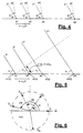
- the antenna has a plane form, whose trace on the figure plane corresponds to the sensors junction line.
- the antenna plane is stricken by two plane waves p1 and p2 coming from two different directions, indicated with two straight lines, perpendicular to the relevant wave fronts and forming two relevant arrival angles ⁇ and ⁇ with the trace of the antenna plane.
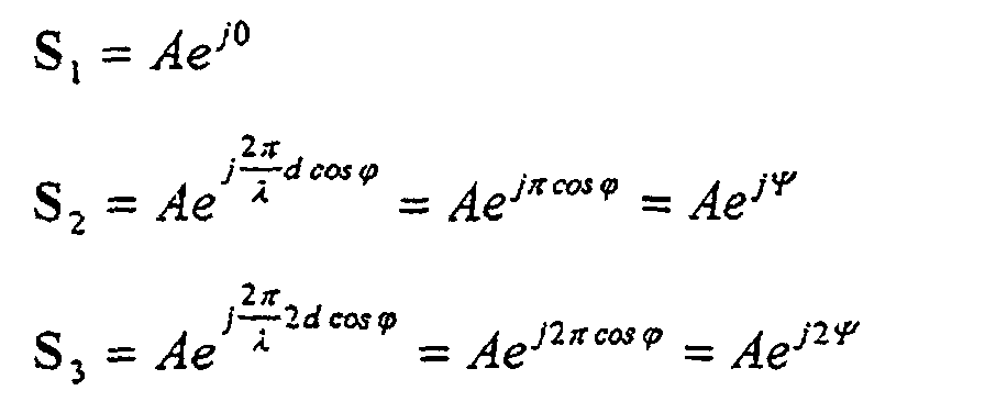
- fig.6 a vectorial representation on plane I, Q of the modulated carriers s1(t), s2(t), ..., sN(t) of fig.5 present at the input of the single sensors a1, a2, a3, ..., aN, indicating the corresponding rotating vectors con S 1 , S 2 , S 3 , ..., S N .
- the N pairs of values I and Q so obtained correspond to beamforming coefficients SIM_BEAM_W1, SIM_BEAM_W2, whereas SIM_BEAM_WN of fig.3.
- the mathematical process described above must be repeated for the calculation of beamforming coefficients of the carrier p2; in general, M procedure for each one of the M modulated carriers, generated by the SIM_RF equipment have to be made.
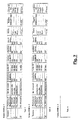
- messages are automatically prepared by the processor CNTR_PC, after the testing operator has filled in a limited number of predetermined tables TAB.1, TAB.2, ..., TAB.K, which summarize the general data describing the scenario to simulate.
- the selection of data to enter can determine the opening of submenus containing the parameters to select for the option specified.
- the tabular display of SIM_RF setting data is made through windows selectable on the screen and connected among them, meaning that the modification of one or more data will affect in real time all the windows involved in said data. Clicking with the mouse, the operator opens a list of possible selectable values, for each case of the table. The operator can retrieve the tables at any moment during the testing and the possible updatings are operational in real time.
- the BTS controls the radio interface monitoring the following parameters (updated every 480 ms):
- the option "FADING: YES” determines the opening of a submenu for the selection of one of the following known propagation models: PROPAGATION MODEL IDENTIFICATION rural area RAx (6 taps) hilly terrain HTX (12 taps) reduced hilly terrain HTx (6 taps) urban area TUx (12 taps) reduced urban area TUx (6 taps) equalization test EQx (6 taps) arbitrary CUSTOM
- any propagation model (excluding CUSTOM) imposes the values of " RF level ", "delay” and "Doppler spectrum type” of the table of fig.7, which determined this choice. Access to the columns of the above mentioned table is therefore inhibited to the operator, and the values automatically included in these columns are those defined by specifications GSM 05.05 Annex C (Propagation conditions). Furthermore, rural area models, reduced hilly terrain, reduced urban area, equalization test automatically engage 6 carriers of SIM_RF; the hilly terrain, urban area models automatically engage 12 carriers of SIM_RF.
- the selection of the discretionary model determines the enabling of the columns “delay” and "Doppler spectrum type” and the engagement of one sole RF carrier, since the selection of the number and characteristics of possible echoes and of the possible (taps) of the model itself is up to the operator.
- the processor CNTR_PC generates the messages instructing the processor modules TX_PROC1, TX_PROC2, ..., TX_PROCM and the block LO_CORP.
- CNTR_PC The necessary procedures to process data supplied by the user and to obtain the information message in the serial format accepted by the network ET_LAN and by interface blocks INTF_PC of the simulation equipment SIM_RF are developed on CNTR_PC. Following is the list of the above mentioned procedures, specifying the procedure input information (inputs) and the information supplied by the procedure itself (outputs). The inputs are the parameters selected by the user and entered through menu and submenus. The outputs contain the messages transferred by CNTR_PC, via bus ET_LAN, to modules TX_PROC and LO_CORP. The procedures performed by CNTR_PC for the generation of the above mentioned messages are the following:
- the contents of all the messages are updated by CNTR_PC at each 4.61 ms GSM frame, and sent according to the same intervals to the concerned units placed in local network, even if the content of a message is unchanged compared to that of the preceding frame. Consequently the concerned modules TX_PROC and LO_CORP, can process in a frame time the updated contents of the relevant messages, in order to be able to change in real time the simulated magnitudes relevant to the modulated carriers sent to the DUT block of fig.1 in the subsequent frame.
- the testing operator confirms the new version that becomes operative in real time, meaning that from that moment on, the messages sent to the network shall be generated starting from the tables of the last version, without stopping for this reason the flow of sequential messages.
- the deriving updating in the content of messages coinciding with the sending of new messages to the network, occurs in synchronous way compared to the frame interval.
- the testing system of fig.1 is very flexible as for the panorama of possible scenarios to simulate, and easy to handle for the testing operator, whose task is limited to the entering of data in the general tables of fig.7.
- SIM_RF which can construct N broad band digital signals at intermediate frequency IF1, ..., IFN, of the multicarrier type.
- Each carrier included in the broad band signals IF1, ..., IFN is characterized by a relevant content of the SIM_NCO message, which established the relevant intermediate frequency; therefore the simulation of several isofrequential interferents engages several modules TX_PROC to which SIM_NCO messages having identical content are sent.
- the simulation system of the example lends itself to some generalizations that configure the invention applicable to other mobile radio systems with system setting different from the FDMA/TDMA one.
- the TDMA aspect is not strictly necessary and, strictly speaking, also the FDMA aspect can be not considered, since for the simulation of a minimum, but realistic scenario, one sole carrier is sufficient with its isofrequential interferents.
- the FDMA/TDMA architecture of the embodiment we must be considered the dynamic characteristic of the simulated scenario which up to now was given by the updating of the significant parameters of the same at 4.61 ms interval of the GSM frame.
- This time slot is a good compromise between the need to avail of a processing time sufficient to the generation of configuration messages of the scenario, to their transfer on local network, and to the programming of the addressee units of the content of the same, and that to be able to simulate a realistic time slot in which the variations indicated by the succession of parameters, correspond to a same variation of the same magnitudes, but referred to phenomena which in the real context comprise the involved carriers.
- Possible applications of the invention in this way could be forecast in the satellite sector.
Landscapes
- Physics & Mathematics (AREA)
- Electromagnetism (AREA)
- Engineering & Computer Science (AREA)
- Computer Networks & Wireless Communication (AREA)
- Signal Processing (AREA)
- Mobile Radio Communication Systems (AREA)
Description
-
EP 0 878 974under the title "Communication Method for cellular telephone systems ", filed on May 16, 1997; - WO 99/33141 under the title "Discrimination process of a useful signal by a plurality of isofrequential interferent signals received by array antennas of base transceiver stations for cellular telecommunication and relevant method".
US Patent No. 5,539,772 is an example of a test equipment designed for verifies the performance of a digital satellite receiver belonging to a mobile terminal unit. As known, a geostationary satellite retransmits towards the mobile a phone call received from a satellite ground station, in turn connected to a public telephone network. The
- arbitrary waveform generator means for outputting an analog in-phase waveform and an analog quadrature waveform in accordance with sampled digital waveform data, said arbitrary waveform generator means including parallel first and second First-In-First-Out random access memories for storing the sampled digital waveform data;
- the sampled digital waveform data comprising an in-phase waveform file stored in said First-In-First-Out memory and a quadrature waveform file stored in said second First-In-First-Out memory
- each of the in-phase and quadrature waveform files including 60% root-cosine differential quadrature phase shift keyed data corresponding to successive frames of primary transmission channel data, co-channel interference data, adjacent channel interference data, and data relating to at least one of a plurality of impairments;
- unity gain reconstruction filter means, connected to said arbitrary waveform generator means, for smoothing the analog in-phase and quadrature, waveforms
- vector signal generator means, responsive to the filtered analog in-phase and quadrature waveforms, for outputting a modulated RF signal; and
- means for coupling an input of the RF receiver to the modulated RF signal output from said vector signal generator.
- fig.1 shows a quite general block diagram of the testing system scope of the present invention, connected to a device to be tested (D.U.T.);
- fig.2 shows more in detail a SIM_RF block of fig.1 belonging to the above mentioned testing system;
- fig.3 shows the SIM_RF block of fig.2 with higher detail, up to the indication of the single circuit blocks;
- fig.4 gives a representation of the directions of plane waves incising on an array antenna, usually employed during the actual operation by the device to be tested (DUT) of fig.1;
- fig.5 shows the progressive phase shifting existing among the components of a plane wave front coming from a direction ϕ of fig.4, on the moment the same incises on the sensors of the array;
- fig.6 shows a picture on the complex I/Q plane of the rotating vectors that represent the components of the plane wave front of fig.5; and
- fig.7 shows the tables previously stored in the permanent storage of the processor of fig.1, available to the testing operator for the setting of the parameters distinguishing a scenario to be simulated.
- acquisition of control signals by the processor CNTR_PC, as serial messages withdrawn from the bus ET_LAN;
- generation of P numeric isofrequential carriers and GMSK modulation of the same using an identical modulating signal, obtaining components in phase I and in quadrature Q of each carrier;
- multiplication of the samples of said components I and Q by relevant complex constants coming from CNTR_PC, originating "weighed" components in phase and module in order to realize beamforming, as we shall see below;
- vectorial sum of I and Q "weighed" components of each carrier, obtaining in change digital modulated carriers GMSK;
- level control of the above mentioned modulated carriers in steps of programmable amplitude;
- control of the ramp-up and ramp-down time of the envelope of the modulated signal, at the beginning and at the end of each burst, respectively (ramp-up and ramp-down functions);
- numeric conversion at intermediate frequency of each modulated carrier, obtaining said digital words Cxy;
- construction of N transmission digital signals of the multicarrier type at intermediate frequency, identified IF1, IF2, ..., IFN, respectively, coinciding with the buses BS1, BS2, ..., BSN, through sum of each m-th word Cxy identified by the same index y.
- SIM_D, BT_SIM, and SIM_DEL directed towards all the GMSK modulators;
- N complex data SIM_BEAM_W1, SIM_BEAM_W2, ....., SIM_BEAM_WN addressed towards an input of relevant first complex digital multipliers M1, M2, ..., MN, the other input of which is reached by the components I and Q coming out from relevant GMSK modulators; and finally
- N identical digital carriers SIM_NCO addressed towards an input of relevant second digital multipliers MM1, MM2, ..., MMN, the other input of which is reached by the signals coming out from relevant first multipliers M1, M2, ..., MN (through the adders of the "weighed" I and Q components, omitted for briefness sake in the figure).


- each BTS employs one or more radio carriers, each one allocated in the 900 MHz band (TX BTS : 925-960 MHz; TX MS : 880-915 MHz);
- a carrier BCCH (broadcast carrier) for the transmission, is associated to each cell, diffused to all the mobiles, of the cell characteristic information;
- each radio carrier is time divided in time slots of about 577 µs each, the transmission takes place in digital way with bit duration of about 3.6 µs;
- each time slot contains a Normal Burst of 148 bit, or an Access Burst of 88 bit;
- each Normal Burst contains a 26 bit synchronization sequence (Training sequence or middambolo), temporally positioned at the burst centre;
- the repeatitivity of the time slot occurs at frame interval of about 4.61 ms, for 8 time slot frames (TS0...TS7);
- 26 sequential frames are organized in a 120 ms multiframe; 51 sequential multiframes are organized in a 6,12 second superframe; 2048 sequential superframes are organized within an iperframe of approximately three hours and a half; such a subdivision is useful to synchronise events requiring long real times to be acquired and processed;
- the power emitted by the BTS on each time slot of each radio carrier has a level (Emission Level) depending on the distance separating BTS from MS (said distance is evaluated on the basis of the TIMING ADVANCE parameter), and level and quality of the signal received.
- distance of MS from BTS, proportional to the radio signal propagation time (parameter: TIMING ADVANCE);
- level of the signal received, depending on the attenuation of radio length separating MS from BTS, within the coverage along a specified direction (parameter RX_LEV);
- useful/interferent ratio C/I, depending on the above mentioned considerations and essentially deriving from the concept of radio resources reutilization (RX_QUAL parameter).
| standard of the radio interface | EGSM900 |
| subdivision in 10 MHz sub-bands TX (because a wide band digital transmitter able to cover the whole band cannot be realized up to now) | 875-885 MHz 885-895 MHz 895-905 MHz 905-915 MHz |
| Power rated level TX for carrier | -13 dBm at the output of each WB_TX |
| digital control TX power level (for channel) | 15 steps, 1 dB each |
| Number of antenna elements TX | N = 8 |
| Maximum number of RF carriers | M = 16 |
| No. of time slots actually assigned | Set possibility for each carrier |
| simulation of movement for each RF carrier | Speed setting possible (3 ÷ 250 km/h) |
| relative delays between RF carriers | programmable with 1 bit GSM resolution (156 bit max) |
| relative delays between echoes of the same carrier | programmable with 50 ns resolution (3.6 µs max) |
| simulation of angular direction (for each RF carrier) | programmable on 360° with 1° resolution |
| PARAMETER | IDENTIFICATION | RANGE | |
| n° channels RF | N | 1...50 | |
| n° selected hopping | HSN | 0...63 | |
| offset of the allocation index of | MAIO | 0...N-1 |
| PROPAGATION MODEL | IDENTIFICATION |
| rural area | RAx (6 taps) |
| hilly terrain | HTX (12 taps) |
| reduced hilly terrain | HTx (6 taps) |
| urban area | TUx (12 taps) |
| reduced urban area | TUx (6 taps) |
| equalization test | EQx (6 taps) |
| arbitrary | CUSTOM |
| TYPE OF MESSAGE | Bit No. | PC→ TX_PROC | PC→ LO_CORP |
| SIM_NCO (1...16) | 8 | x | |
| SIM_D (1...16) | 116 | x | |
| SIM_BEAM_Wn (1...16) | 256 | x | |
| SIM_DEL (1...16) | 16 | x | |
| BT_SIM | 8 | x | |
| P_SYNT_SIM | 8 | x | |
| TSN | 8 | x |
| NAME | Bit No. | MEANING |
| | 16 | Programming of the RF channel transmitted in uplink |
| SIM_D | 116 | data to be transmitted in uplink (modulating signal) |
| SIM_BEAM_Wn | 256 | Module and phase of beamforming coefficients |
| SIM_DEL | 16 | delay of the simulated carrier in uplink |
| BT_SIM | 8 | training sequence code, TSC (3 bit) + selection between NORMAL or ACCESS burst (1 bit) |
| P_SYNT_SIM | 256 | programming of LO_CORP for the selection of the carrier in the assigned time slot |
| TSN | 8 | number of the time slot of the GSM frame (TSN=0...7) |
The procedures performed by CNTR_PC for the generation of the above mentioned messages are the following:
- frequency hopping algorithm (see spec. GSM 05.03)
inputs : N,HSN,MAIO ⇒ outputs : RF channel number; - beamforming algorithm (see the previous representation of figures 4, 5 and 6)
inputs : arrival angle ⇒ outputs : beamforming coefficients; - RF scenario simulation (see spec. GSM 05.05 Annex C, propagation condition)
inputs : standard propagation model, MS speed ⇒ outputs : sequence of amplitude multiplication coefficients (one per frame); relative delays between echoes of the same carrier.
- one or more useful signals;
- one or more isofrequential interferent signals (that in a real scenario are due to reutilization of the carriers in adjacent clusters) coming from directions separate from that of the relevant useful;
- one or more echoes of a useful, and/or interferent signal, (that in a real scenario are generated by multiple paths) coming from directions different from that of the useful and/or interferent;
- one or more interferents from adjacent channel, and relevant echoes; and also
- the fading effect on each one of the above mentioned signals, in non-correlated mode compared to the other signals, through multiplication of beamforming coefficients by a duly filtered pseudo-noise sequence. The operations concerning this point are directly performed by CNTR_PC through pre-processing.
Claims (20)
- Simulation process of a radiofrequency scenario in particular for testing receivers of base stations with N-element array antennas for mobile communications, characterized in that it includes the following steps:a) compilation of general tables (TAB.1, TAB.2, ...., TABK) of parameters and options defining said radiofrequency scenario concerning at least one useful transmission signal and one or more isofrequential interferent signals, having simulated arrival directions generally different from those of the relevant said useful signal;b) conversion of said general tables in messages including, but not limited to, the description of modulating signals (SIM_D) of the transmission carriers, useful and interferents, N complex constants (SIM_BEAM_W1, SIM_BEAM_W2, ..... SIM_BEAM_WN) for each one of said simulated arrival direction, first and second frequency values (SIM_NCO, OL) for the conversion to intermediate frequency and radiofrequency;c) execution of N×P digital modulation of a base band carrier and obtaining as many base band GMSK modulated carriers constituting N×P base band replicas, P being chosen from 1 to the maximum number M of modulated carriers (carrier 1, ..., carrier M) fitting the assigned band of a said receiver (DUT) having N independent inputs;d) subdivision of the N×P base band replicas into P groups of N replicas and execution of first N×P digital multiplication of each base band replica by a respective complex constant (SIM_BEAM_W1, SIM_BEAM_W2, ...., SIM_BEAM_WN) relevant to each group, both the numerical order of the replicas and the phases of the multiplicative constants undergoing a parallel increase to beamform each P group of N replicas according to said simulated arrival directions;e) second digital multiplication of each beamformed group of N replicas by a relevant digital intermediate frequency carrier (SIM_NCO) which carries out frequency conversion of the group to a respective intermediate frequency, so establishing for each intermediate frequency converted beamformed group (C11, C12, ..., C1N; .... ; CM1, CM2, ..., CMN) the relative position inside the broad band frequency spectrum of a said receiver;f) possible adjustment of the power level of said intermediate frequency converted beamformed groups (C11, C12, ..., C1N; .... ; CM1, CM2, ..., CMN);g) summation of all the P intermediate frequency converted replicas having the same numerical order inside the N replicas of each beamformed group, for obtaining N broad band intermediate frequency replicas (IF1, IF2, ..., IFN);h) analogue conversion of the N broad band intermediate frequency replicas (IF1, IF2, ..., IFN) and filtering broad band the analogue replicas for reconstruction;i) radiofrequency conversion of the reconstructed analogue replicas obtaining in correspondence N broad band radiofrequency replicas (RF1, RF2, ..., RFN);j) power amplifying and filtering the N broad band radiofrequency replicas (RF1, RF2, ..., RFN) and application of the same directly to N radiofrequency inputs (in1, in2, ..., inN) of a said receiver (DUT), bypassing the antenna, for testing the relative operation.
- Simulation process according to claim 1, characterized in that said general tables (TAB.1, TAB.2, ...., TABK) constitute a sequence of K tables cyclically read.
- Simulation process according to claim 2, characterized in that the operative steps of said process form a sequence repeated at time intervals of the same duration, using time by time said messages obtained converting a new general table of said cyclic sequence, thus giving dynamic and recurrent characteristics to said simulated scenario.
- Simulation process according to claim 3, characterized in that said equal duration of the time intervals is such that the variation speed of the contents of said messages is similar to the one that can be detected in the corresponding said parameters of a real scenario.
- Simulation process according to claim 4, characterized in that said duration is equal to, or lower than 4.61 ms.
- Simulation process according to any claim 3 through 5, characterized in that said general tables (TAB.1, TAB.2, ...., TABK) are updated during the testing time, and corresponding updated messages are generated in synchronous mode compared to said sequential time intervals.
- Simulation process according to claim 3, characterized in that it includes an additional acquisition step of the results of said testing, in asynchronous mode compared to said sequential time intervals.
- Simulation process according to any of preceding claim, characterized in that the selection of some of said options of said general tables (TAB.1, TAB.2, ...., TABK) involves the compilation of relevant sub-tables containing additional parameters to select for the specified option.
- Simulation process according to any claim from 3 to 8, characterized in that said carriers are time division multiplexed, and each of said sequential time intervals of the same duration corresponds to a frame time.
- Simulation process according to any of the preceding claims, characterized in that said general tables (TAB.1, TAB.2, ...., TABK) include also parameters that take into account the presence of noise, the doppler effect due to the speed of the mobiles, and the quick and sudden fading of the electromagnetic field received, caused by multiple paths destructive interference or by masking by obstacles encountered by mobiles in movement.
- Testing system for receivers of base stations with N-element array antennas for mobile communications, characterized in that it includes:a control processor (CNTR_PC) for generating serial messages including the description of modulation signals (SIM_D) of at least one useful transmission carrier and one or more isofrequential interferent carrier having simulated arrival directions generally different from those of the relevant said useful carrier;interface means (INTF_PC, LO_CORP) towards said processor (CNTR_PC), that receive from said messages at least N complex constants (SIM_BEAM_W1, SIM_BEAM_W2, ...., SIM_BEAM_WN) for each said simulated arrival direction and first and second frequency values (SIM_NCO, OL) for the conversion at intermediate frequency and at radiofrequency;N×P digital modulators (GMSK1, GMSK2, ..., GMSKN) for GMSK modulating a base band carrier and obtaining as many base band GMSK modulated carriers constituting N×P base band replicas, P being chosen from 1 to the maximum number M of modulated carriers (carrier 1, ..., carrier M) fitting the assigned band of a said receiver (DUT) having N independent inputs;N×P first digital multipliers (M1, M2, ..., MN; ...) arranged into P groups of N first multipliers for multiplying each base band replica by a respective complex constant (SIM_BEAM_W1, SIM_BEAM_W2, ...., SIM_BEAM_WN) relevant to each group of multipliers, both the numerical order of the replicas and the phases of the multiplicative constants undergoing a parallel increase to beamform each P group of N replicas according to said simulated arrival directions;N×P second digital multipliers (MM1, MM2, ..., MMN; ....) subdivided into P groups of N second multipliers for multiplying each beamformed group of N replicas by a relevant digital intermediate frequency carrier (SIM_NCO, ....) which carries out frequency conversion of the group to a respective intermediate frequency, so establishing for each intermediate frequency converted beamformed group (C11, C12, ..., C1N; .... ; CM1, CM2, ..., CMN) a relative position inside the broad band frequency spectrum of a said receiver;means for adjusting the power level (CNTR_PC, INTF_PC) of said intermediate frequency converted beamformed groups (C11, C12, ..., C1N; .... ; CM1, CM2, ..., CMN);N digital adding means (1, 2, ..., N) for summing up all the P intermediate frequency converted replicas having the same numerical order inside the N replicas of each beamformed group, for obtaining N broad band intermediate frequency replicas (IF1, IF2, ..., IFN);N digital/analogue conversion means (D/A) of said N broad band intermediate frequency replicas (IF1, IF2, ..., IFN) followed by broad band filtering means for reconstructing the analogue replicas;N radiofrequency conversion means (MX1, MX2, ..., MXN) for converting to radiofrequency said N broad band reconstructed analogue replicas (IF1, IF2, ..., IFN), obtaining in correspondence N broad band radiofrequency replicas (RF1, RF2, ..., RFN);N radiofrequency power amplifiers (PA1, ..., PAN) for amplifying the power level of said radiofrequency replicas and send amplified radiofrequency replicas (RF1, RF2, ..., RFN) to N radiofrequency outputs (out1, out,2, ..., outN) of the testing system, where the amplified radiofrequency replicas constitute a single test signal suitable for testing the operation of a said receiver;a whole of N coaxial cables, or equivalent means, connecting said N radiofrequency outputs to a same number of inputs (in1, in2, ..., inN) of a said receiver (DUT), without antenna.
- Testing system according to claim 11, characterized in that the intermediate frequency converted beamformed groups (C11, C12, ..., C1N; .... ; CM1, CM2, ..., CMN), each consisting of N replicas, are generated by means of P identical digital modules (TX_PROC1, ..., TX_PROCM), each including a dedicated processor interface (INTF_PC) communicating with N digital modulators (GMSK1, GMSK2, ..., GMSKN), N first digital multipliers (M1, M2, ..., MN), and N second digital multipliers (MM1, MM2, ..., MMN); the whole digital modules being connected to N buses (BS1, BS2, ..., BSN) for transferring the N broad band intermediate frequency replicas (IF1, IF2, ..., IFN) towards as many digital to analogue converters (D/A), through a binary tree of N two-inputs digital adders (1, 2, ..., N).
- Testing system according to claim 11 or 12, characterized in that said control processor (CNTR_PC) transfers to said interface means (INTF_PC, LO_CORP) said control messages (SIM_D, SIM_BEAM_W1, SIM_BEAM_W2, ...., SIM_BEAM_WN SIM_NCO, OL) at sequential time intervals of identical duration.
- Testing system according to claim 13, characterized in that said identical duration of the sequential time intervals is such that the variation speed of the contents of said messages is similar to that which can be detected in corresponding parameters of a real scenario.
- Testing system according to any claim from 11 to 14, characterized in that said messages are obtained from the conversion of general tables (TAB.1, TAB.2, ...., TABK) of parameters and options defining a simulated scenario, stored into said control processor (CNTR_PC).
- Testing system according to claim 15, characterized in that said general tables (TAB.1, TAB.2, ...., TABK) are organized into a sequence of K tables cyclically repeated.
- Testing system according to claim 13, characterized in that said duration is equal to or lower than 4.61 ms.
- Testing system according to any claim 15 through 17, characterized in that said general tables (TAB.1, TAB.2, ...., TABK) are filled in before the testing and updated during the testing, and the corresponding updated messages are generated in synchronous mode compared to said sequential time intervals.
- Testing system according to claim 13, characterized in that said carriers are time division multiplexed and said duration corresponds to a frame time.
- Testing system according to any claim from 15 to 19, characterized in that said general tables (TAB.1, TAB.2, ...., TABK) include also parameters to simulate the presence of noise, the doppler effect due to the speed of the mobiles, and the quick and sudden fadings of the electromagnetic field received, caused by destructive interference by multiple paths or by masking by obstacles encountered by the mobiles in movement.
Applications Claiming Priority (3)
| Application Number | Priority Date | Filing Date | Title |
|---|---|---|---|
| IT97MI002826A IT1296897B1 (en) | 1997-12-19 | 1997-12-19 | RADIOFREQUENCY SCENARIO SIMULATION PROCEDURE IN THE MOBILE FIELD FOR TESTING RADIOR RECEIVERS OF BASE RADIO STATIONS |
| ITMI972826 | 1997-12-19 | ||
| PCT/EP1998/007762 WO1999033202A1 (en) | 1997-12-19 | 1998-11-26 | Simulation process of radiofrequency scenario in radio mobile environment and testing system employing said process |
Publications (2)
| Publication Number | Publication Date |
|---|---|
| EP1038366A1 EP1038366A1 (en) | 2000-09-27 |
| EP1038366B1 true EP1038366B1 (en) | 2003-02-12 |
Family
ID=11378413
Family Applications (1)
| Application Number | Title | Priority Date | Filing Date |
|---|---|---|---|
| EP98961242A Expired - Lifetime EP1038366B1 (en) | 1997-12-19 | 1998-11-26 | Simulation process of radiofrequency scenario in radio mobile environment and testing system employing said process |
Country Status (7)
| Country | Link |
|---|---|
| US (1) | US6993069B1 (en) |
| EP (1) | EP1038366B1 (en) |
| CA (1) | CA2314365C (en) |
| DE (1) | DE69811399T2 (en) |
| ES (1) | ES2191361T3 (en) |
| IT (1) | IT1296897B1 (en) |
| WO (1) | WO1999033202A1 (en) |
Families Citing this family (19)
| Publication number | Priority date | Publication date | Assignee | Title |
|---|---|---|---|---|
| US7162207B2 (en) * | 2004-06-21 | 2007-01-09 | Elektrobit Oy | System, apparatus, method and computer program for producing signals for testing radio frequency communication devices |
| CN100382625C (en) * | 2004-09-28 | 2008-04-16 | 中兴通讯股份有限公司 | A GSM main diversity single carrier frequency base station automatic test device |
| JP3930037B1 (en) * | 2006-04-27 | 2007-06-13 | 株式会社アドバンテスト | Test apparatus and test method |
| EP2140588A4 (en) * | 2007-04-25 | 2015-04-15 | Elektrobit System Test Oy | Simulation of multi-antenna radio channel |
| US8412112B2 (en) * | 2009-05-06 | 2013-04-02 | Ets-Lindgren, L.P. | Systems and methods for simulating a multipath radio frequency environment |
| US8824532B2 (en) * | 2010-03-04 | 2014-09-02 | Apple Inc. | Method and apparatus to generate wireless test signals |
| CN102378232A (en) * | 2010-08-23 | 2012-03-14 | 财团法人资讯工业策进会 | Wireless network signal test system and measuring method thereof |
| JP5351231B2 (en) * | 2011-10-04 | 2013-11-27 | アンリツ株式会社 | Relay node simulator and test method |
| US8744390B2 (en) * | 2012-03-29 | 2014-06-03 | Adc Telecommunications, Inc. | Systems and methods for adjusting system tests based on detected interference |
| CN102932072B (en) * | 2012-08-08 | 2015-04-15 | 中国传媒大学 | High dynamic satellite channel simulator |
| KR102207844B1 (en) * | 2014-07-08 | 2021-01-26 | 한국전자통신연구원 | System, method, and computer-readable medium for estimating direction of arrival of a signal incident on at least one antenna array |
| CN109557827B (en) * | 2017-09-25 | 2021-10-01 | 中国电力科学研究院 | A method and system for generation and result simulation of power grid logic control script |
| CN108809444A (en) * | 2018-07-09 | 2018-11-13 | 清华大学 | Utilize the experimental method of shock tube simulation communication performance under plasma sheath channel |
| CN113253090B (en) * | 2020-02-12 | 2025-12-05 | 罗德施瓦兹两合股份有限公司 | Systems and methods for air-testing electronic equipment |
| CN111562553A (en) * | 2020-05-06 | 2020-08-21 | 中国人民解放军63892部队 | Method for improving radio frequency semi-physical simulation broadband signal angle simulation precision |
| CN114205007B (en) * | 2021-11-26 | 2024-04-19 | 中电科思仪科技(安徽)有限公司 | 5G terminal rapid test system and method based on test sequence |
| CN116781184B (en) * | 2023-08-18 | 2023-11-07 | 大尧信息科技(湖南)有限公司 | Software-defined frame burst radio frequency signal simulation method, medium and system |
| WO2025048750A1 (en) * | 2023-08-28 | 2025-03-06 | Aselsan Elektroni̇k Sanayi̇ Ve Ti̇caret Anoni̇m Şi̇rketi̇ | Automatic test system independent of rf peripheral units for digital receivers and technical generators in electronic warfare |
| CN119793926B (en) * | 2025-01-15 | 2025-09-02 | 启东泽厚智能科技有限公司 | Adaptive identification method and device for test tube sorting |
Family Cites Families (10)
| Publication number | Priority date | Publication date | Assignee | Title |
|---|---|---|---|---|
| US5627879A (en) * | 1992-09-17 | 1997-05-06 | Adc Telecommunications, Inc. | Cellular communications system with centralized base stations and distributed antenna units |
| US5539772A (en) * | 1994-10-13 | 1996-07-23 | Westinghouse Electric Corporation | Apparatus and method for verifying performance of RF receiver |
| US5764693A (en) * | 1994-11-14 | 1998-06-09 | Research In Motion Limited | Wireless radio modem with minimal inter-device RF interference |
| JP3304683B2 (en) * | 1995-05-02 | 2002-07-22 | 富士通株式会社 | Wireless device |
| US6185259B1 (en) * | 1996-06-12 | 2001-02-06 | Ericsson Inc. | Transmitter/receiver for GMSK and offset-QAM |
| US6018644A (en) * | 1997-01-28 | 2000-01-25 | Northrop Grumman Corporation | Low-loss, fault-tolerant antenna interface unit |
| US6373827B1 (en) * | 1997-10-20 | 2002-04-16 | Wireless Facilities, Inc. | Wireless multimedia carrier system |
| US6025758A (en) * | 1997-10-30 | 2000-02-15 | Uniden San Diego Research & Development Center, Inc. | Method and apparatus for performing digital data signal modulation |
| IT1296896B1 (en) | 1997-12-19 | 1999-08-02 | Italtel Spa | PROCEDURE FOR DISCRIMINATING A USEFUL SIGNAL FROM A PLURALITY OF ISOFREQUENTIAL INTERFERENTS RECEIVED BY TERRACED ANTENNAS |
| DE102006032669A1 (en) | 2006-07-13 | 2008-01-17 | Günthner, Ewald | Combination storage |
-
1997
- 1997-12-19 IT IT97MI002826A patent/IT1296897B1/en active IP Right Grant
-
1998
- 1998-11-26 ES ES98961242T patent/ES2191361T3/en not_active Expired - Lifetime
- 1998-11-26 EP EP98961242A patent/EP1038366B1/en not_active Expired - Lifetime
- 1998-11-26 WO PCT/EP1998/007762 patent/WO1999033202A1/en not_active Ceased
- 1998-11-26 CA CA002314365A patent/CA2314365C/en not_active Expired - Fee Related
- 1998-11-26 US US09/555,809 patent/US6993069B1/en not_active Expired - Fee Related
- 1998-11-26 DE DE69811399T patent/DE69811399T2/en not_active Expired - Fee Related
Also Published As
| Publication number | Publication date |
|---|---|
| US6993069B1 (en) | 2006-01-31 |
| CA2314365A1 (en) | 1999-07-01 |
| IT1296897B1 (en) | 1999-08-02 |
| EP1038366A1 (en) | 2000-09-27 |
| ES2191361T3 (en) | 2003-09-01 |
| DE69811399T2 (en) | 2003-11-27 |
| CA2314365C (en) | 2004-03-02 |
| WO1999033202A1 (en) | 1999-07-01 |
| ITMI972826A1 (en) | 1999-06-19 |
| DE69811399D1 (en) | 2003-03-20 |
Similar Documents
| Publication | Publication Date | Title |
|---|---|---|
| CA2314365C (en) | Simulation process of radiofrequency scenario in radio mobile environment and testing system employing said process | |
| CN112448746B (en) | Calibration device, method and device for digital-analog hybrid beamforming multi-channel | |
| US11025350B2 (en) | Detection and characterisation of passive intermodulation at a MIMO antenna array | |
| CN102904707B (en) | Training sequence for a radio communications system | |
| RU2101870C1 (en) | Method of modulated wave transmission, transmitting and receiving devices | |
| US7346316B1 (en) | Radio communication system, a transmitter and a receiver | |
| Hovinen et al. | Ultra wideband indoor radio channel models: Preliminary results | |
| US20110217937A1 (en) | Method and apparatus to generate wireless test signals | |
| US6978131B1 (en) | Testing mobile phones | |
| US20120252366A1 (en) | Wireless signal processor and wireless apparatus | |
| GB2502281A (en) | Detection of Passive Intermodulation Products by simulation and correlation with a received waveform | |
| CN100550673C (en) | Calibration device and method for receiving link of array communication system | |
| EP2494720A1 (en) | Over-the-air test | |
| GB2380881A (en) | Estimating the angle of arrival at a mobile terminal | |
| CN112672416A (en) | Timing synchronization method and device in passive intermodulation interference cancellation | |
| EP2659597B1 (en) | Signal processing for diversity combining radio receiver | |
| US20040048580A1 (en) | Base transceiver station | |
| Bodet et al. | Characterizing sub-THz MIMO channels in practice: A novel channel sounder with absolute time reference | |
| JP3287538B2 (en) | Adaptive array receiver | |
| Moss et al. | A simple model of the UHF cross-polar terrestrial channel for DVBNGH | |
| Wittmann et al. | Impact of the power delay profile shape on the bit error rate in mobile radio systems | |
| CN115396054A (en) | Multipath fading channel model and construction method and application thereof | |
| Laspougeas et al. | Radio propagation in urban small cells environment at 2 GHz: experimental spatio-temporal characterization and spatial wideband channel model | |
| Mohr | Wideband propagation measurements of mobile radio channels in mountainous areas in the 1800 MHz frequency range | |
| JP2000206167A (en) | Evaluation system for electromagnetic field environment characteristics of wireless terminals |
Legal Events
| Date | Code | Title | Description |
|---|---|---|---|
| PUAI | Public reference made under article 153(3) epc to a published international application that has entered the european phase |
Free format text: ORIGINAL CODE: 0009012 |
|
| 17P | Request for examination filed |
Effective date: 20000627 |
|
| AK | Designated contracting states |
Kind code of ref document: A1 Designated state(s): DE ES FI FR GB IT SE |
|
| GRAG | Despatch of communication of intention to grant |
Free format text: ORIGINAL CODE: EPIDOS AGRA |
|
| GRAG | Despatch of communication of intention to grant |
Free format text: ORIGINAL CODE: EPIDOS AGRA |
|
| GRAH | Despatch of communication of intention to grant a patent |
Free format text: ORIGINAL CODE: EPIDOS IGRA |
|
| 17Q | First examination report despatched |
Effective date: 20020322 |
|
| GRAH | Despatch of communication of intention to grant a patent |
Free format text: ORIGINAL CODE: EPIDOS IGRA |
|
| RAP1 | Party data changed (applicant data changed or rights of an application transferred) |
Owner name: SIEMENS INFORMATION AND COMMUNICATION NETWORKS S.P |
|
| GRAA | (expected) grant |
Free format text: ORIGINAL CODE: 0009210 |
|
| AK | Designated contracting states |
Designated state(s): DE ES FI FR GB IT SE |
|
| REG | Reference to a national code |
Ref country code: GB Ref legal event code: FG4D |
|
| REF | Corresponds to: |
Ref document number: 69811399 Country of ref document: DE Date of ref document: 20030320 Kind code of ref document: P |
|
| RAP2 | Party data changed (patent owner data changed or rights of a patent transferred) |
Owner name: SIEMENS MOBILE COMMUNICATIONS S.P.A. |
|
| REG | Reference to a national code |
Ref country code: SE Ref legal event code: TRGR |
|
| REG | Reference to a national code |
Ref country code: ES Ref legal event code: FG2A Ref document number: 2191361 Country of ref document: ES Kind code of ref document: T3 |
|
| ET | Fr: translation filed | ||
| PLBE | No opposition filed within time limit |
Free format text: ORIGINAL CODE: 0009261 |
|
| STAA | Information on the status of an ep patent application or granted ep patent |
Free format text: STATUS: NO OPPOSITION FILED WITHIN TIME LIMIT |
|
| 26N | No opposition filed |
Effective date: 20031113 |
|
| PGFP | Annual fee paid to national office [announced via postgrant information from national office to epo] |
Ref country code: ES Payment date: 20071129 Year of fee payment: 10 Ref country code: DE Payment date: 20071123 Year of fee payment: 10 |
|
| PGFP | Annual fee paid to national office [announced via postgrant information from national office to epo] |
Ref country code: FI Payment date: 20071115 Year of fee payment: 10 Ref country code: IT Payment date: 20071124 Year of fee payment: 10 |
|
| PGFP | Annual fee paid to national office [announced via postgrant information from national office to epo] |
Ref country code: SE Payment date: 20071114 Year of fee payment: 10 |
|
| PGFP | Annual fee paid to national office [announced via postgrant information from national office to epo] |
Ref country code: GB Payment date: 20071120 Year of fee payment: 10 Ref country code: FR Payment date: 20071122 Year of fee payment: 10 |
|
| EUG | Se: european patent has lapsed | ||
| GBPC | Gb: european patent ceased through non-payment of renewal fee |
Effective date: 20081126 |
|
| PG25 | Lapsed in a contracting state [announced via postgrant information from national office to epo] |
Ref country code: FI Free format text: LAPSE BECAUSE OF NON-PAYMENT OF DUE FEES Effective date: 20081126 |
|
| PG25 | Lapsed in a contracting state [announced via postgrant information from national office to epo] |
Ref country code: IT Free format text: LAPSE BECAUSE OF NON-PAYMENT OF DUE FEES Effective date: 20081126 |
|
| REG | Reference to a national code |
Ref country code: FR Ref legal event code: ST Effective date: 20090731 |
|
| PG25 | Lapsed in a contracting state [announced via postgrant information from national office to epo] |
Ref country code: DE Free format text: LAPSE BECAUSE OF NON-PAYMENT OF DUE FEES Effective date: 20090603 |
|
| PG25 | Lapsed in a contracting state [announced via postgrant information from national office to epo] |
Ref country code: GB Free format text: LAPSE BECAUSE OF NON-PAYMENT OF DUE FEES Effective date: 20081126 |
|
| REG | Reference to a national code |
Ref country code: ES Ref legal event code: FD2A Effective date: 20081127 |
|
| PG25 | Lapsed in a contracting state [announced via postgrant information from national office to epo] |
Ref country code: ES Free format text: LAPSE BECAUSE OF NON-PAYMENT OF DUE FEES Effective date: 20081127 |
|
| PG25 | Lapsed in a contracting state [announced via postgrant information from national office to epo] |
Ref country code: SE Free format text: LAPSE BECAUSE OF NON-PAYMENT OF DUE FEES Effective date: 20081127 |
|
| PG25 | Lapsed in a contracting state [announced via postgrant information from national office to epo] |
Ref country code: FR Free format text: LAPSE BECAUSE OF NON-PAYMENT OF DUE FEES Effective date: 20081130 |