EP1038345B1 - Flashover protection cover for electrical power lines - Google Patents
Flashover protection cover for electrical power lines Download PDFInfo
- Publication number
- EP1038345B1 EP1038345B1 EP98964705A EP98964705A EP1038345B1 EP 1038345 B1 EP1038345 B1 EP 1038345B1 EP 98964705 A EP98964705 A EP 98964705A EP 98964705 A EP98964705 A EP 98964705A EP 1038345 B1 EP1038345 B1 EP 1038345B1
- Authority
- EP
- European Patent Office
- Prior art keywords
- wall
- panel
- protection cover
- edge portion
- flashover protection
- Prior art date
- Legal status (The legal status is an assumption and is not a legal conclusion. Google has not performed a legal analysis and makes no representation as to the accuracy of the status listed.)
- Expired - Lifetime
Links
Images

Classifications
-
- H—ELECTRICITY
- H02—GENERATION; CONVERSION OR DISTRIBUTION OF ELECTRIC POWER
- H02G—INSTALLATION OF ELECTRIC CABLES OR LINES, OR OF COMBINED OPTICAL AND ELECTRIC CABLES OR LINES
- H02G3/00—Installations of electric cables or lines or protective tubing therefor in or on buildings, equivalent structures or vehicles
- H02G3/02—Details
- H02G3/04—Protective tubing or conduits, e.g. cable ladders or cable troughs
- H02G3/0462—Tubings, i.e. having a closed section
- H02G3/0481—Tubings, i.e. having a closed section with a circular cross-section
-
- H—ELECTRICITY
- H02—GENERATION; CONVERSION OR DISTRIBUTION OF ELECTRIC POWER
- H02G—INSTALLATION OF ELECTRIC CABLES OR LINES, OR OF COMBINED OPTICAL AND ELECTRIC CABLES OR LINES
- H02G7/00—Overhead installations of electric lines or cables
Definitions
- the present invention relates generally to insulating covers and, more particularly, to insulating covers for overhead power transmission lines.
- Electrical power may be transmitted from a generation source to consumers via overhead conductors strung between towers or poles. Electrical power is typically transmitted in phases wherein multiple conductors are utilized. One or more of these conductors are "hot" conductors carrying a specified amount of alternating current electric power and one conductor serves as a ground. Flashover may result if contact is made between hot conductors or between hot conductors and other grounded objects. Non-grounded contact with a hot conductor, such as when a bird sits upon a hot conductor, typically does not result in flashover.
- uninsulated conductors are typically less expensive than insulated conductors, many electric power suppliers utilize uninsulated conductors for power transmission. With often hundreds of miles of transmission power lines, the use of uninsulated conductors can result in large cost savings to electric power suppliers. Uninsulated conductors are typically strung between towers or poles such that there is sufficient clearance between the conductors to avoid contact therebetween or with grounded objects.
- Flashover may result in a power outage which is undesirable to electric power suppliers and to consumers.
- electric power suppliers may find it desirable to replace bare conductors with insulated ones in order to eliminate the chance of flashover.
- the cost of replacing bare conductors with insulated conductors may be expensive.
- an interruption in the delivery of power may be required to replace the conductors. This may be economically disadvantageous to an electric power supplier as well as being undesirable to electric power consumers.
- Insulating covers for temporary use in protecting workers from live power lines are available. Unfortunately, these insulating covers are typically designed for short term and/or local use. Furthermore, existing covers, such as Applicant's OLIC (Overhead Line Insulating Cover) product line, are typically available only in short lengths, typically ten feet (three meters) and less. Because of their shape and configuration, these temporary covers may be bulky and somewhat difficult to handle in longer lengths. A power line span between supporting towers or poles may exceed hundreds of meters. As a result, many of these temporary covers may be required to cover an entire span. Unfortunately, gaps between adjacent covers would be potential sources of flashover.
- OLIC Overhead Line Insulating Cover
- DE 28 12 524 A discloses a tube-like cover for the isolation of conductors, cables, conduits, or flexible tubes. It is an object of this document to provide a cover as an additional isolation for components as cited above. In order to solve this object, the cover forms, at each location over its circumference, two separated and independent isolating layers. A rim extends from the inner surface of the outer layer in a way that the rim abuts the inner surface of the outer layer. The cover can be used in demagnetisation coils for television devices for compensating any interfering fields.
- an object of the present invention to provide covers capable of protecting overhead power transmission lines from flashover caused by contact with a grounded object or another conductor.
- the invention is directed to a flashover protection cover according to claim 1.
- flashover protection covers provided in continuous lengths that can enclose a live electrical power line within a chamber contained within another chamber.
- a flexible panel has an inner surface and generally parallel opposite edge portions configured to be joined together to form a first longitudinally extending chamber.
- a longitudinally extending first wall has an arcuate shape connected along an edge portion thereof to the inner surface of the panel.
- the first wall also has an opposite free edge portion.
- the first wall is configured to form a second longitudinally extending chamber within the first chamber.
- the second longitudinally extending chamber is configured to enclose a power line when the panel edge portions are joined together.
- the free edge portion of the first wall may abut, or be in close proximity to, the panel inner surface when the panel edge portions are joined together.
- a second wall is connected along an edge portion thereof to the inner surface of the panel and includes an opposite free edge portion.
- the second wall is configured to be longitudinally coextensive with the first chamber.
- the second wall edge portion is connected to the panel inner surface in generally parallel spaced apart relationship with the first wall edge portion such that the second wall is adjacent to the first wall free edge portion when the panel edge portions are joined together.
- the second wall inhibits electrical arcing from the power line into the first chamber between the first wall free edge portion and the panel inner surface.
- the second wall also increases the leakage length of the flashover protection cover.
- Flashover protection covers can be provided in continuous lengths sufficient to cover spans of power lines of any length.
- a plurality of slots are formed in the first and second walls of the cover to facilitate winding or coiling the uninstalled cover around a spool or similar device.
- a live electrical power line is positioned between the arcuate first wall and the panel inner surface. The panel edge portions are then secured together to enclose the power line within the longitudinally extending chamber defined thereby.
- the plurality of slots that facilitate providing the cover in a generally flat uninstalled configuration are covered during installation with electrically-insulating material prior to securing the panel edge portions together. As the panel edge portions are secured together, the cover may be advanced along the power line span.
- a flashover protection cover may be applied to a live power line continuously. Installation operations are preferably performed via a remotely-controlled device which is either stationary or movable along a power line span.
- Flashover protection covers according to the present invention are advantageous because they can be installed on existing power transmission lines without requiring the power lines to be removed from service. Covers according to the present invention provide electrical insulation sufficient to prevent power line flashover if adjacent power lines touch, such as during high winds, or if a grounded object, such as a tree or animal, makes contact with a power line. By reducing the potential for flashover, the possibility of power outages is diminished. Furthermore, hazards associated with flashover, such as fire, are also diminished.
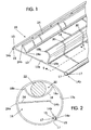
- a flashover protection cover 10 for covering an overhead power transmission line is illustrated in an uninstalled configuration ( Fig. 1 ) and in an installed configuration ( Fig. 2 ).
- the cover 10 includes a continuous, flexible panel 12 having an inner surface 12a and generally parallel opposite edge portions 14a and 14b.
- the opposite edge portions 14a, 14b are configured to be joined together to form a first longitudinally extending chamber 16 ( Fig. 2 ).
- edge portion 14b is configured to removably receive edge portion 14a therewithin.
- Edge portion 14a has an "arrowhead” configuration with shoulder portions 15 configured to be retained by elastic members 17 of edge portion 14b.
- the illustrated embodiment provides means for maintaining the panel edge portions 14a, 14b joined together under adverse conditions, while allowing the cover to be removed, if necessary, at a later time.
- the present invention is not limited to the illustrated embodiment.
- Alternative closure mechanisms having various shapes may be utilized, including, but not limited to, "L", “C” or “Z” shape closure devices.
- "hook and loop” fasteners such as Velcro ® brand fasteners (Velcro USA, Inc., Manchester, NH) may be utilized to hold the panel edge portions 14a, 14b together.
- an environmental sealant material is applied between the elastic members 17 of edge portion 14b.
- a preferred sealant material is a low modulus elastomer as described in copending, commonly assigned application of Chang, Serial Number 08/876,270, filed June 16, 1997 , the disclosure of which is incorporated herein by reference.
- a longitudinally extending first wall 18 is connected along a first edge portion 18a thereof to the panel inner surface 12a, as illustrated.
- the first wall 18 has a free edge portion 18b that is generally parallel with the first edge portion 18a.
- the first wall 18 has an arcuate shape.
- the first wall 18 is configured to form a second longitudinally extending chamber 20 within the first chamber 16.
- the second longitudinally extending chamber 20 is configured to enclose a power line 22 when the panel edge portions 14a, 14b are joined together.
- the first wall free edge portion 18b is spaced apart slightly from the panel inner surface 12a when the panel edge portions 14a, 14b are joined together.
- the first wall free edge portion 18b is spaced apart from the panel inner surface 12a by between about 1 and 2 millimeters (mm).
- the first wall may also be configured so that its free edge portion 18b abuts the panel inner surface 12a without any gap therebetween or with as minimal a gap as possible.
- the first wall 18 is not limited to the illustrated configuration.
- the first wall 18 may have a non-arcuate shape or may have an arcuate shape different from that illustrated, without departing from the spirit and intent of the present invention.
- a second wall 24 is connected along a first edge portion 24a thereof to the panel inner surface 12a , as illustrated.
- the second wall 24 is preferably configured to be longitudinally coextensive with the first chamber 16 when the panel edge portions 14a , 14b are joined together.
- the second wall 24 has a free edge portion 24b that is generally parallel with the first edge portion 24a .
- the second wall 24 and the first wall 18 are connected to the panel inner surface 12a in generally parallel, spaced apart relationship.
- the second wall 24 is preferably positioned adjacent the first wall free edge portion 18b when the panel edge portions 14a, 14b are joined together.
- This configuration inhibits electrical flashover or arcing from propagating from the power line 22 into the first chamber 16 between the first wall free edge portion 18b and the panel inner surface 12a. This may result if, for example, a grounded object comes into contact with the cover 10 near the edge portions 14a, 14b. A high stress may exist between the conductor and the grounded object which may result in flashover from the power line 22 to the grounded object between the first wall free edge portion 18b and the panel inner surface 12a.
- the present invention is not limited to the illustrated embodiment. Additional walls may be utilized to control potential arcing and flashover from a power line 22 enclosed within the second chamber 20.
- the cover 10 may have other non-circular cross-sectional configurations.
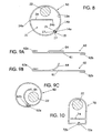
- an alternative embodiment of a flashover protection cover 50 is illustrated in Fig. 8 , wherein a single wall 24 is utilized. The wall 24 may extend substantially across the diameter of the cover 50.
- the embodiments illustrated in Figs. 2 , 8, 9C, and 10 may include an additional member overlying a gap between a wall free edge portion and the inside surface of the cover. For example, in Fig.
- an additional member may extend from the panel inner surface 12a and overlie the illustrated gap between the second wall free edge portion 24b and the panel inner surface 12a.
- the additional member provides protection against arcing through the gap.
- the additional member may have virtually any shape; however, a "U” or "V" shape may be preferred.
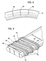
- a flashover protection cover may include a plurality of slots 30 formed in the first and second walls 18, 24. These slots 30 allow the flexible panel 10 with the first and second walls 18, 24 connected thereto to be coiled about a spool or other device. Without the slots 30, it may become difficult to coil any significant length of the panel around a spool without damage to the panel.
- slots in the first and second walls 18, 24 are formed therein in spaced apart sections, as illustrated in Fig. 4 . Because arcing may travel from a power line enclosed within the second chamber 20 through a slot 30, it is desirable to reduce the number of slots 30 required to effectively wind the clover 10 around a spool.
- slots 30 are formed in the first wall 18 of the cover 10 in repeating increments that facilitate the cover being wound around an elliptical-shaped spool. Slots formed in the first wall 18 may be offset from the slots in the second wall 24 to inhibit arcing into the first chamber 16.
- Various repeating patterns of slots may be utilized such that the cover 10 may be wound around various shapes and sizes of spools or other storage devices while reducing the number of slots 30, without departing from the spirit and intent of the present invention.
- the slots 30 are covered after the cover is unwound from a spool, either prior to or during installation around a power transmission line.
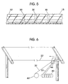
- a layer of insulating material 32 may be applied over the slots 30.
- the insulating material inhibits electrical arcing from passing through the slots 30.
- the slots 30 may have an adhesive or other insulating material smeared thereon.
- the flexible panel 12 and first and second walls 18, 24 are preferably formed from polymeric material of high dielectric strength including, but not limited to medium or high density polyethylene.
- the material out of which the flexible panel 12 and first and second walls 18, 24 are formed have good ultraviolet (UV) radiation protection, have good tracking, erosion, and abrasion resistance.
- UV ultraviolet
- tracking is a permanent damage to insulating material that leaves a carbonized conductive path that deteriorates the insulating properties of the material.
- the material out of which the flexible panel 12 and first and second walls 18, 24 are formed have a minimum life of 20 years within a 90°C environment.
- the flashover protection cover 10 is provided in a continuous length, preferably wound about a spool 40, or other means of delivery.
- Material 32 for covering portions of the cover having slots therein is preferably provided via a spool 42, or other means of delivery.
- a remotely-controlled installation tool 44 applies the insulating material 32 over the slots and encloses the cover 10 around the power line 22 as described above.
- the installation tool continuously moves along the span of the power line 22 performing the installation operations.
- the installation tool 44 may be stationary and the installed cover is advanced along the power line span.
- the installation tool serves as means for performing the functions of inserting a live electrical power line between the arcuate first wall and the panel inner surface.
- the installation tool also serves as means for performing the functions of securing the panel edge portions 14a, 14b together to enclose a live electrical power line within the longitudinally extending chamber 20, and for covering the plurality of slots 30 with electrically-insulative material 32 prior to securing the panel edge portions together.
- FIG. 7 A continuous length of flashover protection cover is provided to an installation tool (Block 100).
- a live power line 22 is inserted between the first wall 18 and the panel inner surface 12a (Block 110). Slots 30 within portions of the first and second walls are covered with insulating material 32 (Block 120).
- the panel edge portions 14a, 14b are secured together to enclose the live power line therewithin (Block 130).
- the installed cover may then be advanced along the power line span (Block 140).
- Installation operations are preferably performed via a remotely-controlled installation device which is either stationary or movable along a power line span.
- the installation tool will snap the panel edge portions 14a, 14b together and preferably move the cover down the power line span.
- the installation tool may be configured to "travel" the power line span as it secures a flashover protection cover thereto.
- flashover protection covers according to the present invention may be installed manually, as well.
- the present invention is advantageous because a flashover protection cover can be supplied in a continuous length to cover long spans of power transmission lines.
- flashover protection covers according to the present invention can be supplied in any length so as to cover entire conductor spans.
- the present invention may be utilized to cover power transmission lines up to and exceeding 25 millimeters in diameter and operating at up to and exceeding 25,000 volts, without limitation.
- FIG. 9A-9C a flashover protection cover 60 for an overhead power transmission line, according to another embodiment of the present invention is illustrated.
- Figs. 9A and 9B illustrate the flashover cover 60 in an uninstalled configuration.
- Fig. 9C is a cross-sectional view of the flashover protection cover 60 in an installed configuration.
- the cover 60 includes a panel 61 having opposite end portions 62a and 62b.
- a formable member 64 extends from the panel 61 between the end portions 62a, 62b as illustrated.
- the member 64 may be configured so as to obtain an arcuate shape when the end portions 62a and 62b are connected as illustrated in Fig. 9C .
- the member 64 may be thermoformable during installation.
- the illustrated end portions 62a and 62b have an arcuate shape and are configured to interlock as illustrated in Fig. 9C to secure the cover 60 around an electrical conductor 22.
- Fig. 10 is a cross-sectional view of a flashover protection cover 70, according to another embodiment of the present invention.
- the illustrated cover 70 has a "bell" shape and includes a wall 74 extending across the inside diameter of the cover. End portions 72a and 72b are configured to engage when the cover 70 is installed around an electrical conductor 22. Alternatively, the portion of the illustrated cover 70 including the wall 74 and end portions 72a and 72b may have a reduced diameter compared with the portion of the cover immediately surrounding the electrical conductor 22.
- an electrical power line span be covered with a single cover according to the present invention
- multiple covers may be utilized.
- a connector may be utilized to join multiple adjacent covers together along a span.
Abstract
Description
- The present invention relates generally to insulating covers and, more particularly, to insulating covers for overhead power transmission lines.
- Electrical power may be transmitted from a generation source to consumers via overhead conductors strung between towers or poles. Electrical power is typically transmitted in phases wherein multiple conductors are utilized. One or more of these conductors are "hot" conductors carrying a specified amount of alternating current electric power and one conductor serves as a ground. Flashover may result if contact is made between hot conductors or between hot conductors and other grounded objects. Non-grounded contact with a hot conductor, such as when a bird sits upon a hot conductor, typically does not result in flashover.
- Because uninsulated conductors are typically less expensive than insulated conductors, many electric power suppliers utilize uninsulated conductors for power transmission. With often hundreds of miles of transmission power lines, the use of uninsulated conductors can result in large cost savings to electric power suppliers. Uninsulated conductors are typically strung between towers or poles such that there is sufficient clearance between the conductors to avoid contact therebetween or with grounded objects.
- Although bare conductors may be less expensive to install than insulated conductors, potentially costly problems may arise as a result of their use. Adequate clearances between conductors and/or other grounded objects may not be sustainable during adverse weather conditions (i.e., storms and high winds). As a result, the potential for flashover caused by conductors contacting one another or another object may be increased. Another source of flashover may be caused by large birds and animals which have sufficient size to make contact with a hot conductor and a grounded object or other conductor. In addition, falling trees and tree branches may cause contact between hot conductors and ground, resulting in flashover.
- Flashover may result in a power outage which is undesirable to electric power suppliers and to consumers. For existing power transmission systems, electric power suppliers may find it desirable to replace bare conductors with insulated ones in order to eliminate the chance of flashover. Unfortunately, the cost of replacing bare conductors with insulated conductors may be expensive. Furthermore, an interruption in the delivery of power may be required to replace the conductors. This may be economically disadvantageous to an electric power supplier as well as being undesirable to electric power consumers.
- Insulating covers for temporary use in protecting workers from live power lines are available. Unfortunately, these insulating covers are typically designed for short term and/or local use. Furthermore, existing covers, such as Applicant's OLIC (Overhead Line Insulating Cover) product line, are typically available only in short lengths, typically ten feet (three meters) and less. Because of their shape and configuration, these temporary covers may be bulky and somewhat difficult to handle in longer lengths. A power line span between supporting towers or poles may exceed hundreds of meters. As a result, many of these temporary covers may be required to cover an entire span. Unfortunately, gaps between adjacent covers would be potential sources of flashover.
-
DE 28 12 524 A discloses a tube-like cover for the isolation of conductors, cables, conduits, or flexible tubes. It is an object of this document to provide a cover as an additional isolation for components as cited above. In order to solve this object, the cover forms, at each location over its circumference, two separated and independent isolating layers. A rim extends from the inner surface of the outer layer in a way that the rim abuts the inner surface of the outer layer. The cover can be used in demagnetisation coils for television devices for compensating any interfering fields. - It is, therefore, an object of the present invention to provide covers capable of protecting overhead power transmission lines from flashover caused by contact with a grounded object or another conductor..
- It is another object of the present invention to provide flashover protection covers that can be installed on existing power transmission lines without requiring a power outage during installation.
- It is yet another object of the present invention to supply flashover protection covers in a continuous configuration so as to cover an entire power transmission line span between supporting structures.
- The invention is directed to a flashover protection cover according to claim 1.
- These and other objects of the present invention are provided by flashover protection covers provided in continuous lengths that can enclose a live electrical power line within a chamber contained within another chamber. A flexible panel has an inner surface and generally parallel opposite edge portions configured to be joined together to form a first longitudinally extending chamber. A longitudinally extending first wall has an arcuate shape connected along an edge portion thereof to the inner surface of the panel. The first wall also has an opposite free edge portion. The first wall is configured to form a second longitudinally extending chamber within the first chamber. The second longitudinally extending chamber is configured to enclose a power line when the panel edge portions are joined together. The free edge portion of the first wall may abut, or be in close proximity to, the panel inner surface when the panel edge portions are joined together.
- A second wall is connected along an edge portion thereof to the inner surface of the panel and includes an opposite free edge portion. The second wall is configured to be longitudinally coextensive with the first chamber. The second wall edge portion is connected to the panel inner surface in generally parallel spaced apart relationship with the first wall edge portion such that the second wall is adjacent to the first wall free edge portion when the panel edge portions are joined together. The second wall inhibits electrical arcing from the power line into the first chamber between the first wall free edge portion and the panel inner surface. The second wall also increases the leakage length of the flashover protection cover.
- Flashover protection covers according to the present invention can be provided in continuous lengths sufficient to cover spans of power lines of any length. A plurality of slots are formed in the first and second walls of the cover to facilitate winding or coiling the uninstalled cover around a spool or similar device. A live electrical power line is positioned between the arcuate first wall and the panel inner surface. The panel edge portions are then secured together to enclose the power line within the longitudinally extending chamber defined thereby. The plurality of slots that facilitate providing the cover in a generally flat uninstalled configuration are covered during installation with electrically-insulating material prior to securing the panel edge portions together. As the panel edge portions are secured together, the cover may be advanced along the power line span. Alternatively, a flashover protection cover, according to the present invention, may be applied to a live power line continuously. Installation operations are preferably performed via a remotely-controlled device which is either stationary or movable along a power line span.
- Flashover protection covers according to the present invention are advantageous because they can be installed on existing power transmission lines without requiring the power lines to be removed from service. Covers according to the present invention provide electrical insulation sufficient to prevent power line flashover if adjacent power lines touch, such as during high winds, or if a grounded object, such as a tree or animal, makes contact with a power line. By reducing the potential for flashover, the possibility of power outages is diminished. Furthermore, hazards associated with flashover, such as fire, are also diminished.
-
-
Fig. 1 illustrates an uninstalled flashover protection cover for an overhead power transmission line, according to aspects of the present invention. -
Fig. 2 is a cross-sectional view of the flashover protection cover ofFig. 1 in an installed configuration enclosing a power transmission line. -
Fig. 3 illustrates slots formed in the wall portions of the flashover protection cover ofFig. 1 which allow the cover in its uninstalled configuration to be wound around a spool. -
Fig. 4 illustrates the flashover protection cover ofFig. 1 wound around a spool. -
Fig. 5 illustrates insulating material covering the slots in the wall portions of a flashover protection cover. -
Fig. 6 illustrates enclosing an entire power transmission line span with a flashover protection cover according to the present invention. -
Fig. 7 is a flowchart schematically illustrating operations for enclosing a power transmission line with a flashover protection cover according to the present invention. -
Fig. 8 is a cross-sectional view of the flashover protection cover according to another embodiment in an installed configuration enclosing a power transmission line. -
Figs. 9A-9B illustrate an uninstalled flashover protection cover for an overhead power transmission line, according to another embodiment of the present invention. -
Fig. 9C is a cross-sectional view of the flashover protection cover ofFigs. 9A-9B in an installed configuration. -
Fig. 10 is a cross-sectional view of the flashover protection cover according to another embodiment. - The present invention now will be described more fully hereinafter with reference to the accompanying drawings, in which preferred embodiments of the invention are shown. This invention may, however, be embodied in many different forms and should not be construed as limited to the embodiments set forth herein; rather, these embodiments are provided so that this disclosure will be thorough and complete, and will fully convey the scope of the invention to those skilled in the art. Like numbers refer to like elements throughout.
- Referring now to
Figs. 1-2 , aflashover protection cover 10 for covering an overhead power transmission line, according to aspects of the present invention, is illustrated in an uninstalled configuration (Fig. 1 ) and in an installed configuration (Fig. 2 ). Thecover 10 includes a continuous,flexible panel 12 having aninner surface 12a and generally parallelopposite edge portions opposite edge portions Fig. 2 ). - In the illustrated embodiment,
edge portion 14b is configured to removably receiveedge portion 14a therewithin.Edge portion 14a has an "arrowhead" configuration withshoulder portions 15 configured to be retained byelastic members 17 ofedge portion 14b. The illustrated embodiment provides means for maintaining thepanel edge portions panel edge portions elastic members 17 ofedge portion 14b. A preferred sealant material is a low modulus elastomer as described in copending, commonly assigned application of Chang, Serial Number08/876,270, filed June 16, 1997 , the disclosure of which is incorporated herein by reference. - A longitudinally extending
first wall 18 is connected along afirst edge portion 18a thereof to the panelinner surface 12a, as illustrated. Thefirst wall 18 has afree edge portion 18b that is generally parallel with thefirst edge portion 18a. Preferably, thefirst wall 18 has an arcuate shape. As illustrated inFig. 2 , thefirst wall 18 is configured to form a secondlongitudinally extending chamber 20 within thefirst chamber 16. The second longitudinally extendingchamber 20 is configured to enclose apower line 22 when thepanel edge portions - As illustrated in
Fig. 2 , the first wallfree edge portion 18b is spaced apart slightly from the panelinner surface 12a when thepanel edge portions free edge portion 18b is spaced apart from the panelinner surface 12a by between about 1 and 2 millimeters (mm). The first wall may also be configured so that itsfree edge portion 18b abuts the panelinner surface 12a without any gap therebetween or with as minimal a gap as possible. Thefirst wall 18 is not limited to the illustrated configuration. Thefirst wall 18 may have a non-arcuate shape or may have an arcuate shape different from that illustrated, without departing from the spirit and intent of the present invention. - Still referring to
Figs. 1-2 , asecond wall 24 is connected along afirst edge portion 24a thereof to the panelinner surface 12a, as illustrated. Thesecond wall 24 is preferably configured to be longitudinally coextensive with thefirst chamber 16 when thepanel edge portions second wall 24 has afree edge portion 24b that is generally parallel with thefirst edge portion 24a. Thesecond wall 24 and thefirst wall 18 are connected to the panelinner surface 12a in generally parallel, spaced apart relationship. Thesecond wall 24 is preferably positioned adjacent the first wallfree edge portion 18b when thepanel edge portions power line 22 into thefirst chamber 16 between the first wallfree edge portion 18b and the panelinner surface 12a. This may result if, for example, a grounded object comes into contact with thecover 10 near theedge portions power line 22 to the grounded object between the first wallfree edge portion 18b and the panelinner surface 12a. - The present invention is not limited to the illustrated embodiment. Additional walls may be utilized to control potential arcing and flashover from a
power line 22 enclosed within thesecond chamber 20. Furthermore, thecover 10 may have other non-circular cross-sectional configurations. For example, an alternative embodiment of aflashover protection cover 50 is illustrated inFig. 8 , wherein asingle wall 24 is utilized. Thewall 24 may extend substantially across the diameter of thecover 50. Additionally, the embodiments illustrated inFigs. 2 ,8, 9C, and 10 may include an additional member overlying a gap between a wall free edge portion and the inside surface of the cover. For example, inFig. 2 , an additional member, not shown, may extend from the panelinner surface 12a and overlie the illustrated gap between the second wallfree edge portion 24b and the panelinner surface 12a. The additional member provides protection against arcing through the gap. The additional member may have virtually any shape; however, a "U" or "V" shape may be preferred. - Referring now to
Figs. 3-4 , a flashover protection cover, according to the present invention, may include a plurality ofslots 30 formed in the first andsecond walls slots 30 allow theflexible panel 10 with the first andsecond walls slots 30, it may become difficult to coil any significant length of the panel around a spool without damage to the panel. - Preferably, slots in the first and
second walls Fig. 4 . Because arcing may travel from a power line enclosed within thesecond chamber 20 through aslot 30, it is desirable to reduce the number ofslots 30 required to effectively wind theclover 10 around a spool. In the illustrated embodiment ofFig. 4 ,slots 30 are formed in thefirst wall 18 of thecover 10 in repeating increments that facilitate the cover being wound around an elliptical-shaped spool. Slots formed in thefirst wall 18 may be offset from the slots in thesecond wall 24 to inhibit arcing into thefirst chamber 16. Various repeating patterns of slots may be utilized such that thecover 10 may be wound around various shapes and sizes of spools or other storage devices while reducing the number ofslots 30, without departing from the spirit and intent of the present invention. - Preferably, the
slots 30 are covered after the cover is unwound from a spool, either prior to or during installation around a power transmission line. As illustrated inFig. 5 , a layer of insulatingmaterial 32 may be applied over theslots 30. The insulating material inhibits electrical arcing from passing through theslots 30. In addition, theslots 30 may have an adhesive or other insulating material smeared thereon. - The
flexible panel 12 and first andsecond walls flexible panel 12 and first andsecond walls flexible panel 12 and first andsecond walls - Referring now to
Figs. 6-7 , operations for applying a flashover protection cover, according to the present invention, to a power transmission line are illustrated. Theflashover protection cover 10 is provided in a continuous length, preferably wound about aspool 40, or other means of delivery.Material 32 for covering portions of the cover having slots therein is preferably provided via aspool 42, or other means of delivery. A remotely-controlledinstallation tool 44 applies the insulatingmaterial 32 over the slots and encloses thecover 10 around thepower line 22 as described above. The installation tool continuously moves along the span of thepower line 22 performing the installation operations. Alternatively, theinstallation tool 44 may be stationary and the installed cover is advanced along the power line span. - The installation tool serves as means for performing the functions of inserting a live electrical power line between the arcuate first wall and the panel inner surface. The installation tool also serves as means for performing the functions of securing the
panel edge portions longitudinally extending chamber 20, and for covering the plurality ofslots 30 with electrically-insulative material 32 prior to securing the panel edge portions together. - The above-described operations for installing a flashover protection cover on a live power line are schematically illustrated in
Fig. 7 . A continuous length of flashover protection cover is provided to an installation tool (Block 100). Alive power line 22 is inserted between thefirst wall 18 and the panelinner surface 12a (Block 110).Slots 30 within portions of the first and second walls are covered with insulating material 32 (Block 120). Thepanel edge portions - Installation operations are preferably performed via a remotely-controlled installation device which is either stationary or movable along a power line span. As the flashover protection cover is paid off a spool and onto a conductor, the installation tool will snap the
panel edge portions - The present invention is advantageous because a flashover protection cover can be supplied in a continuous length to cover long spans of power transmission lines. Preferably, flashover protection covers according to the present invention can be supplied in any length so as to cover entire conductor spans. The present invention may be utilized to cover power transmission lines up to and exceeding 25 millimeters in diameter and operating at up to and exceeding 25,000 volts, without limitation.
- Referring now to
Figs. 9A-9C ,aflashover protection cover 60 for an overhead power transmission line, according to another embodiment of the present invention is illustrated.Figs. 9A and9B illustrate theflashover cover 60 in an uninstalled configuration.Fig. 9C is a cross-sectional view of theflashover protection cover 60 in an installed configuration. Thecover 60 includes apanel 61 havingopposite end portions formable member 64 extends from thepanel 61 between theend portions member 64 may be configured so as to obtain an arcuate shape when theend portions Fig. 9C . Alternatively, themember 64 may be thermoformable during installation. Theillustrated end portions Fig. 9C to secure thecover 60 around anelectrical conductor 22. -
Fig. 10 is a cross-sectional view of aflashover protection cover 70, according to another embodiment of the present invention. The illustratedcover 70 has a "bell" shape and includes awall 74 extending across the inside diameter of the cover.End portions cover 70 is installed around anelectrical conductor 22. Alternatively, the portion of the illustratedcover 70 including thewall 74 andend portions electrical conductor 22. - Although it is preferable that an electrical power line span be covered with a single cover according to the present invention, multiple covers may be utilized. A connector may be utilized to join multiple adjacent covers together along a span.
- The foregoing is illustrative of the present invention and is not to be construed as limiting thereof. Although a few exemplary embodiments of this invention have been described, those skilled in the art will readily appreciate that many modifications are possible in the exemplary embodiments without materially departing from the scope of the invention as defined in the claims.
Claims (11)
- A flashover protection cover (10, 50, 60, 70) for an electrical power line (22), comprising:a flexible panel (12) having an inner surface (12a) and generally parallel opposite edge portions (14a, 14b), said edge portions being configured to be joined together to form a first longitudinally extending chamber (16); anda longitudinally extending first wall (18) connected along an edge portion (18a) of said first wall to said inner surface (12a) and having an opposite free edge portion (18b), wherein said first wall is longitudinally coextensive with said first longitudinally extending chamber (16), said first wall (18) configured to form a second longitudinally extending chamber (20) within said first chamber (16) when said panel edge portions are joined together, wherein said second longitudinally extending chamber (20) is configured to enclose an electrical power line (22), and wherein said second longitudinally extending chamber (20) is longitudinally coextensive with said first longitudinally extending chamber (16), and further comprising means (24) for inhibiting electrical arcing from said power line (22) into said first chamber (16) between the free edge portion (18b) of said first wall and the panel inner surface (12a).
- A flashover protection cover according to Claim 1 wherein the means (24) for inhibiting electrical arcing comprises a second wall (24) connected along an edge portion (24a) of said second wall to said inner surface (12a) and having an opposite free edge portion (24b), wherein said second wall (24) is longitudinally coextensive with said first longitudinally extending chamber (16).
- A flashover protection cover according to Claim 2 wherein said second wall edge portion (24a) is connected to said panel inner surface (12a) in generally parallel spaced apart relationship with said first wall edge portion (18a) such that said second wall (24) is adjacent said first wall free edge portion (18b) when said panel edge portions (14a, 14b) are joined together to thereby inhibit electrical arcing from said power line (22) into said first chamber (16) between said first wall free edge portion (18b) and said panel inner surface (12a).
- A flashover protection cover according to Claim 1 wherein said first wall (18) has an arcuate shape.
- A flashover protection cover according to Claim 1 wherein said free edge portion (18b) of said first wall abuts said panel inner surface (12a) when said panel edge portions (14a, 14b) are joined together.
- A flashover protection cover according to Claim 2 further comprising a plurality of slots (30) formed in said first and second walls (18, 24) to facilitate winding said cover in an uninstalled configuration around a spool.
- A flashover protection cover according to Claim 6 further comprising a layer of insulating material (32) overlying said slots.
- A flashover protection cover according to Claim 2 wherein said panel (12) and said first and second walls (18, 24) are formed from polymeric material of high dielectric strength.
- A flashover protection cover according to Claim 2 wherein said free edge portion (18b) of said first wall abuts said panel inner surface (12a) when said panel edge portions (14a, 14b) are joined together.
- A flashover protection cover according to Claim 2 wherein said panel (12) and said first and second walls (18, 24) are formed from polymeric material of high dielectric strength.
- A flashover protection cover according to one of claims 1-10 further comprising means (30) for enabling said cover to be wound in an uninstalled configuration around a spool.
Applications Claiming Priority (3)
| Application Number | Priority Date | Filing Date | Title |
|---|---|---|---|
| US988000 | 1997-12-10 | ||
| US08/988,000 US6020560A (en) | 1997-12-10 | 1997-12-10 | Flashover protection cover for electrical power lines |
| PCT/US1998/025886 WO1999030399A1 (en) | 1997-12-10 | 1998-12-08 | Flashover protection cover for electrical power lines |
Publications (2)
| Publication Number | Publication Date |
|---|---|
| EP1038345A1 EP1038345A1 (en) | 2000-09-27 |
| EP1038345B1 true EP1038345B1 (en) | 2010-05-19 |
Family
ID=25533766
Family Applications (1)
| Application Number | Title | Priority Date | Filing Date |
|---|---|---|---|
| EP98964705A Expired - Lifetime EP1038345B1 (en) | 1997-12-10 | 1998-12-08 | Flashover protection cover for electrical power lines |
Country Status (16)
| Country | Link |
|---|---|
| US (2) | US6020560A (en) |
| EP (1) | EP1038345B1 (en) |
| JP (1) | JP4823416B2 (en) |
| KR (1) | KR100596951B1 (en) |
| CN (1) | CN1175538C (en) |
| AT (1) | ATE468644T1 (en) |
| AU (1) | AU754842B2 (en) |
| BR (1) | BR9812781B1 (en) |
| CA (1) | CA2309429C (en) |
| DE (1) | DE69841675D1 (en) |
| ES (1) | ES2348497T3 (en) |
| IL (2) | IL135975A (en) |
| MX (1) | MXPA00004537A (en) |
| NZ (1) | NZ504297A (en) |
| PT (1) | PT1038345E (en) |
| WO (1) | WO1999030399A1 (en) |
Families Citing this family (23)
| Publication number | Priority date | Publication date | Assignee | Title |
|---|---|---|---|---|
| US6094792C1 (en) * | 1998-12-15 | 2002-05-21 | Raychem Corp | Apparatus for installing flashover protection covers on energized electrical power lines |
| US6219907B1 (en) | 1999-10-12 | 2001-04-24 | Tyco Electronics Corporation | Hand-held apparatus for installing flashover protection covers on energized electrical conductors and equipment |
| US6812400B1 (en) * | 2000-01-25 | 2004-11-02 | Michael Lynch | Bird guard |
| IES20010787A2 (en) * | 2001-08-30 | 2003-03-19 | Paul Hallinan | Cabling apparatus |
| AU2002360434A1 (en) * | 2001-11-28 | 2003-06-10 | Douglas J. Wulff | Power transmission shield |
| ITTO20030876A1 (en) * | 2003-11-05 | 2005-05-06 | Tubiflex Spa | DUCT FOR OBTAINING SLEEVES FOR THE CONDUCTED HOUSING OF CONDITIONING SYSTEMS. |
| DE102005017472B3 (en) * | 2005-04-12 | 2006-09-07 | Cellpack Gmbh | Two or multipart insulation system for a medium voltage cable fitting with self holding cable connection has snap coupling facing surfaces and inner and outer electrically conductive layers on insulation |
| US7456363B2 (en) * | 2005-11-29 | 2008-11-25 | Hastings Fiber Glass Products, Inc. | Electric wire protective tube and insulating coupler |
| KR100974093B1 (en) | 2009-10-30 | 2010-08-04 | 한국전력공사 | Insulation cover of electric wire |
| US8895859B2 (en) * | 2011-06-17 | 2014-11-25 | Verizon Patent And Licensing Inc. | Temporary cable cover |
| CN102592758A (en) * | 2012-03-12 | 2012-07-18 | 李彦朋 | Insulating sheath for overhead line |
| US8859898B2 (en) | 2012-09-20 | 2014-10-14 | Tyco Electronics Corporation | Power transmission line covers and methods and assemblies using same |
| WO2021183576A1 (en) * | 2020-03-13 | 2021-09-16 | Getman Anya L | Methods and devices for electrically insulating a power line |
| US11948703B2 (en) * | 2019-04-01 | 2024-04-02 | Anya L. Getman | Methods and devices for electrically insulating a power line |
| US9702485B2 (en) | 2014-12-10 | 2017-07-11 | Te Connectivity Corporation | Covers for electrical distribution lines and insulators and methods and systems including same |
| US20160260660A1 (en) * | 2015-03-04 | 2016-09-08 | Delta Electronics, Inc. | Electronic device and electronic package thereof |
| US10481360B2 (en) | 2016-11-16 | 2019-11-19 | Commscope Technologies Llc | Telecommunications cabling system |
| JP6157710B1 (en) * | 2016-12-01 | 2017-07-05 | 日本ジッパーチュービング株式会社 | Bundling protection member |
| BE1024410B9 (en) * | 2017-06-21 | 2018-03-07 | Asg Technics Bvba | Safety screen against arcs and / or flame spread |
| CN108598840A (en) * | 2018-03-24 | 2018-09-28 | 浙江海宁普赛自动化科技有限公司 | The method of sheath is covered in a kind of assembling of reference power supply line |
| US11708846B2 (en) * | 2018-10-30 | 2023-07-25 | Trang Tran | Connection device |
| CN109356393B (en) * | 2018-10-30 | 2021-05-18 | 绍兴嘉越纺织机械有限公司 | Building site atress adds protects wire device that recycles |
| ES2804086A1 (en) * | 2019-07-22 | 2021-02-03 | Corporative Int R&H Europe S L | Electrical protection device. (Machine-translation by Google Translate, not legally binding) |
Family Cites Families (46)
| Publication number | Priority date | Publication date | Assignee | Title |
|---|---|---|---|---|
| USRE24613E (en) | 1959-03-03 | hageltorn | ||
| US24613A (en) * | 1859-07-05 | Improvement in harvesting-machines | ||
| US1224970A (en) * | 1916-11-03 | 1917-05-08 | American Telephone & Telegraph | Lineman's shield. |
| US1435311A (en) * | 1921-01-10 | 1922-11-14 | Grace P Knight | Flexible tubular clamping jacket |
| US1485994A (en) * | 1922-12-21 | 1924-03-04 | Moses B Salisbury | Protective insulating sleeve |
| US1988604A (en) * | 1931-05-13 | 1935-01-22 | Goodrich Co B F | Lineman's protective sleeve and method of making the same |
| US1988435A (en) * | 1931-10-01 | 1935-01-22 | Goodrich Co B F | Lineman's protective device |
| US2408253A (en) * | 1943-08-27 | 1946-09-24 | Barney A Diebold | Guard or protector for electric cables |
| US2770667A (en) * | 1950-11-13 | 1956-11-13 | Kearney James R Corp | Electrical protective devices |
| US2927146A (en) * | 1955-06-06 | 1960-03-01 | W H Salisbury & Company | Protective device |
| US3089915A (en) * | 1960-06-27 | 1963-05-14 | Walter A Plummer | Electrically shielded tubular jacket |
| JPS4216925Y1 (en) * | 1965-07-28 | 1967-09-29 | ||
| US3262083A (en) * | 1965-10-08 | 1966-07-19 | Johnson Plastic Corp | Apparatus for electrical raceway and decorative moulding |
| US3517702A (en) * | 1966-07-08 | 1970-06-30 | Amp Inc | Flexible material to form a tubular member |
| US3459870A (en) * | 1967-04-10 | 1969-08-05 | Walter A Plummer | High dielectric protective jacket for temporary assembly about high tension conductors |
| US3428742A (en) * | 1967-09-11 | 1969-02-18 | Essex Wire Corp | Guy guard and clip |
| US3587657A (en) * | 1968-06-19 | 1971-06-28 | Flexigrip Inc | Zipper tubing |
| FR1585394A (en) * | 1968-11-18 | 1970-01-16 | ||
| JPS4944238Y1 (en) * | 1970-04-13 | 1974-12-04 | ||
| JPS503198Y1 (en) * | 1970-08-20 | 1975-01-28 | ||
| JPS5041520Y2 (en) * | 1971-10-02 | 1975-11-26 | ||
| US3721762A (en) * | 1971-12-08 | 1973-03-20 | Plastic J Corp | Electrical raceway and decorative molding |
| US3819139A (en) * | 1972-05-17 | 1974-06-25 | Heyman Mfg Co | Cable hanger |
| US3786171A (en) * | 1973-01-22 | 1974-01-15 | Kvoda Plastics Ltd | Integral hinged wiring raceway |
| US3846575A (en) * | 1973-07-16 | 1974-11-05 | Reliable Electric Co | Cable sheath and ready access closure including a cable sheath |
| US3900697A (en) * | 1974-05-02 | 1975-08-19 | Masamitsu Yotsugi | Electric wire insulating cover |
| JPS5735847Y2 (en) * | 1977-06-30 | 1982-08-09 | ||
| DE2812524A1 (en) * | 1978-03-22 | 1979-09-27 | Lackdraht Union Gmbh | Cable and tube hose-shaped wrap-round insulation - has fin formed on sleeve along entire length of insulation to completely line inner seam or sleeve |
| SE420552B (en) * | 1979-05-03 | 1981-10-12 | Ericsson Telefon Ab L M | Ribbon-shaped device for forming a rudder-shaped sign and protective sheath |
| JPS5852973Y2 (en) * | 1979-08-20 | 1983-12-02 | 東京電力株式会社 | Insulation protection cover |
| US4422478A (en) * | 1980-02-23 | 1983-12-27 | Raychem Limited | Closure device |
| JPS6110427Y2 (en) * | 1980-04-24 | 1986-04-03 | ||
| US4453353A (en) * | 1981-09-14 | 1984-06-12 | Robin Products Company | Guy wire protector |
| US4399840A (en) * | 1982-04-26 | 1983-08-23 | Morris M. Lee | Closure member |
| DE3317445A1 (en) * | 1983-05-13 | 1984-11-15 | Fa. A. Raymond, 7850 Lörrach | PROTECTIVE RING FOR OVERLAND CABLES |
| US4628145A (en) * | 1985-11-22 | 1986-12-09 | Nestor Kolcio | Protective cover for electrical conductors |
| US4944976A (en) * | 1989-02-17 | 1990-07-31 | The Zippertubing Co. | Semi-rigid plastic jacket with interlocking longitudinal seam |
| DE4019130C2 (en) * | 1990-06-13 | 2000-03-23 | Wago Verwaltungs Gmbh | Floor clamp for electrical conductors |
| FR2687256B1 (en) * | 1992-02-12 | 1994-04-08 | Sofanou | TUBULAR SOUND INSULATION TUBING FOR ELECTRICAL CABLES AND MANUFACTURING METHOD. |
| US5505230A (en) * | 1992-03-19 | 1996-04-09 | Proprietary Technology, Inc. | Means for protecting conducting equipment |
| US5377940A (en) * | 1993-03-19 | 1995-01-03 | Bell Helicopter Textron Inc. | Self-restraining loop clamp |
| JPH0749695Y2 (en) * | 1993-11-05 | 1995-11-13 | 中部電力株式会社 | Insulation cover |
| US5566622A (en) * | 1995-06-02 | 1996-10-22 | Ziaylek, Jr.; Theodore | Collapsible hose bridging apparatus |
| DE19541137A1 (en) * | 1995-10-30 | 1997-05-07 | Wago Verwaltungs Gmbh | Terminal with cut-and-grip contacts for front of insulating housing |
| US5796032A (en) * | 1997-05-19 | 1998-08-18 | Hadley; William A. | Electric wire insulating cover inspection device |
| US6094792C1 (en) * | 1998-12-15 | 2002-05-21 | Raychem Corp | Apparatus for installing flashover protection covers on energized electrical power lines |
-
1997
- 1997-12-10 US US08/988,000 patent/US6020560A/en not_active Expired - Lifetime
-
1998
- 1998-12-08 CN CNB988120038A patent/CN1175538C/en not_active Expired - Lifetime
- 1998-12-08 IL IL13597598A patent/IL135975A/en not_active IP Right Cessation
- 1998-12-08 JP JP2000524848A patent/JP4823416B2/en not_active Expired - Lifetime
- 1998-12-08 NZ NZ504297A patent/NZ504297A/en not_active IP Right Cessation
- 1998-12-08 BR BRPI9812781-0A patent/BR9812781B1/en not_active IP Right Cessation
- 1998-12-08 AU AU19968/99A patent/AU754842B2/en not_active Ceased
- 1998-12-08 CA CA002309429A patent/CA2309429C/en not_active Expired - Fee Related
- 1998-12-08 PT PT98964705T patent/PT1038345E/en unknown
- 1998-12-08 WO PCT/US1998/025886 patent/WO1999030399A1/en active IP Right Grant
- 1998-12-08 DE DE69841675T patent/DE69841675D1/en not_active Expired - Lifetime
- 1998-12-08 ES ES98964705T patent/ES2348497T3/en not_active Expired - Lifetime
- 1998-12-08 AT AT98964705T patent/ATE468644T1/en not_active IP Right Cessation
- 1998-12-08 KR KR1020007005079A patent/KR100596951B1/en not_active IP Right Cessation
- 1998-12-08 MX MXPA00004537A patent/MXPA00004537A/en unknown
- 1998-12-08 EP EP98964705A patent/EP1038345B1/en not_active Expired - Lifetime
-
1999
- 1999-02-11 US US09/249,234 patent/US6239357B1/en not_active Expired - Lifetime
-
2005
- 2005-04-11 IL IL167964A patent/IL167964A/en not_active IP Right Cessation
Also Published As
| Publication number | Publication date |
|---|---|
| CN1175538C (en) | 2004-11-10 |
| US6239357B1 (en) | 2001-05-29 |
| AU1996899A (en) | 1999-06-28 |
| JP4823416B2 (en) | 2011-11-24 |
| NZ504297A (en) | 2002-03-01 |
| CA2309429C (en) | 2007-06-26 |
| US6020560A (en) | 2000-02-01 |
| BR9812781A (en) | 2000-10-03 |
| MXPA00004537A (en) | 2002-04-24 |
| ES2348497T3 (en) | 2010-12-07 |
| DE69841675D1 (en) | 2010-07-01 |
| IL167964A (en) | 2010-11-30 |
| KR100596951B1 (en) | 2006-09-11 |
| IL135975A (en) | 2005-08-31 |
| CN1281593A (en) | 2001-01-24 |
| CA2309429A1 (en) | 1999-06-17 |
| PT1038345E (en) | 2010-07-19 |
| KR20010052098A (en) | 2001-06-25 |
| IL135975A0 (en) | 2001-05-20 |
| JP2001526453A (en) | 2001-12-18 |
| AU754842B2 (en) | 2002-11-28 |
| EP1038345A1 (en) | 2000-09-27 |
| WO1999030399A1 (en) | 1999-06-17 |
| BR9812781B1 (en) | 2011-08-23 |
| ATE468644T1 (en) | 2010-06-15 |
Similar Documents
| Publication | Publication Date | Title |
|---|---|---|
| EP1038345B1 (en) | Flashover protection cover for electrical power lines | |
| US8859898B2 (en) | Power transmission line covers and methods and assemblies using same | |
| CA2400618C (en) | Wildlife guard for electrical insulator bushings | |
| US7068893B2 (en) | Optical fiber composite electrical power cable | |
| EP1652280B1 (en) | Method for shielding the magnetic field generated by an electrical power transmission line and electrical power transmission line so shielded | |
| EP0924831B1 (en) | Flexible power and signal distribution system | |
| US20220413241A1 (en) | A system for guiding a dielectric cable from phase-to-ground potential | |
| GB2267182B (en) | Overhead optical transmission system | |
| EP1221188B1 (en) | Hand-held apparatus for installing flashover protection covers on energized electrical conductors and equipment | |
| JP3603162B2 (en) | Bare wire insulation cover and insulation structure | |
| RU2383075C1 (en) | Optic communication cable | |
| RU2334292C1 (en) | Optical communication cable | |
| KR100925040B1 (en) | Insulation cover for protecting a conductor line | |
| US4002920A (en) | Underground electrical reticulation systems and transformers therefor | |
| KR20060028566A (en) | A power cable structure for easy fault location | |
| JPS612205A (en) | Electric conductor assembly | |
| JP2000133054A5 (en) | ||
| SE437740B (en) | Cable for power supply of electric apparatuses in an installation |
Legal Events
| Date | Code | Title | Description |
|---|---|---|---|
| PUAI | Public reference made under article 153(3) epc to a published international application that has entered the european phase |
Free format text: ORIGINAL CODE: 0009012 |
|
| 17P | Request for examination filed |
Effective date: 20000509 |
|
| AK | Designated contracting states |
Kind code of ref document: A1 Designated state(s): AT BE CH DE DK ES FI FR GB IE IT LI NL PT SE |
|
| 17Q | First examination report despatched |
Effective date: 20080411 |
|
| GRAP | Despatch of communication of intention to grant a patent |
Free format text: ORIGINAL CODE: EPIDOSNIGR1 |
|
| GRAS | Grant fee paid |
Free format text: ORIGINAL CODE: EPIDOSNIGR3 |
|
| GRAA | (expected) grant |
Free format text: ORIGINAL CODE: 0009210 |
|
| AK | Designated contracting states |
Kind code of ref document: B1 Designated state(s): AT BE CH DE DK ES FI FR GB IE IT LI NL PT SE |
|
| REG | Reference to a national code |
Ref country code: GB Ref legal event code: FG4D |
|
| REG | Reference to a national code |
Ref country code: CH Ref legal event code: EP |
|
| REG | Reference to a national code |
Ref country code: IE Ref legal event code: FG4D |
|
| REF | Corresponds to: |
Ref document number: 69841675 Country of ref document: DE Date of ref document: 20100701 Kind code of ref document: P |
|
| REG | Reference to a national code |
Ref country code: PT Ref legal event code: SC4A Free format text: AVAILABILITY OF NATIONAL TRANSLATION Effective date: 20100712 |
|
| REG | Reference to a national code |
Ref country code: SE Ref legal event code: TRGR |
|
| REG | Reference to a national code |
Ref country code: NL Ref legal event code: VDEP Effective date: 20100519 |
|
| REG | Reference to a national code |
Ref country code: ES Ref legal event code: FG2A Effective date: 20101124 |
|
| PG25 | Lapsed in a contracting state [announced via postgrant information from national office to epo] |
Ref country code: FI Free format text: LAPSE BECAUSE OF FAILURE TO SUBMIT A TRANSLATION OF THE DESCRIPTION OR TO PAY THE FEE WITHIN THE PRESCRIBED TIME-LIMIT Effective date: 20100519 Ref country code: AT Free format text: LAPSE BECAUSE OF FAILURE TO SUBMIT A TRANSLATION OF THE DESCRIPTION OR TO PAY THE FEE WITHIN THE PRESCRIBED TIME-LIMIT Effective date: 20100519 |
|
| PG25 | Lapsed in a contracting state [announced via postgrant information from national office to epo] |
Ref country code: NL Free format text: LAPSE BECAUSE OF FAILURE TO SUBMIT A TRANSLATION OF THE DESCRIPTION OR TO PAY THE FEE WITHIN THE PRESCRIBED TIME-LIMIT Effective date: 20100519 Ref country code: DK Free format text: LAPSE BECAUSE OF FAILURE TO SUBMIT A TRANSLATION OF THE DESCRIPTION OR TO PAY THE FEE WITHIN THE PRESCRIBED TIME-LIMIT Effective date: 20100519 |
|
| PG25 | Lapsed in a contracting state [announced via postgrant information from national office to epo] |
Ref country code: BE Free format text: LAPSE BECAUSE OF FAILURE TO SUBMIT A TRANSLATION OF THE DESCRIPTION OR TO PAY THE FEE WITHIN THE PRESCRIBED TIME-LIMIT Effective date: 20100519 |
|
| PLBE | No opposition filed within time limit |
Free format text: ORIGINAL CODE: 0009261 |
|
| STAA | Information on the status of an ep patent application or granted ep patent |
Free format text: STATUS: NO OPPOSITION FILED WITHIN TIME LIMIT |
|
| 26N | No opposition filed |
Effective date: 20110222 |
|
| REG | Reference to a national code |
Ref country code: DE Ref legal event code: R097 Ref document number: 69841675 Country of ref document: DE Effective date: 20110221 |
|
| REG | Reference to a national code |
Ref country code: CH Ref legal event code: PL |
|
| PG25 | Lapsed in a contracting state [announced via postgrant information from national office to epo] |
Ref country code: CH Free format text: LAPSE BECAUSE OF NON-PAYMENT OF DUE FEES Effective date: 20101231 Ref country code: IE Free format text: LAPSE BECAUSE OF NON-PAYMENT OF DUE FEES Effective date: 20101208 Ref country code: LI Free format text: LAPSE BECAUSE OF NON-PAYMENT OF DUE FEES Effective date: 20101231 |
|
| REG | Reference to a national code |
Ref country code: FR Ref legal event code: PLFP Year of fee payment: 18 |
|
| PGFP | Annual fee paid to national office [announced via postgrant information from national office to epo] |
Ref country code: SE Payment date: 20151230 Year of fee payment: 18 |
|
| REG | Reference to a national code |
Ref country code: FR Ref legal event code: PLFP Year of fee payment: 19 |
|
| PG25 | Lapsed in a contracting state [announced via postgrant information from national office to epo] |
Ref country code: IT Free format text: LAPSE BECAUSE OF NON-PAYMENT OF DUE FEES Effective date: 20151208 |
|
| REG | Reference to a national code |
Ref country code: DE Ref legal event code: R082 Ref document number: 69841675 Country of ref document: DE Representative=s name: SCHMITT-NILSON SCHRAUD WAIBEL WOHLFROM PATENTA, DE |
|
| REG | Reference to a national code |
Ref country code: SE Ref legal event code: EUG |
|
| PG25 | Lapsed in a contracting state [announced via postgrant information from national office to epo] |
Ref country code: IT Free format text: LAPSE BECAUSE OF NON-PAYMENT OF DUE FEES Effective date: 20151208 Ref country code: SE Free format text: LAPSE BECAUSE OF NON-PAYMENT OF DUE FEES Effective date: 20161209 |
|
| PGFP | Annual fee paid to national office [announced via postgrant information from national office to epo] |
Ref country code: IT Payment date: 20151222 Year of fee payment: 18 |
|
| PGRI | Patent reinstated in contracting state [announced from national office to epo] |
Ref country code: IT Effective date: 20170710 |
|
| PG25 | Lapsed in a contracting state [announced via postgrant information from national office to epo] |
Ref country code: IT Free format text: LAPSE BECAUSE OF NON-PAYMENT OF DUE FEES Effective date: 20161208 |
|
| PGRI | Patent reinstated in contracting state [announced from national office to epo] |
Ref country code: IT Effective date: 20170710 |
|
| REG | Reference to a national code |
Ref country code: FR Ref legal event code: PLFP Year of fee payment: 20 |
|
| PGFP | Annual fee paid to national office [announced via postgrant information from national office to epo] |
Ref country code: FR Payment date: 20171227 Year of fee payment: 20 |
|
| PGFP | Annual fee paid to national office [announced via postgrant information from national office to epo] |
Ref country code: PT Payment date: 20171121 Year of fee payment: 20 Ref country code: GB Payment date: 20171227 Year of fee payment: 20 |
|
| PGFP | Annual fee paid to national office [announced via postgrant information from national office to epo] |
Ref country code: DE Payment date: 20171229 Year of fee payment: 20 Ref country code: ES Payment date: 20180102 Year of fee payment: 20 |
|
| REG | Reference to a national code |
Ref country code: FR Ref legal event code: CD Owner name: TYCO ELECTRONICS CORPORATION, US Effective date: 20180626 |
|
| REG | Reference to a national code |
Ref country code: ES Ref legal event code: PC2A Owner name: TE CONNECTIVITY CORPORATION Effective date: 20181005 |
|
| REG | Reference to a national code |
Ref country code: DE Ref legal event code: R071 Ref document number: 69841675 Country of ref document: DE |
|
| REG | Reference to a national code |
Ref country code: GB Ref legal event code: PE20 Expiry date: 20181207 |
|
| PG25 | Lapsed in a contracting state [announced via postgrant information from national office to epo] |
Ref country code: GB Free format text: LAPSE BECAUSE OF EXPIRATION OF PROTECTION Effective date: 20181207 |
|
| REG | Reference to a national code |
Ref country code: ES Ref legal event code: FD2A Effective date: 20200724 |
|
| PG25 | Lapsed in a contracting state [announced via postgrant information from national office to epo] |
Ref country code: ES Free format text: LAPSE BECAUSE OF EXPIRATION OF PROTECTION Effective date: 20181209 |