EP1037479A1 - Base de réseau radiotéléphonique local reliée à un réseau de radiotéléphonie cellulaire - Google Patents
Base de réseau radiotéléphonique local reliée à un réseau de radiotéléphonie cellulaire Download PDFInfo
- Publication number
- EP1037479A1 EP1037479A1 EP00400629A EP00400629A EP1037479A1 EP 1037479 A1 EP1037479 A1 EP 1037479A1 EP 00400629 A EP00400629 A EP 00400629A EP 00400629 A EP00400629 A EP 00400629A EP 1037479 A1 EP1037479 A1 EP 1037479A1
- Authority
- EP
- European Patent Office
- Prior art keywords
- frequency
- radio
- local
- range
- dect
- Prior art date
- Legal status (The legal status is an assumption and is not a legal conclusion. Google has not performed a legal analysis and makes no representation as to the accuracy of the status listed.)
- Granted
Links
- 230000001413 cellular effect Effects 0.000 title claims abstract description 15
- 230000005540 biological transmission Effects 0.000 claims description 10
- 238000001228 spectrum Methods 0.000 description 4
- 230000035945 sensitivity Effects 0.000 description 3
- 238000010586 diagram Methods 0.000 description 2
- 238000000295 emission spectrum Methods 0.000 description 2
- 230000003071 parasitic effect Effects 0.000 description 2
- 230000036961 partial effect Effects 0.000 description 2
- 230000002829 reductive effect Effects 0.000 description 2
- 239000000969 carrier Substances 0.000 description 1
- 230000000295 complement effect Effects 0.000 description 1
- 238000001914 filtration Methods 0.000 description 1
- 230000002401 inhibitory effect Effects 0.000 description 1
- 230000000670 limiting effect Effects 0.000 description 1
- 238000005070 sampling Methods 0.000 description 1
- 230000017105 transposition Effects 0.000 description 1
Images


Classifications
-
- H—ELECTRICITY
- H04—ELECTRIC COMMUNICATION TECHNIQUE
- H04W—WIRELESS COMMUNICATION NETWORKS
- H04W88/00—Devices specially adapted for wireless communication networks, e.g. terminals, base stations or access point devices
- H04W88/08—Access point devices
Definitions
- a local telephone network has a base through which a plurality of telephone terminals can access the switched telephone network.
- the base is connected by radio to the terminals, which are therefore portable.
- the holder of such a terminal can only use it in the base radio coverage area. As this area is limited, to avoid interference between local networks, the local network loses its usefulness as soon as comes out. You must then use a conventional telephone or a handset cellular telephone network.
- the present invention aims to avoid these drawbacks.
- the invention relates to a local telephone network base, comprising radio means for local communication with terminals telephone and means of connection with an external telephone network, characterized in that the connection means include radio means to connect the base to a cellular radio network.
- the terminals of the local network become handsets of the network cellular. Their carriers can therefore use them for communication local but also for cell phone communication.
- the network the room can also be moved as required.
- the frequency of local communication being substantially the double the frequency of the means of connection with the telephone network
- the frequency of the local radio communication means is generated at from a frequency different from the frequency of the radio means means of connection with the external telephone network.
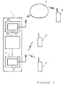
- the local radio telephone network shown comprises a base 1 comprising a set 11 of local communication circuits with terminals telephone 2, 3, here portable telephone sets.
- the set 11 includes radio circuits 9 for connection with homologous circuits of the terminals 2, 3, all here with DECT standard.
- the base 1 also includes a set 41 of circuits for connection with an external telephone network, set 41 which includes radio circuits 42 for connection with here the network of GSM cellular radiotelephony, referenced 4, to which a handset belongs radio telephone 5.
- a central microprocessor unit 10, comprising clock circuits, is connected to the various circuits to manage them.
- the local communication frequency, DECT is in the range extending from 1881 to 1897 MHz (fig. 3) and happens to be substantially double the frequency of the radio circuits 42 for connection to the GSM network 4, tuned in a range extending from 935 to 960 MHz.
- the frequency of the local communication radio circuits 9 is generated by a 12-18 frequency synthesizer (fig. 2) at lower frequency, controlling a frequency booster multiplier 20.
- the two circuits 12-18 and 20 above are easier to realize than a single oscillator which would be at the frequency aimed.
- the synthesizer produced 12-18 includes elements forming an antenna, it emits a spurious signal on its frequency.
- the downstream circuits do not completely eliminate, even after frequency multiplication (20) the original frequency component of synthesizer circuits 12-18.
- the radio circuits 9 and 42 being physically relatively close, it is avoided that the GSM 42 radio circuits, with high reception sensitivity in their range of GSM frequencies, receive and detect parasitic emissions from the synthesizer 12-18. Indeed, a communication can be established between one or more terminals 2, 3 and a terminal like that referenced 5 of the cellular network 4. It it is therefore a question of ensuring electromagnetic compatibility between the circuits radio circuits 9 and 42 which must be able to operate simultaneously.
- the synthesizer 12-18 is tuned to a frequency different from the frequency, or frequency range 935 - 960 MHz, of radio circuits 42 of link circuits 41.
- the frequency multiplier at output of synthesizer 12-18 has a multiplication ratio other than 2, with a determined margin.
- FIG. 2 shows in detail the local communication radio circuits 9.
- a PLL type oscillator circuit 12 (phase locked loop) connected to a control bus 40, is mounted in a control loop 13-18 and controls the frequency multiplier 20 providing the radio carrier transmission and reception of the time frame of the local DECT network.
- the synthesizer 12-18 comprises, from the output of the oscillator 12, a filter 13 low pass which feeds in parallel two oscillator circuits 14 and 15 of the VCO type, therefore voltage-controlled, which each control a amplifier 16 for loop output.
- Oscillator 15 is controlled by a modulation input of a data transmission channel to be transmitted locally by radio.
- the amplifier 16 controls a frequency predivisor circuit 17 controlling an amplifier 18 which controls the phase locked circuit 12.
- the output of amplifier 16 also controls, through an amplifier buffer 19, the frequency booster 20, here a tripler, the signal it generates is transmitted to the antenna 25 of the local network of the base 1 to through a coupler-derivator 21, a transmission amplifier 22, a switcher 23 transmit-receive and an antenna bandpass filter 24. Filter 24 is common to the transmission channel and the reception channel below.
- the tripler of frequency 20 therefore receives a signal (the leftmost in fig. 3) in the range 1881/3 - 1897/3, i.e. around 627 - 632 MHz, therefore outside the range GSM.
- the signals from the antenna 25 pass through the filter 24 and exit from the switch 23 by a specific channel connected to a low noise amplifier 26 followed by a low-pass filter 27 which feeds a mixer 28 for transposition of frequency also supplied by the signal derived from the coupler 21.
- the output of the mixer 28, low frequency passes through a low pass filter 29 then a limiter amplitude 30, automatic volume control.
- the limiter 30 supplies signals a demodulator 31 which is followed by a sampling circuit and hold 32 providing base 1 with digital baseband data of the DECT frame, coming from terminals 2, 3.
- the data to be transmitted locally by radio modulates the state of the oscillator circuit 15 and thus control the frequency of the signal from the tripler 20.
- the bus 40 makes it possible to choose one carrier among several in the DECT range.
- the bandpass filter 24 is also used for DECT transmission. It filters parasitic emissions likely to come from the 12-18 synthesizer which, although that granted outside the GSM range, could however present a spurious emission in a wide frequency band which, after multiplication (20), would cover the GSM range. This would be particularly the case if the 12-18 synthesizer operated substantially at a submultiple frequency whole of the GSM range, for example around 950/2 or 950/3 MHz. The first harmonics or partial of this frequency would then correspond to the GSM frequency range.
- GSM network 4 and link circuits 41 base 1 correspondents are replaced by the radiotelephony network DCS cellular and link circuits tuned in correspondence.
- the DCS transmission carrier is chosen from one of several channels in the 1710-1785 MHz range and that of reception, shown, in one channel among several in the 1805-1880 MHz range.
- the transmission and reception range DECT extending from 1881 to 1897 MHz, so there is only 1 MHz difference between the top of the DCS reception range and the bottom of the DECT range, which has ten channels at various frequencies spread across the range. Both ranges are therefore close.
- Curve F0 represents the level of the DECT emission spectrum, which overflows on the DCS range.
- central unit 10 does not allocate, for local communications DECT to establish, that channels of higher rank, i.e. inhibits channels whose frequency is located in the lateral portion of the DECT range located on the side of the DCS range, for example the portion of frequencies below 1890 MHz.
- the curve F1 corresponds to a frequency translation of the curve F0, representing the new, narrower spectrum, of DECT emission, at lower frequency limit shifted to high frequencies, after switching on out of service by inhibiting channels at the bottom of the DECT band, precisely those whose frequency distance to the DCS range is less than a value determined minimum threshold, here 10 MHz.
- a value determined minimum threshold here 10 MHz.
- Figure 4 shows that the upper limit of the useful part of the DCS range thus goes from 1850 to 1860 MHz, that is to say that the overflow DECT spectrum on the DCS range cannot be completely avoided.
- the central management unit 10 channels inhibits, in at least one of the ranges, the channels whose distance in frequency at the other range is less than a determined value, the value determined depending on the form of the emission spectrum of radio circuits DECT 9 and the emission level, as well as the sensitivity level of the circuits radio 42.
- Another alternative or complementary solution to protect reception cell DCS in base 1 against DECT emissions consists of performing high pass or band pass filtering of DECT emissions from circuits 9 by a filter like the antenna filter 24 to stiffen the lower edge of the spectrum DECT.
- the local communication radio circuits 9 include a filter range separator, frequency selectivity determined, and the unit central channel management 10 is arranged to inhibit a number of channels, cellular link radio circuits 42, a function of the selectivity of the filtered.
- the central unit 10 deactivates around 10 MHz in one or both of the DECT and DCS ranges, which corresponds to the selectivity of the filter, to attenuate, at a level below -109 dBm, the noise level of a DECT transmission carrier at 1881 MHz.
- the upper limit of the DCS range can be reduced to 1870 MHz instead of 1880 MHz, the DECT range being then unchanged or very little reduced at the bottom.
- Such a solution, limiting the DCS range has the advantage of offering up to 10 MHz of prohibited band between the two ranges, therefore allowing the use of a simple filter, without reducing excessively the relatively wide DCS range, which would not be the case for the DECT range.
- An even simpler filter, separating the two by 40 MHz ranges, would still be possible, with for example a DCS range limited to a maximum of 1850 MHz and a DECT range limited to a minimum of 1890 MHz.
- the number of channels inhibited is therefore a function of the filter selectivity.
Landscapes
- Engineering & Computer Science (AREA)
- Computer Networks & Wireless Communication (AREA)
- Signal Processing (AREA)
- Mobile Radio Communication Systems (AREA)
Abstract
Description
- la figure 1 est un schéma par blocs fonctionnels représentant le réseau téléphonique radio local de l'invention et un réseau de téléphonie cellulaire;
- la figure 2 est un schéma détaillé des circuits d'une base du réseau local;
- la figure 3 représente deux gammes de fréquences, locale et externe, et
- la figure 4 représente deux gammes de fréquences, locale et externe, dans le cas de la variante.
Claims (6)
- Base de réseau téléphonique local, comportant des moyens radio (9) de communication locale avec des terminaux téléphoniques (2, 3) et des moyens (41) de liaison avec un réseau téléphonique externe (4), caractérisée par le fait que les moyens de liaison (41) comportent des moyens radio (42) pour relier la base à un réseau de radiotéléphonie cellulaire (4).
- Base selon la revendication 1, dans laquelle la fréquence de communication locale est sensiblement le double de la fréquence des moyens radio (42) des moyens de liaison (41) avec le réseau téléphonique externe (4).
- Base selon la revendication 2, dans laquelle la fréquence des moyens radio de communication locale (9) est générée à partir d'une fréquence (12-18) différente de la fréquence desdits moyens radio (42) des moyens de liaison (41).
- Base selon l'une des revendications 1 à 3, dans laquelle les moyens radio de communication locale (9) comportent un filtre d'antenne (24) commun à une voie d'émission (22) et à une voie de réception (26).
- Base selon la revendication 1, dans laquelle, les moyens radio de communication locale (9) étant accordés sur des canaux d'une gamme de fréquences voisine d'une gamme de fréquences de canaux des moyens radio (42) de liaison cellulaire, il est prévu des moyens (10) de gestion des canaux pour inhiber, dans au moins une des gammes, les canaux dont la distance en fréquence à l'autre gamme est inférieure à une valeur déterminée.
- Base selon la revendication 5, dans laquelle les moyens radio de communication locale (9) comportent un filtre séparateur de gammes, de sélectivité en fréquence déterminée, et les moyens de gestion des canaux (10) sont agencés pour inhiber un nombre de canaux, des moyens radio (42) de liaison cellulaire, fonction de la sélectivité du filtre.
Applications Claiming Priority (2)
| Application Number | Priority Date | Filing Date | Title |
|---|---|---|---|
| FR9902945 | 1999-03-10 | ||
| FR9902945A FR2790902B1 (fr) | 1999-03-10 | 1999-03-10 | Base de reseau telephonique radio local reliee a un reseau de radiotelephonie cellulaire |
Publications (2)
| Publication Number | Publication Date |
|---|---|
| EP1037479A1 true EP1037479A1 (fr) | 2000-09-20 |
| EP1037479B1 EP1037479B1 (fr) | 2006-10-11 |
Family
ID=9543012
Family Applications (1)
| Application Number | Title | Priority Date | Filing Date |
|---|---|---|---|
| EP20000400629 Expired - Lifetime EP1037479B1 (fr) | 1999-03-10 | 2000-03-08 | Base de réseau radiotéléphonique local reliée à un réseau de radiotéléphonie cellulaire |
Country Status (4)
| Country | Link |
|---|---|
| EP (1) | EP1037479B1 (fr) |
| DE (1) | DE60031192T2 (fr) |
| ES (1) | ES2273654T3 (fr) |
| FR (1) | FR2790902B1 (fr) |
Citations (3)
| Publication number | Priority date | Publication date | Assignee | Title |
|---|---|---|---|---|
| DE2937018A1 (de) * | 1979-09-13 | 1981-04-02 | TE KA DE Felten & Guilleaume Fernmeldeanlagen GmbH, 8500 Nürnberg | Verfahren zur kanalzuteilung |
| US5349694A (en) * | 1990-08-22 | 1994-09-20 | Mitsubishi Denki Kabushiki Kaisha | Radio relay system with a multiplex separation circuit and control for providing time delay multiplex operation of receiver and transmitter |
| EP0849965A1 (fr) * | 1996-12-20 | 1998-06-24 | E-Plus Mobilfunk GmbH | Téléphone sans fil |
-
1999
- 1999-03-10 FR FR9902945A patent/FR2790902B1/fr not_active Expired - Fee Related
-
2000
- 2000-03-08 EP EP20000400629 patent/EP1037479B1/fr not_active Expired - Lifetime
- 2000-03-08 DE DE2000631192 patent/DE60031192T2/de not_active Expired - Lifetime
- 2000-03-08 ES ES00400629T patent/ES2273654T3/es not_active Expired - Lifetime
Patent Citations (3)
| Publication number | Priority date | Publication date | Assignee | Title |
|---|---|---|---|---|
| DE2937018A1 (de) * | 1979-09-13 | 1981-04-02 | TE KA DE Felten & Guilleaume Fernmeldeanlagen GmbH, 8500 Nürnberg | Verfahren zur kanalzuteilung |
| US5349694A (en) * | 1990-08-22 | 1994-09-20 | Mitsubishi Denki Kabushiki Kaisha | Radio relay system with a multiplex separation circuit and control for providing time delay multiplex operation of receiver and transmitter |
| EP0849965A1 (fr) * | 1996-12-20 | 1998-06-24 | E-Plus Mobilfunk GmbH | Téléphone sans fil |
Also Published As
| Publication number | Publication date |
|---|---|
| DE60031192T2 (de) | 2007-08-23 |
| FR2790902A1 (fr) | 2000-09-15 |
| FR2790902B1 (fr) | 2001-04-20 |
| DE60031192D1 (de) | 2006-11-23 |
| ES2273654T3 (es) | 2007-05-16 |
| EP1037479B1 (fr) | 2006-10-11 |
Similar Documents
| Publication | Publication Date | Title |
|---|---|---|
| US6954628B2 (en) | Radio receiver | |
| EP1524777B1 (fr) | Émetteur-récepteur sur une puce | |
| JP4339509B2 (ja) | 無線通信ネットワークにおける方法および装置 | |
| US6978125B2 (en) | Methods and apparatus for tuning pre-selection filters in radio receivers | |
| EP1241779A2 (fr) | Récepteur à multiples porteuses | |
| US6415001B1 (en) | System and process for shared frequency source multi-band transmitters and receivers | |
| US7116965B2 (en) | Radio receiver | |
| FR2810173A1 (fr) | Dispositif d'emission et/ou de reception radiofrequence | |
| US8238858B2 (en) | Communication device, multi-band receiver, and receiver | |
| US20020151287A1 (en) | Receiver front-end filter tuning | |
| FR2897215A1 (fr) | Dispositif et procede d'annulation des interferences | |
| FR2786056A1 (fr) | Procede de reglage d'un emetteur recepteur multibande de telephonie mobile et telephone mobile ainsi obtenu | |
| US7031748B2 (en) | Radio signal receiving apparatus and demodulating circuit | |
| KR101053136B1 (ko) | 공유 기능 블록 멀티 모드 멀티 밴드 통신 트랜시버 | |
| US7680476B2 (en) | Receiving device | |
| EP1037479B1 (fr) | Base de réseau radiotéléphonique local reliée à un réseau de radiotéléphonie cellulaire | |
| EP1052772B1 (fr) | Dispositif et procédé pour produire un signal filtré | |
| FR2828624A1 (fr) | Systeme d'emission/reception pour telephone mobile multibande et multimode | |
| JP2006526914A (ja) | 周波数変調信号の受信器及び送信器 | |
| KR100259058B1 (ko) | 통신시스템의 혼변조신호 처리장치 및 방법 | |
| JP3134801B2 (ja) | 共用受信機 | |
| JP4696868B2 (ja) | 受信装置および受信方法 | |
| FR2828626A1 (fr) | Systeme d'emission/reception pour telephone mobile multibande et multimode | |
| FR2802757A1 (fr) | Recepteur a rejection d'image dans un telephone mobile et son procede associe | |
| EP0989682A1 (fr) | Emetteur récepteur de téléphonie mobile |
Legal Events
| Date | Code | Title | Description |
|---|---|---|---|
| PUAI | Public reference made under article 153(3) epc to a published international application that has entered the european phase |
Free format text: ORIGINAL CODE: 0009012 |
|
| AK | Designated contracting states |
Kind code of ref document: A1 Designated state(s): DE ES FR GB IT |
|
| AX | Request for extension of the european patent |
Free format text: AL;LT;LV;MK;RO;SI |
|
| 17P | Request for examination filed |
Effective date: 20010316 |
|
| AKX | Designation fees paid |
Free format text: DE ES FR GB IT |
|
| 17Q | First examination report despatched |
Effective date: 20050301 |
|
| GRAP | Despatch of communication of intention to grant a patent |
Free format text: ORIGINAL CODE: EPIDOSNIGR1 |
|
| RAP1 | Party data changed (applicant data changed or rights of an application transferred) |
Owner name: SAGEM COMMUNICATION |
|
| GRAS | Grant fee paid |
Free format text: ORIGINAL CODE: EPIDOSNIGR3 |
|
| GRAA | (expected) grant |
Free format text: ORIGINAL CODE: 0009210 |
|
| AK | Designated contracting states |
Kind code of ref document: B1 Designated state(s): DE ES FR GB IT |
|
| REG | Reference to a national code |
Ref country code: GB Ref legal event code: FG4D Free format text: NOT ENGLISH |
|
| REF | Corresponds to: |
Ref document number: 60031192 Country of ref document: DE Date of ref document: 20061123 Kind code of ref document: P |
|
| GBT | Gb: translation of ep patent filed (gb section 77(6)(a)/1977) |
Effective date: 20070111 |
|
| REG | Reference to a national code |
Ref country code: ES Ref legal event code: FG2A Ref document number: 2273654 Country of ref document: ES Kind code of ref document: T3 |
|
| PLBE | No opposition filed within time limit |
Free format text: ORIGINAL CODE: 0009261 |
|
| STAA | Information on the status of an ep patent application or granted ep patent |
Free format text: STATUS: NO OPPOSITION FILED WITHIN TIME LIMIT |
|
| 26N | No opposition filed |
Effective date: 20070712 |
|
| REG | Reference to a national code |
Ref country code: GB Ref legal event code: 732E Free format text: REGISTERED BETWEEN 20090326 AND 20090401 |
|
| REG | Reference to a national code |
Ref country code: FR Ref legal event code: TP |
|
| REG | Reference to a national code |
Ref country code: FR Ref legal event code: TP Owner name: SAGEMCOM BROADBAND SAS, FR Effective date: 20111215 |
|
| REG | Reference to a national code |
Ref country code: DE Ref legal event code: R082 Ref document number: 60031192 Country of ref document: DE Representative=s name: BOEHMERT & BOEHMERT, DE |
|
| REG | Reference to a national code |
Ref country code: DE Ref legal event code: R081 Ref document number: 60031192 Country of ref document: DE Owner name: SAGEMCOM SAS, FR Free format text: FORMER OWNER: SAGEM COMMUNICATION, PARIS, FR Effective date: 20120507 Ref country code: DE Ref legal event code: R082 Ref document number: 60031192 Country of ref document: DE Representative=s name: BOEHMERT & BOEHMERT, DE Effective date: 20120507 Ref country code: DE Ref legal event code: R082 Ref document number: 60031192 Country of ref document: DE Representative=s name: BOEHMERT & BOEHMERT ANWALTSPARTNERSCHAFT MBB -, DE Effective date: 20120507 |
|
| REG | Reference to a national code |
Ref country code: DE Ref legal event code: R082 Ref document number: 60031192 Country of ref document: DE Representative=s name: BOEHMERT & BOEHMERT, DE |
|
| REG | Reference to a national code |
Ref country code: DE Ref legal event code: R082 Ref document number: 60031192 Country of ref document: DE Representative=s name: BOEHMERT & BOEHMERT, DE Effective date: 20130129 Ref country code: DE Ref legal event code: R081 Ref document number: 60031192 Country of ref document: DE Owner name: SAGEMCOM SAS, FR Free format text: FORMER OWNER: SAGEM TELECOMMUNICATIONS S. A., PARIS, FR Effective date: 20130129 Ref country code: DE Ref legal event code: R082 Ref document number: 60031192 Country of ref document: DE Representative=s name: BOEHMERT & BOEHMERT ANWALTSPARTNERSCHAFT MBB -, DE Effective date: 20130129 |
|
| REG | Reference to a national code |
Ref country code: FR Ref legal event code: PLFP Year of fee payment: 16 |
|
| REG | Reference to a national code |
Ref country code: FR Ref legal event code: PLFP Year of fee payment: 17 |
|
| REG | Reference to a national code |
Ref country code: FR Ref legal event code: TP Owner name: SAGEMCOM BROADBAND SAS, FR Effective date: 20160727 Ref country code: FR Ref legal event code: CD Owner name: SAGEMCOM BROADBAND SAS, FR Effective date: 20160727 |
|
| REG | Reference to a national code |
Ref country code: FR Ref legal event code: PLFP Year of fee payment: 18 |
|
| REG | Reference to a national code |
Ref country code: FR Ref legal event code: PLFP Year of fee payment: 19 |
|
| PGFP | Annual fee paid to national office [announced via postgrant information from national office to epo] |
Ref country code: IT Payment date: 20180219 Year of fee payment: 19 |
|
| PGFP | Annual fee paid to national office [announced via postgrant information from national office to epo] |
Ref country code: ES Payment date: 20180403 Year of fee payment: 19 |
|
| PGFP | Annual fee paid to national office [announced via postgrant information from national office to epo] |
Ref country code: DE Payment date: 20190219 Year of fee payment: 20 Ref country code: GB Payment date: 20190222 Year of fee payment: 20 |
|
| PGFP | Annual fee paid to national office [announced via postgrant information from national office to epo] |
Ref country code: FR Payment date: 20190220 Year of fee payment: 20 |
|
| PG25 | Lapsed in a contracting state [announced via postgrant information from national office to epo] |
Ref country code: IT Free format text: LAPSE BECAUSE OF NON-PAYMENT OF DUE FEES Effective date: 20190308 |
|
| REG | Reference to a national code |
Ref country code: DE Ref legal event code: R071 Ref document number: 60031192 Country of ref document: DE |
|
| REG | Reference to a national code |
Ref country code: GB Ref legal event code: PE20 Expiry date: 20200307 |
|
| PG25 | Lapsed in a contracting state [announced via postgrant information from national office to epo] |
Ref country code: GB Free format text: LAPSE BECAUSE OF EXPIRATION OF PROTECTION Effective date: 20200307 |
|
| REG | Reference to a national code |
Ref country code: ES Ref legal event code: FD2A Effective date: 20200724 |
|
| PG25 | Lapsed in a contracting state [announced via postgrant information from national office to epo] |
Ref country code: ES Free format text: LAPSE BECAUSE OF NON-PAYMENT OF DUE FEES Effective date: 20190309 |