EP1037401B1 - Verminderung von falschem Empfang auf einem Nebenkanal auf einer Aufwärtsverbindung in einer Kommunikationsanordnung mit datenverarbeitenden Satelliten durch Verschlüsselungssequenzen - Google Patents
Verminderung von falschem Empfang auf einem Nebenkanal auf einer Aufwärtsverbindung in einer Kommunikationsanordnung mit datenverarbeitenden Satelliten durch Verschlüsselungssequenzen Download PDFInfo
- Publication number
- EP1037401B1 EP1037401B1 EP00104578A EP00104578A EP1037401B1 EP 1037401 B1 EP1037401 B1 EP 1037401B1 EP 00104578 A EP00104578 A EP 00104578A EP 00104578 A EP00104578 A EP 00104578A EP 1037401 B1 EP1037401 B1 EP 1037401B1
- Authority
- EP
- European Patent Office
- Prior art keywords
- uplink
- data
- decoder
- scrambling sequence
- communication apparatus
- Prior art date
- Legal status (The legal status is an assumption and is not a legal conclusion. Google has not performed a legal analysis and makes no representation as to the accuracy of the status listed.)
- Expired - Lifetime
Links
Images


Classifications
-
- H—ELECTRICITY
- H04—ELECTRIC COMMUNICATION TECHNIQUE
- H04B—TRANSMISSION
- H04B7/00—Radio transmission systems, i.e. using radiation field
- H04B7/14—Relay systems
- H04B7/15—Active relay systems
- H04B7/185—Space-based or airborne stations; Stations for satellite systems
- H04B7/1851—Systems using a satellite or space-based relay
- H04B7/18513—Transmission in a satellite or space-based system
Definitions
- the present invention relates to mitigation of false co-channel uplink reception (also known as "show-thru") in a satellite communication system.
- the present invention relates to the application of cover sequences at earth terminals that allows a receiving satellite to reliably discard show-thru signals.
- a multi-beam processing satellite system may transmit and receive numerous beams distinguished by the frequency and polarization of the signals present in the beam.
- the same frequency, same polarization beams i.e., the same "color" beams
- Beam reuse renders the same color beams susceptible to co-channel interference such that a portion of the signal from a beam B is observed in a beam A.
- co-channel interference arises primarily because of the practical limitations in implementing an antenna system which, ideally, would provide perfect rejection of same-color signals from other than the desired beam.
- the coverage provided for beam A inevitably provides some response to signals originating in beam B due to real world limitations in the physical realization of the antenna system.
- 12 to 16, or more beams of the same color may be reused over a coverage area, correspondingly increasing the potential for CCI.
- Processing satellite systems may further employ TDMA (time division multiple access) techniques that permit several user earth terminals to time share a frequency channel by sending short traffic bursts in assigned time slots. These bursts typically exploit powerful error correcting codes to ensure the integrity of the traffic being carried. However, when the time slots in two same-color beams, A & B, are time aligned, a phenomenon known as show-thru may occur.
- TDMA time division multiple access
- show-thru may occur in beam A when no burst is present in a slot in beam A but a burst is present in the matching channel and slot in beam B.
- the burst from beam B couples (albeit in attenuated form) into the receiving electronics for beam A.
- the signal to noise ratio of this inadvertently coupled signal may be quite low, the error correcting code applied to the burst in beam B improves the likelihood that the burst from B will be regarded as valid by the processor for beam A.
- each mobile station has a unique cipher key associated therewith and enciphers speech information using the cipher key which is subsequently combined with a spread spectrum mask code unique to the mobile station.
- Another object of the present invention is to provide a simple and effective method of reliably discarding show-thru signals at a receiver.
- the method includes the steps of selecting a scrambling sequence A and selecting a scrambling sequence B differing from the scrambling sequence A. The method then applies the scrambling sequence A to uplink A data to form scrambled uplink A data and further applies the scrambling sequence B to uplink B data to form scrambled uplink B data.
- the uplink A and the uplink B are thereby differentiated and have vastly improved resistance to show-thru.
- the scrambled uplink A data and the scrambled uplink B data are then transmitted to a receiver, for example, onboard a satellite.
- the method also codes the uplink A data and the uplink B data prior to scrambling.
- the coding in general, applies an error correcting code capable of correcting T errors.
- the scrambling sequence B differs from the scrambling sequence A in more than T locations to prevent a decoder for uplink A from correcting errors generated in the decoder by scrambling sequence B.
- the method is generally applicable to numerous same color uplink beams in a coverage area.
- the method may operate on additional uplink beams, for example, an uplink beam C.
- the method selects a scrambling sequence C differing from the other scrambling sequences.
- the uplink C data is then coded and the scrambling sequence C is applied.
- the resultant uplink beam C thereby benefits from increased resistance to show-thru from uplink beams A and B, uplink B resists show-thru from uplink beams A and C, and uplink A resists show-thru from uplink beams B and C.
- the method may use an exclusive-or operation.
- Figure 1 illustrates a satellite cellular communication system 100 including a frequency reuse plan 102 generated by a satellite 104.
- the frequency reuse plan 102 may make use of multiple frequencies and polarizations (for example, differently colored beams A and B in Figure 1) to reduce interference between cells.
- the reuse plan 102 includes multiple cells 106-112, for example, that correspond to spot beams separately produced (as downlinks) and received (as uplinks) by the satellite 104 and user earth terminals (UETs) present in the cells 106-112.
- Figure 1 shows that multiple identically colored beams may exist in the frequency reuse plan 102.
- the cells 106 (supported by beam A) and 110 (supported by beam B) share the same color and are therefore candidates for CCI and show-thru.
- the cells 114-122 all share the same color as the cells 108 and 110.
- the discussion below proceeds with reference to beams A and B, it is noted that the techniques discussed below are also applicable to numerous additional same color beams in any frequency reuse plan.
- the communication system 200 includes an uplink A encoder 202 for a UET generating an uplink A 204, and an uplink B encoder 206 for a UET generating an uplink B 208.
- the transmission channel 210 as well as an uplink A decoder 212 and a gate circuit 214 are also shown in Figure 2.
- the uplink A decoder 212 may accurately decode the received uplink A signal.
- the received uplink A signal may still include errors, possibly generated from CCI due to the uplink B signals.
- the signal received is substantially that of the uplink A, possibly tainted by CCI or other interference.
- the uplink A decoder 212 in general, decodes the coding applied by the uplink A coder 202, which may, for example, apply a (236, 212) Reed-Solomon code, BCH code, or other error correcting code. Beyond T errors, however, the decoder 212 cannot correct the received uplink signals and asserts a "decoder failure."
- the gate circuitry 214 generally is responsive to the uplink A decoder 212 and its assertions or non-assertions of decoder failure. Thus, for example, the gate circuitry 214 may pass the decoded uplink signals to subsequent processing elements or discard the decoded uplink signals (upon decoder failure).
- the uplink A encoder 202, uplink A decoder 212, or gate circuitry 214 may be created using combinatorial logic, ASICs, through software executed by a CPU, a DSP chip, or the like.
- the foregoing elements may be part of hardware that is used to perform other operational functions at a UET or a satellite.
- the uplink A decoder 212 will occasionally succeed in correcting the weak signal from B due to the effective error correcting code applied on all uplink signals. Because the actual receiver and decoder for the uplink A 204 are unaware that the weak signal originated in another beam, a correctly decoded data from the uplink B 208 is periodically recovered and considered part of the uplink A 204 data stream. Thus, in the case where ATM cells are transmitted, a cell misinsertion results, and in general the privacy of the uplink B data is compromised. The frequency of occurrence of show-thru, although small, may be orders of magnitude higher than is acceptable to meet the Cell Misinsertion Ratio (CMR) criteria of an ATM system.
- CMR Cell Misinsertion Ratio
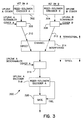
- the communication system 300 includes an uplink A coder 302, an uplink B coder 304, an uplink A scrambler 306, and an uplink B scrambler 308.
- the uplink A 310, uplink B 312, and the communication channel 314 are also illustrated. Included at a receiver intended for the uplink A 310 is an uplink A descrambler 316, an uplink A decoder 318, and a gate circuit 320.
- the uplink A coder 302, uplink B coder 304, uplink A decoder 318, and gate circuit 320 function substantially as described above with respect to the corresponding elements of Figure 2. Note the introduction, however, of the uplink A scrambler 306 and the uplink B scrambler 308. As will be described in more detail below, the scrambling sequences applied to the uplink data will provide increased resistance to show-thru in the communications system 300.
- the uplink A scrambler 306 applies a cover sequence or scrambling sequence A to uplink A data
- the uplink B scrambler 308 applies a scrambling sequence B to uplink B data.
- any of the uplink data may be subjected to additional coding including inner coding to form a concatenated code.
- the scramblers 306 and 308, as well as the descrambler 318 may, for example, be implemented as exclusive-or circuitry (or software) that XORs a scrambling sequence with uplink data.
- the scrambling sequences thereby add no extra overhead information to the uplink data, but provide increased resistance to show-thru as explained below.
- the scrambling sequences are chosen to have a small cross-correlation between any two sequences for different same-color beams.
- portions of different phases of the same maximal length (ML) sequence i.e. cyclic shifts of the same underlying ML sequence
- each scrambling sequence preferably differs from each other scrambling sequence in more than T locations (i.e., the minimum distance between scrambling sequences should be greater than T) to prevent, for example, an uplink A decoder from correcting scrambled uplink B data.
- the scrambled uplink A data is transmitted through the channel 314 to a satellite.
- the scrambled A data (including transmission errors due to noise, CCI, and other effects), is descrambled by the uplink A descrambler 316.
- the uplink A descrambler 316 may descramble the uplink A data by exclusive-oring the scrambling sequence A (applied at the UET) with the received uplink A signal.
- the resultant descrambled uplink A data is then presented to the uplink A decoder 318.
- the scramblers 306, 308 provide a vast reduction in the likelihood of show-thru.
- the scrambling sequence B differs in, preferably, more than T positions from the scrambling sequence A.
- the uplink A descrambler 318 in applying the scrambling sequence A, creates a large number of apparent errors in the descrambled data presented to the uplink A decoder 318.
- the probability of correct decoding for an uplink signal having many errors is very small.
- the uplink A decoder 318 during show-thru, asserts decoder failure, in which case the show-thru uplink signal is discarded by the gate circuit 320.
- show-thru uplink signals are rejected by the uplink A receiver electronics and, for example, misinsertion is prevented and the integrity of the uplink B data is preserved.
- a potential show-thru block will reach the uplink A decoder 318 with most of its 236 (byte) symbols in error because of being uncovered by the scrambling sequence A rather than the scrambling sequence B.
- the probability that the uplink A decoder 318 will not assert decoder failure when presented with a large number of apparent errors is less than one part per billion, consistent with typical requirements for CMR.
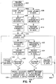
- FIG 400 shows a high level flow diagram 400 of one implementation of the present invention.
- the diagram 400 generally shows the steps performed on the ground, including a providing step 402, coding steps 404, 406, scrambling steps 408, 410, and transmission steps 412, 414.
- the diagram 400 also shows the steps occurring at a receiver, for example, a satellite, including a receiving step 416, descrambling steps 418, 420, decoding steps 422, 424, and decoder decisions steps 426, 428. Discarding steps 430, 432, and retransmission steps 434 and 436 are also illustrated.
- scrambling sequences are provided for each same color uplink beam, for example, using predetermined or shift register produced ML sequences.
- the providing step 403 may occur, for example, at a Network Operation and Control Center (NOC), which may then distribute scrambling sequences to individual UETs.
- NOC Network Operation and Control Center
- one or more UETs encode uplink A data and uplink B data, for example using a Reed-Solomon code, optionally followed by an inner code.
- a scrambling sequence A is applied to the coded uplink A data and a scrambling sequence B is applied to the coded uplink B data.
- the scrambled uplink A and B data are transmitted in an uplink A and an uplink B at steps 412 and 414, respectively.
- the receiver receives one or more of the uplinks A and B at step 416.
- the received uplink A and B signals are subjected to demodulation and additional processing (not shown) to generate baseband uplink A data and uplink B data.
- the received uplink A data and the received uplink B data are descrambled at steps 418 and 420, respectively.
- the scrambling sequences A and B applied at steps 408 and 410 may be reapplied using a reversible process (e.g., an exclusive-or circuit).
- the resultant descrambled A and B data are applied to decoders at the decoding steps 422 and 424 which generate decoded A data and decoded B data, respectively.
- decoder failure results with very high probability during show-thru (and, in general, whenever more than T errors are present in the data input to the decoder).
- the receiver checks for decoder failure, and if asserted, discards the decoded A or B data. Processing continues at the reception step 416.
- the absence of decoder failure is an extremely good indication that, as the case may be, the decoded A data or the decoded B data is correct data intended to be received by the uplink A receiver or the uplink B receiver.
- the resultant correct decoded A data may be switched, recoded, remodulated, and retransmitted to any appropriate destination.
- the resultant correct decoded B data may be switched, recoded, remodulated, and retransmitted to any appropriate destination.
- the present invention may be efficiently implemented in practice because multiple variants of an ML sequence, or a portion thereof, may all be produced from the same shift register by changing only the starting state.
- the encoder at the UET e.g., the uplink A encoder 302
- the matching decoders e.g., the uplink A decoder 318, at the satellite are commonly present in modern satellite communications systems and blend seamlessly with the scrambling and descrambling of the present invention.
Landscapes
- Engineering & Computer Science (AREA)
- Physics & Mathematics (AREA)
- Astronomy & Astrophysics (AREA)
- Aviation & Aerospace Engineering (AREA)
- General Physics & Mathematics (AREA)
- Computer Networks & Wireless Communication (AREA)
- Signal Processing (AREA)
- Radio Relay Systems (AREA)
- Error Detection And Correction (AREA)
- Detection And Prevention Of Errors In Transmission (AREA)
- Synchronisation In Digital Transmission Systems (AREA)
- Mobile Radio Communication Systems (AREA)
Claims (9)
- Verfahren zum Verarbeiten von Aufwärtssignalen an einer Aufwärtskommunikationsvorrichtung (300) eines Satellitenempfängers (104) mit einem Dekodierer, der in der Lage ist, bis zu T Fehler in einem gegebenen Aufwärtssignal zu korrigieren, wobei das Verfahren umfasst:Empfangen von an der Aufwärtskommunikationsvorrichtung (300) vorhandenen Aufwärtssignalen (A), die abhängig von einer aus einer Vielzahl von Scramblefolgen gescrambelt worden sind, von denen sich jede von den anderen an mehr als T Stellen unterscheidet;Entscrambeln der Aufwärtssignale (A) unter Verwendung eines Entscramblers (316), welcher eine vorbestimmte Scramblefolge ausnutzt, die gültigen Aufwärtssignalen zugeordnet ist, welche nur für diese Aufwärtskommunikationsvorrichtung (300) vorgesehen ist;Dekodieren des entscrambleten Signals unter Verwendung eines Dekodierers (318), der in der Lage ist, bis zu T darin enthaltene Fehler zu korrigieren, so dass jedes empfangene Signal, das ursprünglich abhängig von einer anderen Scramblefolge gescrambelt worden ist, mehr als T Fehler aufweist, wodurch sich ein Dekodiererfehler ergibt;Erzeugen eines Dekodiererfehlersignals, falls ein Fehler beim Dekodieren durch den Dekodierer (318) erkannt wird; undÜbertragen (434, 436) des dekodierten Signals auf der Abwärtsverbindung mittels der Aufwärtskommunikationsvorrichtung (300) der Satellitenempfängers (104), falls das Dekodiererfehlersignal nicht bestätigt wird.
- Verfahren nach einem der vorhergehenden Ansprüche, wobei der Schritt des Dekodierens ein Durchführen eines Dekodierens nach Reed-Solomon umfasst.
- Verfahren nach einem der vorhergehenden Ansprüche, wobei der Schritt des Dekodierens ein Dekodieren mit einem (236,212)-Reed-Solomon-Code umfasst.
- Verfahren nach einem der vorhergehenden Ansprüche, weiterhin umfassend den anfänglichen Schritt des Erzeugens einer eindeutigen Scramblefolge für jedes aus einer Vielzahl von Aufwärtssignalen der gleichen Farbe aufgrund eines vorbestimmten Wiederverwendungsmusters.
- Verfahren nach einem der vorhergehenden Ansprüche, wobei der Schritt des Entscrambelns der Aufwärtssignale (A) den Schritt eines 'exklusiv-ODER'-Verknüpfens der Aufwärtssignale (A) mit der Scramblefolge umfasst, die gültigen Aufwärtssignalen zugeordnet ist, die für den Aufwärtsempfänger (300) vorgesehen sind.
- Satelliten-Aufwärtskommunikationsvorrichtung (300) in einem Satellitenempfänger (104) zum Verarbeiten von Aufwärtssignalen (A), die abhängig von einer aus einer Vielzahl von Scramblefolgen gescrambelt worden sind, von denen sich jede von den anderen an mehr als T Stellen unterscheidet, wobei die Kommunikationsvorrichtung umfasst:einen Entscrambler (316), der eingerichtet ist, von der Aufwärtskommunikationsvorrichtung (300) empfangene Aufwärtssignale (A) durch Ausnutzen einer Scramblefolge zu entscrambeln, welche gültigen Aufwärtssignalen (A) zugeordnet ist, die nur für diese Aufwärtskommunikationsvorrichtung (300) vorgesehen sind; undeinen Dekodierer (318), der in der Lage ist, bis zu T darin enthaltene Fehler zu korrigieren, um das entscrambelte Signal zu dekodieren, so dass jedes empfangene Signal, das ursprünglich abhängig von einer anderen Scramblefolge gescrambelt worden ist, mehr als T Fehler aufweisen sollte, wodurch sich ein Dekodierfehler ergibt, wobei der Dekodierer (318) eingerichtet ist, ein Dekodiererfehlersignal zu erzeugen, falls ein Fehler beim Dekodieren erkannt wird, wobei die Satelliten-Aufwärtskommunikationsvorrichtung (300) eingerichtet ist, das dekodierte Signal auf der Abwärtsverbindung zu übertragen, falls das Dekodiererfehlersignal nicht bestätigt ist.
- Satelliten-Aufwärtskommunikationsvorrichtung nach Anspruch 6, wobei der Dekodierer (318) ein Reed-Solomon-Dekodierer ist.
- Satelliten-Aufwärtskommunikationsvorrichtung nach Anspruch 6 oder 7, wobei der Dekodierer (318) ein (236,212)-Reed-Solomon-Dekodierer ist.
- Satelliten-Aufwärtskommunikationsvorrichtung nach einem der Ansprüche 6 bis 8, wobei der Entscrambler (316) eine 'exklusiv-ODER'-Schaltung zum Kombinieren von Aufwärtssignalen (A) mit der Scramblefolge verwendet, um die Aufwärtssignale zu entscrambelt.
Applications Claiming Priority (2)
| Application Number | Priority Date | Filing Date | Title |
|---|---|---|---|
| US270567 | 1999-03-16 | ||
| US09/270,567 US6707916B1 (en) | 1999-03-16 | 1999-03-16 | Mitigation of false co-channel uplink reception in a processing satellite communication system using scrambling sequences |
Publications (3)
| Publication Number | Publication Date |
|---|---|
| EP1037401A2 EP1037401A2 (de) | 2000-09-20 |
| EP1037401A3 EP1037401A3 (de) | 2003-05-07 |
| EP1037401B1 true EP1037401B1 (de) | 2006-05-31 |
Family
ID=23031836
Family Applications (1)
| Application Number | Title | Priority Date | Filing Date |
|---|---|---|---|
| EP00104578A Expired - Lifetime EP1037401B1 (de) | 1999-03-16 | 2000-03-14 | Verminderung von falschem Empfang auf einem Nebenkanal auf einer Aufwärtsverbindung in einer Kommunikationsanordnung mit datenverarbeitenden Satelliten durch Verschlüsselungssequenzen |
Country Status (6)
| Country | Link |
|---|---|
| US (1) | US6707916B1 (de) |
| EP (1) | EP1037401B1 (de) |
| JP (1) | JP3476735B2 (de) |
| AT (1) | ATE328405T1 (de) |
| CA (1) | CA2300672A1 (de) |
| DE (1) | DE60028274T2 (de) |
Families Citing this family (16)
| Publication number | Priority date | Publication date | Assignee | Title |
|---|---|---|---|---|
| US6993288B2 (en) * | 2002-07-17 | 2006-01-31 | The Boeing Company | Managing satellite fixed beam uplink using virtual channel assignments |
| US8358971B2 (en) | 2002-07-23 | 2013-01-22 | Qualcomm Incorporated | Satellite-based programmable allocation of bandwidth for forward and return links |
| US7379758B2 (en) * | 2002-07-23 | 2008-05-27 | Qualcomm Incorporated | Satellite communication system constituted with primary and back-up multi-beam satellites |
| US20060060333A1 (en) * | 2002-11-05 | 2006-03-23 | Lalit Chordia | Methods and apparatuses for electronics cooling |
| US7525934B2 (en) * | 2003-09-24 | 2009-04-28 | Qualcomm Incorporated | Mixed reuse of feeder link and user link bandwidth |
| US8213553B2 (en) * | 2004-04-12 | 2012-07-03 | The Directv Group, Inc. | Method and apparatus for identifying co-channel interference |
| US7672285B2 (en) * | 2004-06-28 | 2010-03-02 | Dtvg Licensing, Inc. | Method and apparatus for minimizing co-channel interference by scrambling |
| US7161988B2 (en) * | 2004-04-12 | 2007-01-09 | The Directv Group, Inc. | Method and apparatus for minimizing co-channel interference |
| WO2005101839A2 (en) * | 2004-04-12 | 2005-10-27 | The Directv Group, Inc. | Shifted channel characteristics for mitigating co-channel interference |
| JP5080470B2 (ja) * | 2005-08-26 | 2012-11-21 | ザ・ディレクティービー・グループ・インコーポレイテッド | 信号送信のためのスクランブリングコードを決定する方法と装置 |
| WO2008060759A2 (en) * | 2006-10-03 | 2008-05-22 | Viasat, Inc. | Map-trigger dump of packets in satellite communication system |
| EP2084831A2 (de) * | 2006-10-03 | 2009-08-05 | ViaSat, Inc. | Grosspaketverkettung in einem satellitenkommunikationssystem |
| CN101573891A (zh) * | 2006-10-03 | 2009-11-04 | 维尔塞特公司 | 卫星通信系统中最前面延时的串接 |
| CN101573889B (zh) * | 2006-10-03 | 2014-05-14 | 维尔塞特公司 | 卫星通信系统中上行数据流资源的Web/成批传送预分配 |
| US7869759B2 (en) * | 2006-12-14 | 2011-01-11 | Viasat, Inc. | Satellite communication system and method with asymmetric feeder and service frequency bands |
| FR2937201B1 (fr) * | 2008-10-10 | 2011-11-25 | Thales Sa | Procede de protection selective de la rediffusion par satellite de donnees diffusee publiquement et collectees par le satellite |
Family Cites Families (6)
| Publication number | Priority date | Publication date | Assignee | Title |
|---|---|---|---|---|
| US4178550A (en) | 1977-06-03 | 1979-12-11 | Bell Telephone Laboratories, Incorporated | Method and apparatus to permit substantial cancellation of interference between a received first and second signal |
| US4860352A (en) * | 1985-05-20 | 1989-08-22 | Satellite Financial Systems Corporation | Satellite communication system and method with message authentication suitable for use in financial institutions |
| US5113443A (en) * | 1987-07-17 | 1992-05-12 | Brockman Milton H | Method for scrambling satellite communications |
| JPH04283885A (ja) * | 1991-03-13 | 1992-10-08 | Alps Electric Co Ltd | 自動識別デコード装置 |
| US5550809A (en) * | 1992-04-10 | 1996-08-27 | Ericsson Ge Mobile Communications, Inc. | Multiple access coding using bent sequences for mobile radio communications |
| JPH09172685A (ja) * | 1995-12-19 | 1997-06-30 | Sony Corp | 無線通信システム及び通信方法並びに移動通信端末装置 |
-
1999
- 1999-03-16 US US09/270,567 patent/US6707916B1/en not_active Expired - Lifetime
-
2000
- 2000-03-14 DE DE60028274T patent/DE60028274T2/de not_active Expired - Fee Related
- 2000-03-14 CA CA002300672A patent/CA2300672A1/en not_active Abandoned
- 2000-03-14 AT AT00104578T patent/ATE328405T1/de not_active IP Right Cessation
- 2000-03-14 EP EP00104578A patent/EP1037401B1/de not_active Expired - Lifetime
- 2000-03-15 JP JP2000072193A patent/JP3476735B2/ja not_active Expired - Fee Related
Also Published As
| Publication number | Publication date |
|---|---|
| JP3476735B2 (ja) | 2003-12-10 |
| DE60028274T2 (de) | 2006-11-02 |
| DE60028274D1 (de) | 2006-07-06 |
| EP1037401A3 (de) | 2003-05-07 |
| EP1037401A2 (de) | 2000-09-20 |
| CA2300672A1 (en) | 2000-09-16 |
| US6707916B1 (en) | 2004-03-16 |
| JP2000312171A (ja) | 2000-11-07 |
| ATE328405T1 (de) | 2006-06-15 |
Similar Documents
| Publication | Publication Date | Title |
|---|---|---|
| EP1037401B1 (de) | Verminderung von falschem Empfang auf einem Nebenkanal auf einer Aufwärtsverbindung in einer Kommunikationsanordnung mit datenverarbeitenden Satelliten durch Verschlüsselungssequenzen | |
| KR100737965B1 (ko) | 공유-채널 통신 시스템의 다중 사용자를 분리하는 방법 및장치 | |
| CN1322686C (zh) | 结合固定和移动平台卫星业务的通信系统和方法 | |
| US5940379A (en) | Apparatus and method for using multiple spreading codes for data transmission in a satellite communication system | |
| US10608999B2 (en) | Establishing a secure uplink channel by transmitting a secret word over a secure downlink channel | |
| US5748742A (en) | Fraud detection and user validation system for mobile earth terminal communication device | |
| CA2432433C (en) | Secure transmission system for a digital trunked radio system | |
| Vázquez-Castro et al. | Physical layer security for RF satellite channels in the finite-length regime | |
| JPH11112481A (ja) | ダイバシティシステムのためのデータ電送方法 | |
| US6507926B1 (en) | Mitigation of false co-channel uplink reception in a processing satellite communication system using stagger | |
| US6487294B1 (en) | Secure satellite communications system | |
| US7233770B2 (en) | Communications system using separate receive and transmit frequency hopping hopsets | |
| US5517510A (en) | Method and apparatus for indicating uncorrectable errors to a target | |
| Johnson | Wideband ALE–the next generation of HF | |
| EP1661350B1 (de) | Übertragung unter Verwendung von Verwürfelung | |
| EP1026852A2 (de) | Vermeidung von Übersprechen und Benutzerauthentifizierung von Aufwärtsbursts ohne Zusatznachrichten | |
| Son et al. | Evaluation of Interleaving-based PLS Scheme for Satellite Communications | |
| KR20250129945A (ko) | 분산 안테나 방식 공지통신 환경에서 발생 가능한 통신 불가 구간 회피시스템 및 그 방법 | |
| Stuber et al. | Throughput analysis of a slotted frequency-hopped spread spectrum multiple access network | |
| Kashani et al. | Poster: Securing Relay Satellite System: Direct MAC Transmission by Superposition Coding | |
| Hermanns et al. | Protection of the European Space Infrastructure | |
| JP2000324034A (ja) | 衛星アップリンク用のエラー制御と認証とを統合するための装置及び方法 | |
| Fines et al. | Turbo-Code Division Multiple Access: Capacity Enhancement ofMobile Satellite Systems Using Narrowband Multiuser Detection | |
| Kubota et al. | A Suitable Combination of Modulation and FEC Schemes for Satellite Digital Video Communication Networks | |
| SKLAR | In zyxwvutsrqponmlkjihgfe |
Legal Events
| Date | Code | Title | Description |
|---|---|---|---|
| PUAI | Public reference made under article 153(3) epc to a published international application that has entered the european phase |
Free format text: ORIGINAL CODE: 0009012 |
|
| AK | Designated contracting states |
Kind code of ref document: A2 Designated state(s): AT BE CH CY DE DK ES FI FR GB GR IE IT LI LU MC NL PT SE |
|
| AX | Request for extension of the european patent |
Free format text: AL;LT;LV;MK;RO;SI |
|
| PUAL | Search report despatched |
Free format text: ORIGINAL CODE: 0009013 |
|
| AK | Designated contracting states |
Designated state(s): AT BE CH CY DE DK ES FI FR GB GR IE IT LI LU MC NL PT SE |
|
| AX | Request for extension of the european patent |
Extension state: AL LT LV MK RO SI |
|
| RAP1 | Party data changed (applicant data changed or rights of an application transferred) |
Owner name: NORTHROP GRUMMAN CORPORATION |
|
| RAP1 | Party data changed (applicant data changed or rights of an application transferred) |
Owner name: NORTHROP GRUMMAN CORPORATION |
|
| 17P | Request for examination filed |
Effective date: 20031107 |
|
| AKX | Designation fees paid |
Designated state(s): AT BE CH CY DE DK ES FI FR GB GR IE IT LI LU MC NL PT SE |
|
| 17Q | First examination report despatched |
Effective date: 20040209 |
|
| GRAP | Despatch of communication of intention to grant a patent |
Free format text: ORIGINAL CODE: EPIDOSNIGR1 |
|
| GRAS | Grant fee paid |
Free format text: ORIGINAL CODE: EPIDOSNIGR3 |
|
| GRAA | (expected) grant |
Free format text: ORIGINAL CODE: 0009210 |
|
| RIN1 | Information on inventor provided before grant (corrected) |
Inventor name: LINSKY, STUART T. Inventor name: CASO, GREGORY S. Inventor name: WILCOXSON, DONALD C. Inventor name: WRIGHT, DAVID A. |
|
| AK | Designated contracting states |
Kind code of ref document: B1 Designated state(s): AT BE CH CY DE DK ES FI FR GB GR IE IT LI LU MC NL PT SE |
|
| PG25 | Lapsed in a contracting state [announced via postgrant information from national office to epo] |
Ref country code: IT Free format text: LAPSE BECAUSE OF FAILURE TO SUBMIT A TRANSLATION OF THE DESCRIPTION OR TO PAY THE FEE WITHIN THE PRESCRIBED TIME-LIMIT;WARNING: LAPSES OF ITALIAN PATENTS WITH EFFECTIVE DATE BEFORE 2007 MAY HAVE OCCURRED AT ANY TIME BEFORE 2007. THE CORRECT EFFECTIVE DATE MAY BE DIFFERENT FROM THE ONE RECORDED. Effective date: 20060531 Ref country code: CH Free format text: LAPSE BECAUSE OF FAILURE TO SUBMIT A TRANSLATION OF THE DESCRIPTION OR TO PAY THE FEE WITHIN THE PRESCRIBED TIME-LIMIT Effective date: 20060531 Ref country code: NL Free format text: LAPSE BECAUSE OF FAILURE TO SUBMIT A TRANSLATION OF THE DESCRIPTION OR TO PAY THE FEE WITHIN THE PRESCRIBED TIME-LIMIT Effective date: 20060531 Ref country code: BE Free format text: LAPSE BECAUSE OF FAILURE TO SUBMIT A TRANSLATION OF THE DESCRIPTION OR TO PAY THE FEE WITHIN THE PRESCRIBED TIME-LIMIT Effective date: 20060531 Ref country code: LI Free format text: LAPSE BECAUSE OF FAILURE TO SUBMIT A TRANSLATION OF THE DESCRIPTION OR TO PAY THE FEE WITHIN THE PRESCRIBED TIME-LIMIT Effective date: 20060531 Ref country code: AT Free format text: LAPSE BECAUSE OF FAILURE TO SUBMIT A TRANSLATION OF THE DESCRIPTION OR TO PAY THE FEE WITHIN THE PRESCRIBED TIME-LIMIT Effective date: 20060531 Ref country code: FI Free format text: LAPSE BECAUSE OF FAILURE TO SUBMIT A TRANSLATION OF THE DESCRIPTION OR TO PAY THE FEE WITHIN THE PRESCRIBED TIME-LIMIT Effective date: 20060531 |
|
| REG | Reference to a national code |
Ref country code: GB Ref legal event code: FG4D Ref country code: CH Ref legal event code: EP |
|
| REG | Reference to a national code |
Ref country code: IE Ref legal event code: FG4D |
|
| REF | Corresponds to: |
Ref document number: 60028274 Country of ref document: DE Date of ref document: 20060706 Kind code of ref document: P |
|
| PG25 | Lapsed in a contracting state [announced via postgrant information from national office to epo] |
Ref country code: SE Free format text: LAPSE BECAUSE OF FAILURE TO SUBMIT A TRANSLATION OF THE DESCRIPTION OR TO PAY THE FEE WITHIN THE PRESCRIBED TIME-LIMIT Effective date: 20060831 Ref country code: DK Free format text: LAPSE BECAUSE OF FAILURE TO SUBMIT A TRANSLATION OF THE DESCRIPTION OR TO PAY THE FEE WITHIN THE PRESCRIBED TIME-LIMIT Effective date: 20060831 |
|
| PG25 | Lapsed in a contracting state [announced via postgrant information from national office to epo] |
Ref country code: ES Free format text: LAPSE BECAUSE OF FAILURE TO SUBMIT A TRANSLATION OF THE DESCRIPTION OR TO PAY THE FEE WITHIN THE PRESCRIBED TIME-LIMIT Effective date: 20060911 |
|
| PG25 | Lapsed in a contracting state [announced via postgrant information from national office to epo] |
Ref country code: PT Free format text: LAPSE BECAUSE OF FAILURE TO SUBMIT A TRANSLATION OF THE DESCRIPTION OR TO PAY THE FEE WITHIN THE PRESCRIBED TIME-LIMIT Effective date: 20061031 |
|
| NLV1 | Nl: lapsed or annulled due to failure to fulfill the requirements of art. 29p and 29m of the patents act | ||
| REG | Reference to a national code |
Ref country code: CH Ref legal event code: PL |
|
| PLBE | No opposition filed within time limit |
Free format text: ORIGINAL CODE: 0009261 |
|
| STAA | Information on the status of an ep patent application or granted ep patent |
Free format text: STATUS: NO OPPOSITION FILED WITHIN TIME LIMIT |
|
| PGFP | Annual fee paid to national office [announced via postgrant information from national office to epo] |
Ref country code: DE Payment date: 20070430 Year of fee payment: 8 |
|
| EN | Fr: translation not filed | ||
| 26N | No opposition filed |
Effective date: 20070301 |
|
| GBPC | Gb: european patent ceased through non-payment of renewal fee |
Effective date: 20070314 |
|
| PG25 | Lapsed in a contracting state [announced via postgrant information from national office to epo] |
Ref country code: MC Free format text: LAPSE BECAUSE OF NON-PAYMENT OF DUE FEES Effective date: 20070331 Ref country code: IE Free format text: LAPSE BECAUSE OF NON-PAYMENT OF DUE FEES Effective date: 20070314 |
|
| PG25 | Lapsed in a contracting state [announced via postgrant information from national office to epo] |
Ref country code: GR Free format text: LAPSE BECAUSE OF FAILURE TO SUBMIT A TRANSLATION OF THE DESCRIPTION OR TO PAY THE FEE WITHIN THE PRESCRIBED TIME-LIMIT Effective date: 20060901 Ref country code: GB Free format text: LAPSE BECAUSE OF NON-PAYMENT OF DUE FEES Effective date: 20070314 Ref country code: FR Free format text: LAPSE BECAUSE OF FAILURE TO SUBMIT A TRANSLATION OF THE DESCRIPTION OR TO PAY THE FEE WITHIN THE PRESCRIBED TIME-LIMIT Effective date: 20070309 |
|
| PG25 | Lapsed in a contracting state [announced via postgrant information from national office to epo] |
Ref country code: FR Free format text: LAPSE BECAUSE OF FAILURE TO SUBMIT A TRANSLATION OF THE DESCRIPTION OR TO PAY THE FEE WITHIN THE PRESCRIBED TIME-LIMIT Effective date: 20060531 |
|
| PG25 | Lapsed in a contracting state [announced via postgrant information from national office to epo] |
Ref country code: DE Free format text: LAPSE BECAUSE OF NON-PAYMENT OF DUE FEES Effective date: 20081001 |
|
| PG25 | Lapsed in a contracting state [announced via postgrant information from national office to epo] |
Ref country code: LU Free format text: LAPSE BECAUSE OF NON-PAYMENT OF DUE FEES Effective date: 20070314 Ref country code: CY Free format text: LAPSE BECAUSE OF FAILURE TO SUBMIT A TRANSLATION OF THE DESCRIPTION OR TO PAY THE FEE WITHIN THE PRESCRIBED TIME-LIMIT Effective date: 20060531 |